3D printing cities
How to print maps, terrains and landscapes on a 3D printer
From time to time, every 3D printer owner is asked the same question: “Why is the printer really good and useful? I cannot imagine what would I use it for.” I did not find a satisfactory answer to this simple question at first, because I don’t consider printing figures and statues as the right example. That’s why every time the 3D printing technology is applied in practical use, I’m excited! Today, I’ll show you how to print a 3D map, that can serve in a number of situations not only using our Original Prusa i3 MK3 printer. How about a plastic model of terrain for school education, a small-scale version of a national park, a model that shows the overview of a real-world race track, or perhaps a tiny version of a mountain you climbed in the past. Thanks to these models, we can see the landscape from a bird’s eye view. Input data will be topographic maps that are most interesting for 3D printing purposes.
Models based on maps can be divided into two groups:
- Printing a terrain model – ideal for mountain ranges, volcanoes or abysses.
So where there are well-known elevations.
- Printing a terrain model including buildings – ideal for cities and areas with buildings.
Terrain models
A 3D terrain model (without buildings) can be obtained simply and for free with the Terrain2STL web application.
- Find a place on the map. Rugged terrain works the best.
- On the Location tab, press Center to View. This will show a selection rectangle on the map.
- On the Model Details tab, adjust the size of the selected area by moving the Box Size slider. The selection can be moved in the map. If the resulting model is very flat, it is possible to scale it on the Z axis. This is done in the Model Details by using the Vertical Scaling slider. However, keep in mind that the resulting model will differ from reality.
- On the Water and Base Settings tab, set the desired model base height.
- Press the Generate Model button. Then click the Download button and download the model.
Does a square or rectangular shape feel way too ordinary? Let’s take a look at how to work with some more complex shapes. Naturally, one of the basic ideas is to use borders of existing countries. For the sample print, I chose the Czech Republic – the home of Prusa Research. A good start is to successfully obtain the STL terrain model from the previous step. However, the disadvantage of the Terrain2STL application is that it is not possible to change the shape of the selection. So, if you want to work with a larger area, you will need to cut the STL model first using a 3D editor and then work with it. This is because the Tinkercad software we want to use limits the size of the imported file to 25MB. A better solution is to use a similar tool like Terrain2STL. The TouchTerrain project allows you to select any aspect ratio on the map.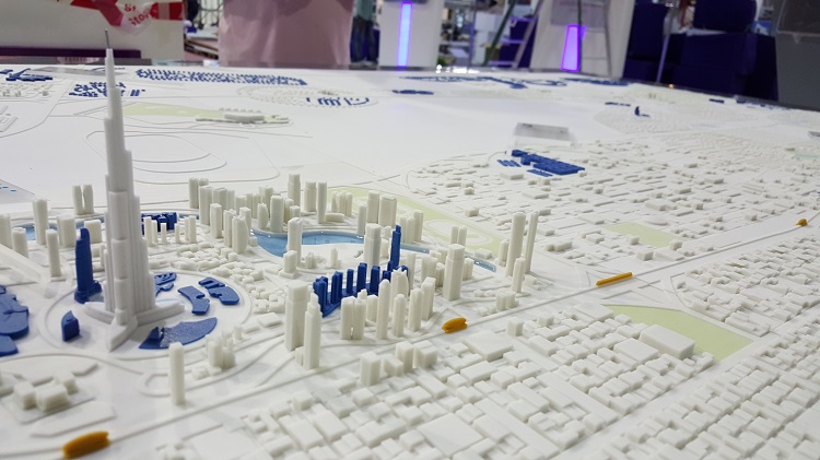 I recommend aligning the map, for example, in the upper left corner for a simpler placement of the shape for the cutout.
How to do it:
- Find and download the desired shape in .SVG format. Ideally, it should be on a white or transparent background. To make searching easier, I recommend adding the keyword “silhouette“.
- In a web browser, open the Tinkercad tool and sign in (or create a free account).
- Create a new design by pressing the Create new design button.
- Create a block (use the “Box” tool on the right) and change the dimensions so it stretches across the entire Workplane.
- Import the downloaded .SVG file with the shape using the Import button in the top right corner. When the import is complete, the image is automatically converted to a 3D object. Change the shape type to “Hole“.
- Click the object with the right mouse button and first adjust its height in the Z-axis so that it is higher than the block.
 Then, adjust the size of the model by dragging any corner to fit the block. To keep the aspect ratio hold the Shift key.
 - Now select both objects (Ctrl + A), group them with the Group button (Ctrl + G) and change to the “Hole” type. This creates a negative shape, which then cuts the terrain.
- Import the terrain model using the Import button in the top right corner and wait for it to finish.
- Adjust the size of the terrain model and place it in the right place in relation to the carved shape.
- Deselect the selection of objects by pressing the mouse outside the print area.
- Export the object using the Export button in the top right corner of the .STL format.
- The model is ready to be sliced, for example, in Slic3r, where it can be scaled in the Z-axis if needed for better terrain visualization.
Download link: The Czech Republic 3D terrain model on PrusaPrinters
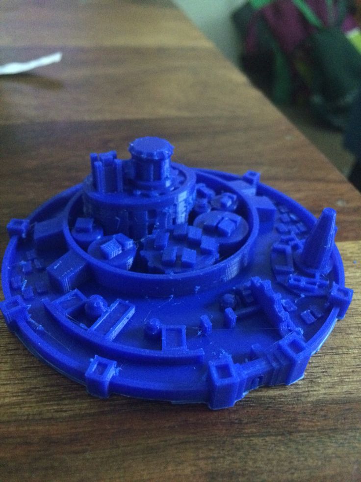
City model with terrainIn this case, the procedure is a little more complex than the terrain itself and more tools need to be used. To get the model, we use the CADMAPPER web tool, which uses freely available maps from OpenStreetMap as a source. The tool allows you to download a 3D model up to 1 km² area for free. Larger areas are paid. In most cases, 1 km² is perfectly fine. By covering the entire print area (25 x 21 cm), we get the ideal scale for the model (approximately 1: 4000 to 1: 5000).
- Open CADMAPPER tool in the browser and click Create a map.
- Select the desired area up to 1 km² (or larger and buy the model).
- Select the output format for SketchUp 2015+.
- Include Topography and 3D Buildings in the output model and choose the height of buildings for which the height in the map is not defined.
- Press the Create button to start generating.
- Press the Download button to download a generated zip file that contains the .SKP file.
The downloaded file is not yet fully prepared for slicing. What we need to do is to create an object under the terrain. In addition, we can simply change the height of buildings in this tool, especially those that have a default value from CADMAPPER. We will use SketchUp Pro for editing, which is free to download in the trial version.
Eneroth Terrain Volume extension is useful when you want to create a solid object under the terrain easily. Download this extension as well.
Add extensions using the Window -> Extension Manager. Press the Install Extension button and select the downloaded file from the previous step.
Now we have everything ready and we can start editing the model.
- Run SketchUp, open the downloaded file from CADMAPPER (File -> Open).
- On the right side of the application window, expand the Layers section and remove all layers except buildings, topography and Layer0. Press the “Delete content” icon. The content of the deleted layers is not easily printable, that’s why we’re deleting them.
 However, you can play around with the content of deleted layers and see if something interesting comes out of it – we won’t be using them in our guide, though.
 - Click anywhere on the terrain to select it. In the top menu of the app select Extensions menu -> Eneroth Terrain Volume. This creates a solid object under the terrain.
- If you want to change the height of the base or buildings, you must explode the model (select the whole model, right mouse button, Explode option), and then the Push / Pull tool to increase or decrease the height of the buildings or the base under the model.
- Export the model using File -> Export -> 3D Model.
The file is now ready for 3D printing. Open it in the Slic3r PE and adjust the size to fit the print area. For an area of 1 km², the approximately square shape of the model is reduced to about 20% of the original size. So we get the model on a scale of cca 1: 5000. We recommend a PLA material and a layer height 0.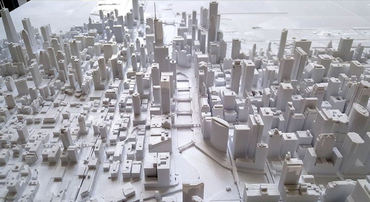 15mm.
15mm.
1:5000
1:2500
1:1000
Download link: Prague Castle area on PrusaPrinters
Preparing the model for printing and correct orientationUse Slic3r PE or your favorite slicer tool to generate the gcode file.
Terrain models with at least one straight edge can be printed in two ways, either horizontally or vertically. Each of these orientations has its pros and cons and for each model, it is necessary to decide which orientation to choose. Let’s look at the main differences.
The horizontal positionThis position is natural in the real world. In this position, we are able to print almost any model. In the Z-axis, however, we are limited by the height of the layer. The lowest height of the extruded material is about 0.05mm and the most commonly used nozzle diameter is 0.4mm. The relatively large diameter of the nozzle alone causes “drops” on the peaks. The nozzle diameter also affects edge sharpness.
We recommend selecting a layer height of 0.15mm and a 15% to 20% infill.
Pros:
- you can print almost any model
- there are horizontal lines on the model that represent contour lines (some may consider this a con)
Cons:
- infill is necessary (longer printing time)
- drops on peaks
- there may be strings between the peaks/buildings
In the vertical position, the biggest advantage is that no “drops” of material on the peaks will be created, and the peaks will be smoother. This makes the surface more detailed and looks much better. The vertical orientation is suitable for models where there are no areas that make an angle with the print area less than about 45°. Supports for such models is not a solution we would recommend.
Vertical orientation is also not suitable for printing city-building models, because almost every building would have a perimeter wall parallel to the print surface and therefore the model would be non-printable without supports.
With vertical orientation, it is advisable to choose the most suitable area on which the model will be placed. Choose the one that will touch the bed with the largest possible area. Use the Place on the face button to rotate the model.
We recommend selecting a layer height of 0.15mm and a 0% infill. Infill is not needed in most cases. The printing time will be almost half and you save some material. For best results, use PLA filament.
Pros:
- print without support and infill
- there is no stringing between peaks
- the terrain looks smoother than the horizontal print position
Cons:
- can not be used to print city models
- there’s a chance that it will become loose and that the print will fail
The difference of print in horizontal and vertical orientation is shown in the pictures below.
Our tips for color models:
- Use ColorPrint to change the color of the filament depending on the altitude.
 Learn how to use ColorPrint in this article.
 - Print the model with a single filament and paint it afterward. It depends only on your imagination.
- If you already have Original Prusa Multi Material Upgrade 2.0, you can try to create a color model to distinguish terrain, buildings, waterways and roads.
Feel free to experiment, try various changes and edits, and don’t forget to share the results in our forum.
3d City - Etsy.de
Etsy is no longer supporting older versions of your web browser in order to ensure that user data remains secure. Please update to the latest version.
Take full advantage of our site features by enabling JavaScript.
Find something memorable, join a community doing good.
( 1,000+ relevant results, with Ads Sellers looking to grow their business and reach more interested buyers can use Etsy’s advertising platform to promote their items.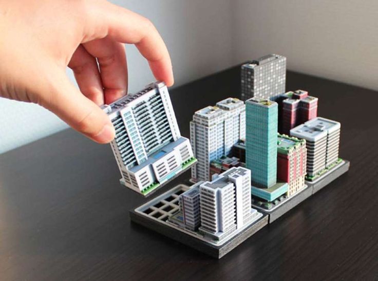 You’ll see ad results based on factors like relevancy, and the amount sellers pay per click. Learn more. )
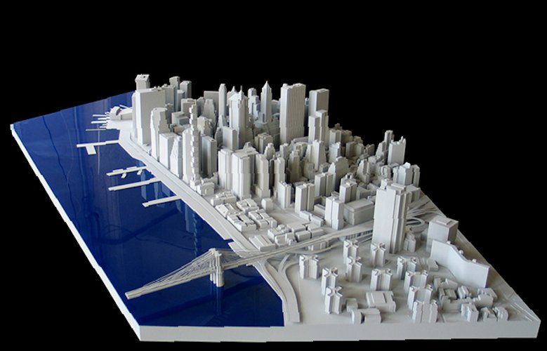
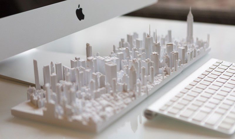
The largest 3D printed city model / Sudo Null IT News
I love cities, 3D models, layouts… A 3D printed city? Perfect! In 2014, the largest printed interactive 3D model of the city was presented in San Francisco, and a year and a half later, this status is still with her.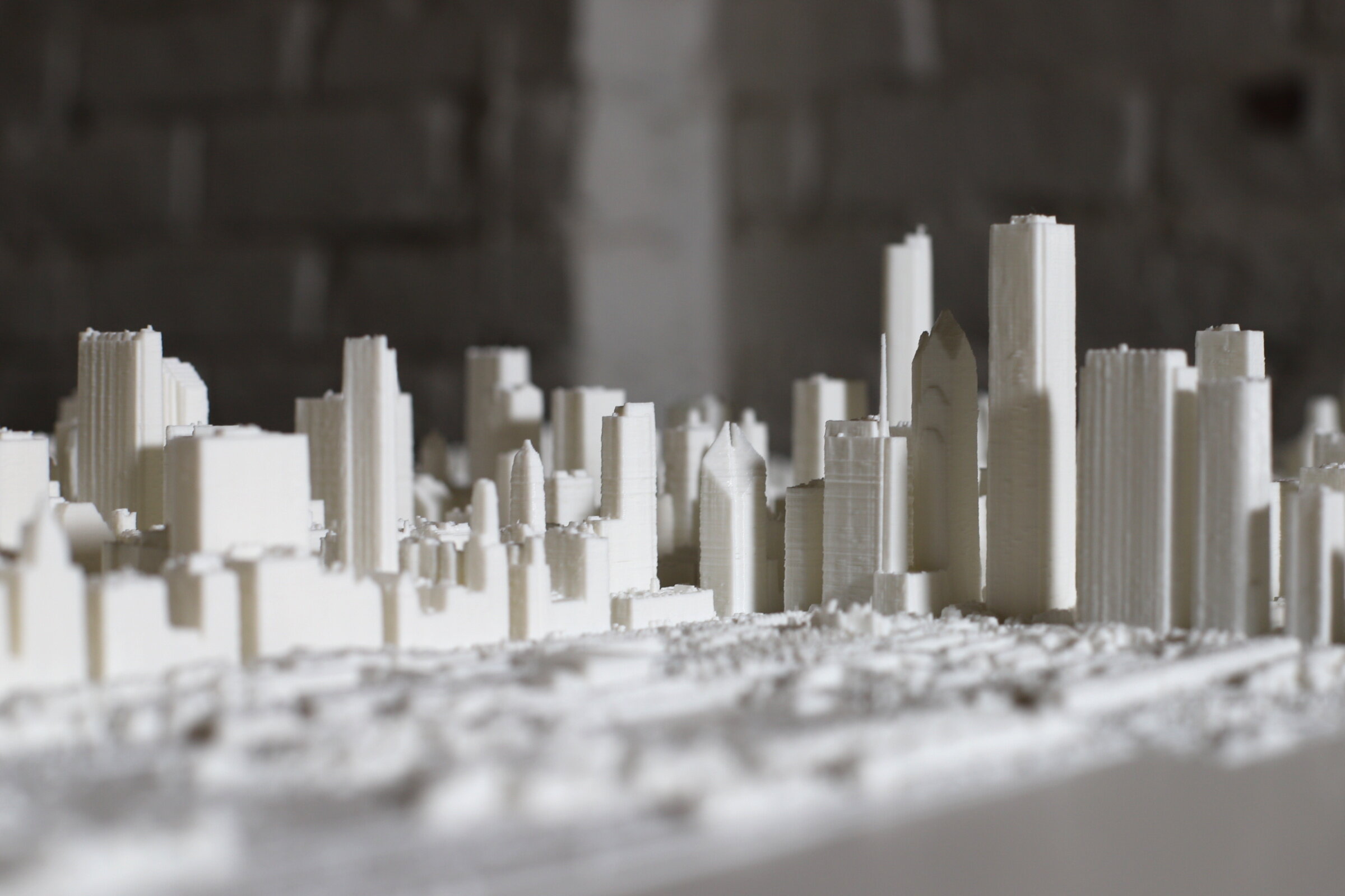 The layout still doesn't cover the whole city, but 115 blocks of northeast San Francisco at 16 micron print resolution and the appropriate level of detail is a really impressive result. I'm surprised no one has posted about this here. I will correct the injustice.
The model was developed by Steelblue, a creative agency engaged in the marketing of large construction projects, under the auspices of Autodesk, commissioned by a large real estate developer, Tishman Speyer. It was made in Autodesk's "creative workshops Pier 9" from VeroWhite photopolymer on two Objet500 Connex 3D printers with a print chamber of 500x400x200 mm. This printer combines a large volume chamber and high print speed with very thin layers, allowing you to quickly and accurately create large parts or even multiple parts in different materials. But even with such equipment, printing took 2 months, 5 days a week, 18 hours a day. The total weight of 68 kg is no joke to you. But there is still a manual post-processing stage, about 45 minutes per quarter.
The 3D model was created from a large amount of heterogeneous data. Topographic maps, and three-dimensional scanning, and photographs, and architectural projects from the archive were used. The covered area includes many local attractions that have been recreated with great care. Modeling took about 6 years: from 2008 to 2014. Even the 3D models of buildings available to the developer from previous projects could not be used: at a scale of 1:1250 and printer resolution, it turned out to be easier to build new ones than to simplify the old ones. The minimum detail size corresponds to approximately 30 cm in the real world.
Video of the construction process
The purpose of this large-scale project is to help the developer in urban planning. Any block can be replaced and see what happens. One of the advantages of 3D printing is the ability to easily maintain the relevance of the model. Another advantage is the higher detail, speed of production and low cost than the traditional hand-made layout. The main point of creating a layout in general is that it allows you to feel the space in a way that an arbitrarily realistic picture on the screen will not help. Although the virtual part of the model also plays an important role: the work is going on in it, and the layout itself is used for presentations.
In addition to the city model itself (in the state of 2017, when some large objects will be completed), the kit includes a projector located under the ceiling, which creates an interactive component for every taste. You can overlay future metro lines or roads on the layout (even simulate the flow of vehicles on them), you can sign the streets or display zoning on some basis. You can simulate the movement of the sun across the sky and follow the shadow zones. Only the limits of imagination limit the ways in which the backlight can be used.
Projector demo
The original with all associated hardware and software remains with the customer, Tishman Speyer.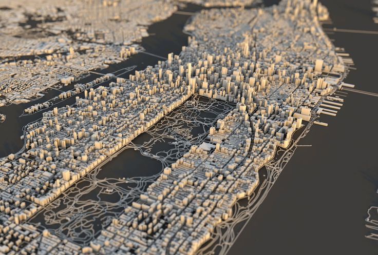 In the copy, which will be shown to the public in the Autodesk gallery, the backlight is planned to be built into the table itself from below, for beauty. Steelblue is ready to expand the model with new quarters, develop a more functional lighting option with several projectors, and would also like to print other cities, but with such a laborious work and a cost of several hundred thousand dollars, the San Francisco layout is still unique in terms of coverage of the territory .
Sources:
Presentation of the layout on the Autodesk website, there is also a report on printing in the Pier 9 workshop
A story by Jeff Mottle, owner of the architectural magazine CGarchitect, about Steelblue's work on this object and future plans
Own The site of the main modeler of this project, Jacob Gubler, also contains similar but smaller prints of Boston and Manhattan, as well as a print of San Francisco made of transparent material Veroclear.
eState - Print your city? 3D printing is revolutionizing our urban future
The Fabrication City concept puts manufacturing back into the hands of communities with 3D printers.
 This can have far-reaching implications for economic development, environmental sustainability, inclusion and other benefits. The use of 3D printing presents a huge opportunity for urban innovators and entrepreneurs.
 The 3D printing process can be used to create three-dimensional objects from layers of different materials using digital equipment. If local producers are given access to manufacturing labs equipped with technology for training, such an incubation environment could help future entrepreneurs.
The maker city model appeared around 2011, developed by the MIT Bits and Atoms Center, and is supported by over 1,000 Maker Centers that provide local manufacturers with access to 3D printing and other manufacturing tools. There are also neighborhoods and city clusters that facilitate initiatives in this direction.
Opportunities exist for individuals and groups to create and market products from new materials using digital devices and additive manufacturing.
By facilitating these activities, cities can radically change the way they produce and consume in their region. The interaction of people and processes creates local and regional inclusive innovation and economic growth while reducing environmental impact. What could we reuse if we innovate more inclusively, and how can we change the local economy if we support local resources?
Seal of the future
In the book Innovative Solutions for Sustainable Cities , in the section City Manufacturing , it is explained that in the future we should change the principles in our economy, focusing on sustainability, not profit maximization.
A comprehensive rethinking of urbanism will be required, a change in how we produce, consume and live in cities, the ability of cities to "digest" the waste they produce. Just as the digital economy offers platforms available to anyone around the world to make sales, new technologies like additive manufacturing are redefining where and how we make things.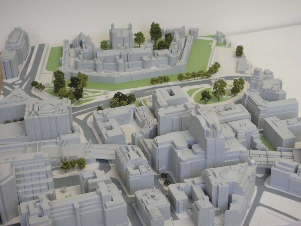
The use of 3D printing is already transforming many traditional industries. For example, GE can replace a third of the parts on an aircraft engine using 3D printing, and by combining materials they can reduce the total number of parts. Honda created an electric car exclusively from 3D printed segments. 3D printing machines may not be far off. These days, even homes are being 3D printed at a very reasonable cost - while still in its infancy, the results are only getting better from project to project.
Aircraft parts can now be printed on a metal 3D printer.
This manufacturing revolution will have significant implications, enabling cities and local businesses to mass-produce and produce just-in-time products. This will reduce transportation and waste and therefore help to minimize emissions. It can also lower the overall cost to consumers while increasing the number of on-site jobs.
Rethinking local production
Imagine cities equipped with flexible factories using local supply chains and locally sourced materials. These manufacturing sites use scrap, disassembled components and other sources to produce products on a "digital" device and customized to each individual. From prostheses to park benches made from waste plastic, all the way to refrigerators. Today, more and more products are being produced by 3D printing by entrepreneurs.
Industrial production has begun the transition from degenerate to regenerative design (these are processes that restore and renew sources of energy and materials), this concept is called Circular economy . For example, waste is recycled to meet new needs such as energy production.
The fabrication of the city is in line with social, economic, resource stewardship and sustainable development goals. This is a huge incentive for cities to engage in the creation of new urban systems that, by design, are constantly rebuilding. The Amazing City Global Initiative, launched in 2016, includes 27 municipalities and governments, including Detroit, Amsterdam, Bhutan, Shenzhen, Ekurhuleni, Santiago de Chile, Boston, and Paris.
There is an extensive network of designers, manufacturers and innovators from a wide range of economic sectors driving the development of consumer goods, energy, food, health and more. It is not hard to imagine that bulky products such as cars or refrigerators, which are expensive to transport and store, could in the future be made on demand on site.
Barcelona is perhaps the most easily recognizable work environment. Already a significant amount of food, materials and products are no longer produced thousands of miles away – they are conceived, designed and grown within urban boundaries.
City fabrication can be differentiated through design when a unique ecosystem is created that attracts innovative people and organizations, allowing cities to diversify and offer an unparalleled quality of life.