3D printing assemblies
How To 3D Print Assemblies With Moving Parts
By Laura Russart, Jul 20th, 2021
As 3D printing becomes increasingly present in the everyday vocabulary of engineers and designers, a new set of necessary skills emerges as well. With so many questions that need answering, the Fathom team is dedicated to sharing interesting information with you as we navigate the frontier of additive manufacturing. One of the many ways that 3D printing shines is in its ability to produce assemblies with moving parts, all in a single build. To investigate this, Mechanical Engineer Alexei Samimi took on the challenge of designing a single assembly of interlocking moving parts for two different 3D printers.
InspirationUsing 3D printing in the design process has many benefits. For this blog post, I wanted to do a quick project demonstrating how 3D printing allows you to quickly prototype complex and intricate assembled parts by printing multiple components pre-assembled in a single build.
I modeled a bracelet in Solidworks—a six-part 3D printed assembly with paraboloid joints and a fold-over clasp sliding mechanism. I printed the assembly on both a uPrint SE Plus (Fused Deposition Modeling Technology) and an Objet500 Connex3 (PolyJet Technology) and compared the results.
Design ConsiderationsClasp DesignTo explore how the two machines handle 3D printing intricate assemblies of moving parts, I looked to an everyday mechanism that would be time-consuming and difficult to prototype using traditional methods: the fold-over watch clasp [Figure 1].
A pair of 0.05-inch hemispherical snaps holds the clasp closed. The snap depends on flexure of small snap arms to operate and I was curious how well the uPrint’s ASBplus would compare to the Connex3’s Digital ABS. Both exhibit flexural moduli of 300 ksi.
Joint TypeFor this design, I wanted to avoid long through-pins like those found in metallic watch bands. Not only would the tiny 3D printed pins be prone to breakage and wear, but removing support material from the narrow pin holes would be difficult.
Instead, I employed paraboloid joint pairs: on either side of the band, a paraboloid pin, like the one shown in Figure 2, is mated to a shallow depression, slightly deeper than the pin. Not only would the short pin be more robust, but support material placed between it and the surrounding depression could be more easily removed.
Build OrientationThe orientation of the assembly on the build platform affects the surface finish, tolerances and the strength of walls and extrusions.
Consider the pins in each of the bracelet’s joints: On the uPrint (0.01-inch layer thickness in fine-resolution mode), a 0.07-inch long pin with a base diameter of 0.01-inches, its axis oriented perpendicular to the build platform (Fig. 3), will be composed of seven circular layers. This topography may be prone to shearing, but will turn smoothly in its socket. If the same pin axis is oriented parallel to the build platform (Fig. 4), it will have greater shear strength but lower radial smoothness.
Figure 2 – Wireframe view of a paraboloid joint in its socket.
Figure 3 (left) – Pin axis oriented perpendicular to build platform. Figure 4 (right) – Pin axis oriented perpendicular to build platform.
Comparatively, the Connex3 (16-micron layer thickness in fine-resolution mode) will produce a smooth pin in either orientation, allowing more emphasis to be put on surface finish and material efficiency.
Both models were oriented side-down to improve surface finish, maximize support material efficiency and improve radial smoothness of pins in the joints and clasp.
3D printed sliding and interlocking parts will be surrounded by support material and it’s important to consider how difficult and time consuming the support material will be to remove. Providing adequate clearance between parts, as well as minimizing the depth of small holes and channels, will aid in the removal of support material. I kept all mating clearances above 0.02-inches to ensure no fusing would occur between parts [Figure 5].
Figure 5- This image of two clasp components shows the minimum clearance in the model: 0.02-inches.
FDM / / / / / / / / / / / / / /
uPrint SE Plus FDM 3D printer… Nine color options available in ABSplus – an engineering-grade thermoplastic. Operates at either 0.010 inch or 0.013 inch layer thickness for finer resolution or higher speed, respectively.
PROS / / / / / / / / / / / / / /
Flexible, high-strength thermoplastic is great for snap-fits (flexural modulus: 300 ksi; tensile strength: 4,700 psi). Superior hardness (109.5 HR) is ideal for repeated clasp operation and wearability.
CONS / / / / / / / / / / / / / /
At 0.01-inches, layer topography is visible and if surface smoothness is a high priority, additional finishing may be necessary. A single pin between the band and the bracelet face became dislocated after rough handling. This was due to a combination of the high clearance creating too much play in the joint and the pins short length relative to the layer thickness. This error could be eliminated with slightly longer pins.
POLYJET / / / / / / / / / / / / / /
Objet500 Connex3 PolyJet 3D printer… Choose from hundreds digital materials, 14 base materials and up to 82 material properties in a single build.
PROS / / / / / / / / / / / / / /
High speed, high resolution and smooth matte finish. Joints function smoothly and without fail. The fold-over clasp has been operated many times and still snaps securely into place. Option to 3D print in multiple materials during a single build cycle—an ideal functionality for single-build assemblies.
CONS / / / / / / / / / / / / / /
While digital ABS matches ABSplus in terms of high tensile and flexure strength, its lower hardness (68 RHM) may be less suited to heavy use.
The uPrint created a bracelet I could try on and share with others. The joints moved smoothly and the fold-over clasp snapped in and out of place reliably. Support material was easily removed in an ultrasonic bath in less than 20 minutes. However, due to the machine’s lower resolutions, one of the joints failed due to a pin that printed too short. Aside from the joint failure, the uPrint produced a solid, durable model.
The Connex3 did an excellent job of creating a bracelet that looks and functions exactly as designed. Joints and clasp operated smoothly and the higher resolution of the Connex3 machine could allow for tighter clearances and thus tighter, smoother joints, where the assembly was designed specifically for it. However, the softer material showed light signs of wear after repeated use and I’m concerned that the fold-over clasp mechanism won’t last as long as the FDM version. Support material removal was more labor intensive, requiring careful cleaning in and around tight clearances.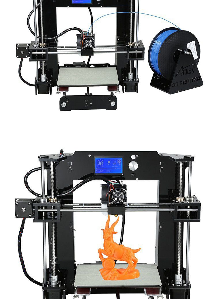
The ability to 3D print assemblies with moving interlocking parts is an exciting addition to the world of manufacturing and we at Fathom can’t wait to see how you explore these new possibilities! Share your creations with us on our Facebook page.
Have a bracelet of your very own to print? Upload your file to our online quoting and ordering system for 3D printing. SmartQuote offers PolyJet, FDM and SLS technologies — just click to print!
Facebook0
Twitter
LinkedIn0
Reddit
Tumblr
Pinterest0
0 Likes
How to Design an Assembly for 3D Printing
Time to read: 4 min
Engineers are always trying to make designs faster, better, cheaper, lighter. Before 3D printing, the only way to create prototypes was through subtractive manufacturing, where a block of material was cut away until only the part or a mold of the part remained. These components could only be produced and assembled one at a time. This prototyping method was slow and, in many cases, very expensive. Creating single part files one at a time using both through subtractive and additive manufacturing methods is still widely used.
However, producing moving assemblies with many articulating components working together has become faster and easier. Here are a few important tips when designing your assembly for 3D printing.
Leave Air Gaps
Always leave negative space or air gaps between components. When designing in 3D CAD, creating geometry in the same area as a separate component is both possible and easy. When the 3D printer receives a file with overlapping geometry, it will print the two or more parts together as if they were one component. That’s not ideal for a real-life, moving assembly with separate components that articulate against one another, so it’s important to check your models to make sure there is negative space between all parts in the assembly.
A good rule of thumb is that the air gaps should be at least double the layer thickness of your choice, which can be specified before the print. This allows the gap to be small enough to be unnoticeable at first glance but large enough to allow the soluble support material that fills the gap during the printing process to be washed away by the bath post-print. One additional note is that 3D printing is bilateral in tolerance (+/- X), whereas other machining operations can be set to unilateral tolerances (+ X, -Y).
As an example, I chose to model and print an adjustable wrench. I chose a layer thickness of 0.005”, which is the smallest possible option. To leave the appropriate amount of space between parts, I needed at least a 0.01” air gap (0.005” * 2) between all of my adjustable wrench’s component faces. This way, there is no risk at all that the extruded paths of the FDM printer will melt together while printing. One could argue that with all the different possible materials and printing types that are out there, the air gap could increase or decrease from this rule of thumb. While true, using the practice of doubling the air gap compared to the layer thickness of the 3D printed assembly will work as intended in most situations.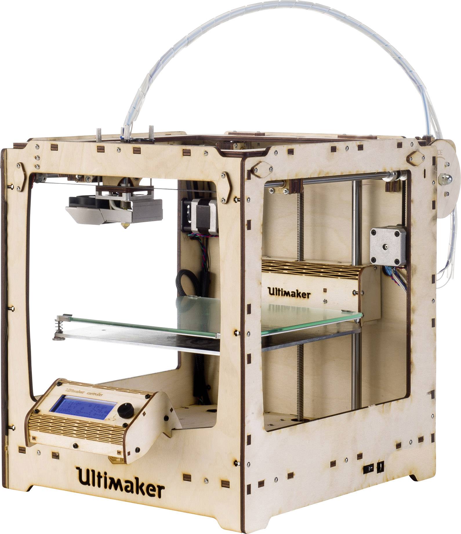
Soluble Support Material
For this method to work, using a 3D printer that extrudes not only model material but also compatible soluble support material is necessary. Using only model material will not work as model material will not dissolve in a bath. The support material is necessary because, during the printing process, the air gaps need to be filled with something substantial to keep the components of the print stationery and thus printable.
After the print has finished, it should be placed into a wash bath where the soluble support material can dissolve and wash away. Since the air gaps between components are small, the bath for a fully assembled 3D print can often take longer than for a single component 3D print because the bath can take longer to penetrate. Furthermore, the bath can only dissolve the little bit of material it is touching making the process take even longer. In the case of this 3D printed adjustable wrench, the support material took nine hours to wash away at 85º Celsius.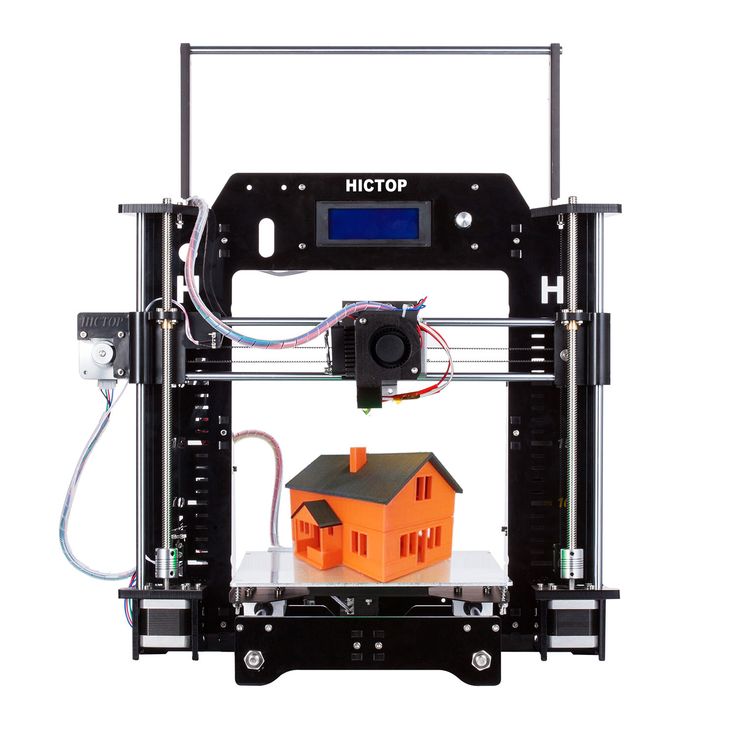
After the 3D print has been thoroughly washed and only model material is left, gently move the parts around to pry them further apart and generate the desired movement of the assembly. Be gentle at first; too much force, and the more delicate parts of the assembly may snap.
There is one important thing to keep in mind while designing assemblies. Even if you have adequate air gaps between all of the parts in the assembly, if the holes leading out to the water bath are too complicated, the soluble support deep in the model may never come in contact with the solution. The result? The support material in those gaps will not dissolve enough for the components to move, no matter how long the assembly remains in the bath. For this adjustable wrench example, I had to move the knurl and the replacement jaw a lot to finally loosen the remaining support material in the small gaps of the wrench that had not been washed away.
Reduce Friction
While not as vital as the first two points, reducing friction will help in the functionality of the 3D print. When an entire assembly is printed together and is not meant to come apart, the post-print modifications can be severely limited. If you can access all your 3D printed parts after printing, then you can sand and refine until you feel content, making sure everything fits and operates smoothly as you assemble. If, however, you have a component on the inside of an assembly (like a gear) and that has been printed with thick layer lines, it will not have a smooth finish and will produce more friction than compared to a component that has thin layer lines and a smoother finish.
Takeaways
While it’s possible to design and print an assembly with articulating surfaces all in one print job, there are times when it’s better to stick with printing individual components for subsequent assembly. For example, if your separate components are made of different materials and colors and you don’t have a printer that can print using various materials, you will be forced to print them one at a time and assemble them afterward. Other projects have complex features, like intricate channels or large hard-to-reach gaps, which makes the support material difficult to remove. In a case like that, it’s also likely better to print separately and assemble afterward.
Thank you for subscribing!
Building a home 3D printer with your own hands: recommendations from personal experience
3D printing and assembly of 3D printers is my hobby and passion. Here I will not share detailed diagrams and drawings, there are more than enough of them on specialized resources. The main goal of this material is to tell you where to start, where to dig and how to avoid mistakes in the process of assembling a home 3D printer. Perhaps one of the readers will be inspired by applied engineering achievements.
Why do you need a 3D printer? Use cases
I first came across the idea of 3D printing back in the 90s when I was watching the Star Trek series. I remember how impressed I was by the moment when the heroes of the cult series printed the things they needed during their journey right on board their starship.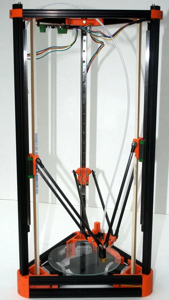 They printed anything: from shoes to tools. I thought it would be great someday to have such a thing too. Then it all seemed something incredible. Outside the window are the gloomy 90s, and the Nokia with a monochrome screen was the pinnacle of progress, accessible only to a select few.
Years passed, everything changed. Around 2010, the first working models of 3D printers began to appear on sale. Yesterday's fantasy has become a reality. However, the cost of such solutions, to put it mildly, discouraged. But the IT industry would not be itself without an inquisitive community, where there is an active exchange of knowledge and experience and who just let them dig into the brains and giblets of new hardware and software. So, drawings and diagrams of printers began to surface more and more often on the Web. Today, the most informative and voluminous resource on the topic of assembling 3D printers is RepRap - this is a huge knowledge base that contains detailed guides for creating a wide variety of models of these machines.
I assembled the first printer about five years ago. My personal motivation to build my own device is quite prosaic and based on several factors. Firstly, there was an opportunity to try to realize the old dream of having your own device, inspired by a fantasy series. The second factor is that sometimes it was necessary to repair some household items (for example, a baby stroller, car elements, household appliances and other small things), but the necessary parts could not be found. Well, the third aspect of the application is "near-working". On the printer, I make cases for various IoT devices that I assemble at home.
Agree, it is better to place your device based on Raspberry Pi or Arduino in an aesthetically pleasing "body", which is not a shame to put in an apartment or take to the office, than to organize components, for example, in a plastic bowl for food. And yes, you can print parts to build other printers :)
There are a lot of scenarios for using 3D printers. I think everyone can find something of their own.
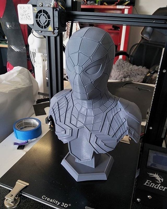
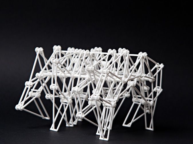
A complex part in terms of drawing that I printed on my printer. Yes, it's just a figurine, but it has many small elements
Ready solution vs custom assembly
When a technology has been tested, its value in the market decreases markedly. The same thing happened in the world of 3D printers. If earlier a ready-made solution cost simply sky-high money, then today acquiring such a machine is more humane for the wallet, but nevertheless not the most affordable for an enthusiast. There are a number of solutions already assembled and ready for home use on the market, their price range ranges from $500-700 (not the best options) to infinity (adequate solutions start from a price tag of about $1000). Yes, there are options for $150, but we, for understandable, I hope, reasons, will not dwell on them.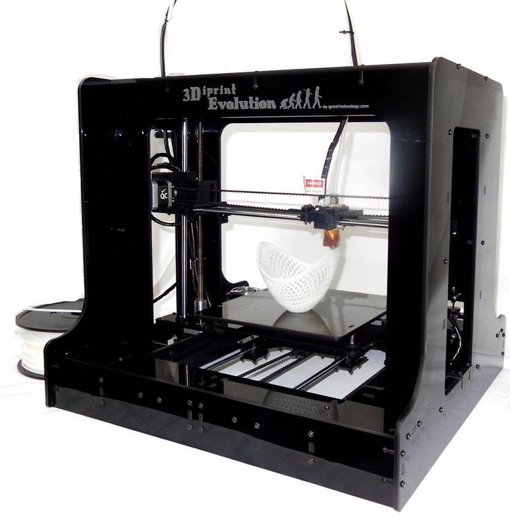
In short, there are three cases to consider a finished assembly:
- when you plan to print not much and rarely;
- when print accuracy is critical;
- you need to print molds for mass production of parts.
There are several obvious advantages to self-assembly. The first and most important is cost. Buying all the necessary components will cost you a maximum of a couple of hundred dollars. In return, you will receive a complete 3D printing solution with the quality of manufactured products acceptable for domestic needs. The second advantage is that by assembling the printer yourself, you will understand the principles of its design and operation. Believe me, this knowledge will be useful to you during the operation of even an expensive ready-made solution - any 3D printer needs to be serviced regularly, and it can be difficult to do this without understanding the basics.
The main disadvantage of assembly is the need for a large amount of time.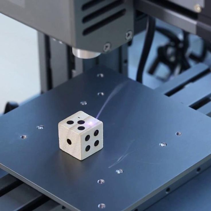 I spent about 150 hours on my first build.
What you need to assemble the printer yourself
The most important thing here is the presence of desire. As for any special skills, then, by and large, in order to assemble your first printer, the ability to solder or write code is not critical. Of course, understanding the basics of radio electronics and basic skills in the field of mechanics (that is, "straight hands") will greatly simplify the task and reduce the amount of time that needs to be spent on assembly.
Also, to start we need a mandatory set of parts:
- Extruder is the element that is directly responsible for printing, the print head. There are many options on the market, but for a budget build, I recommend the MK8. Of the minuses: it will not be possible to print with plastics that require high temperatures, there is noticeable overheating during intensive work, which can damage the element. If the budget allows, then you can look at MK10 - all the minuses are taken into account there.
- Processor board. The familiar Arduino Mega is well suited. I didn't notice any downsides to this solution, but you can spend a couple of dollars more and get something more powerful, with a reserve for the future.
- Control board. I'm using RAMPS 1.4 which works great with the Arduino Mega. A more expensive but more reliable board is Shield, which already combines a processor board and a control board. In modern realities, I recommend paying attention to it. In addition to it, you need to purchase at least 5 microstep stepper motor controllers, for example - A4988. And it's better to have a couple of these in stock for replacement.
- Heated table. This is the part where the printed element will be located. Heating is necessary due to the fact that most plastics will not adhere to a cold surface. For example, for printing with PLA plastic, the required surface temperature of the table is 60-80°C, for ABS - 110-130°C, and for polycarbonate it will be even higher
There are also two options for choosing a table - cheaper and more expensive. Cheaper options are essentially printed circuit boards with preheated wiring. To operate on this type of table, you will need to put borosilicate glass, which will scratch and crack during operation. Therefore, the best solution is an aluminum table.
 - Stepper motors. Most models, including the i2 and i3, use NEMA 17 size motors, two for the Z axis and one each for the X and Y axes. Finished extruders usually come with their own stepper motor. It is better to take powerful motors with a current in the motor winding of 1A or more, so that there is enough power to lift the extruder and print without skipping steps at high speed.
- Basic set of plastic fasteners.
- Belt and gears to drive it.
Examples of elements appearance: 1) MK8 extruder; 2) Arduino processor board; 3) RAMPS control board; 4) motor controllers; 5) aluminum heated table; 6) NEMA 17 stepper motor; 7) a set of plastic fasteners; 8) drive gears; 9) drive belt
This is a list of items to be purchased. Hardcore users can assemble some of them themselves, but for beginners, I strongly recommend purchasing ready-made solutions.
Yes, you will also need various small things (studs, bearings, nuts, bolts, washers ...) to assemble the case. In practice, it turned out that using a standard m8 stud leads to low printing accuracy on the Z axis. I would recommend immediately replacing it with a trapezoid of the same size.
M8 trapezoid stud for Z axis, which will save you a lot of time and nerves. Available for order on all major online platforms
You also need to purchase customized plastic parts for the X axis, such as these from the MendelMax retrofit kit.
Most parts available at your local hardware store. On RepRap you can find a complete list of necessary little things with all sizes and patterns. The kit you need will depend on the choice of platform (we'll talk about platforms later).
What's the price
Before delving into some aspects of the assembly, let's figure out how much such entertainment will cost for your wallet.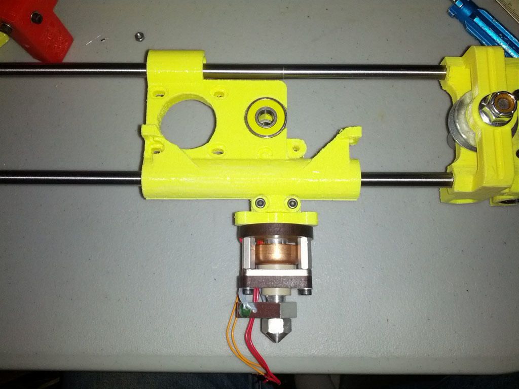 Below is a list of parts required for purchase with an average price.
Platform selection
The community has already developed a number of different platforms for assembling printers - the most optimal case designs and the location of the main elements, so you do not have to reinvent the wheel.
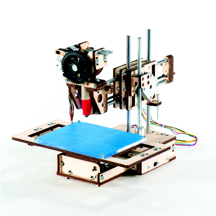
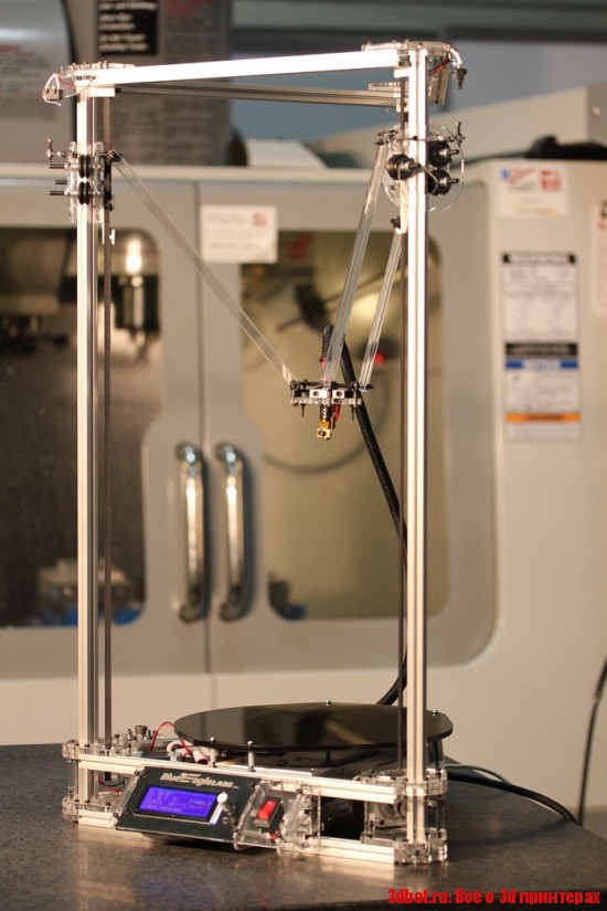
i2 and i3 are key platforms for self-assembly printer enclosures. There are also many modifications of them with various improvements, but for beginners, these two classic platforms should be considered, since they do not require special skills and fine-tuning.
Actually, illustration of platforms: 1) i2 platform; 2) i3 platform
On the plus side of i2: it has a more reliable and stable design, although it is a little more difficult to assemble; more opportunities for further customization.
The i3 variant requires more special plastic parts to be purchased separately and has a slow print speed. However, it is easier to assemble and maintain, and has a more aesthetically pleasing appearance.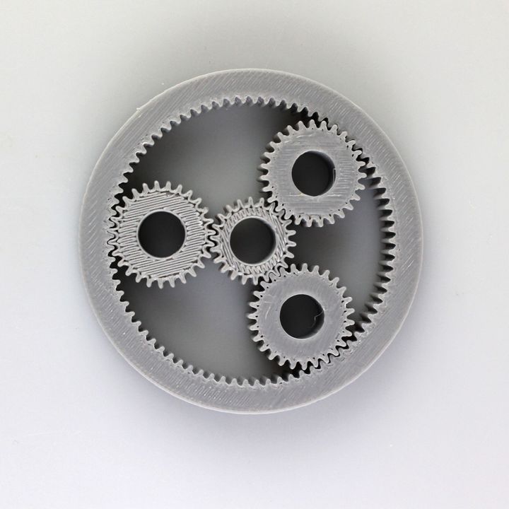 You will have to pay for simplicity with the quality of printed parts - the body has less stability than i2, which can affect print accuracy.
Personally, I started my experiments in assembling printers from the i2 platform. She will be discussed further.
Assembly steps, challenges and improvements
In this block, I will only touch on the key assembly steps using the i2 platform as an example. Full step by step instructions can be found here.
The general scheme of all the main components looks something like this. There is nothing particularly complicated here:
I also recommend adding a display to your design. Yes, you can easily do without this element when performing operations on a PC, but it will be much more convenient to work with the printer this way.
Understanding how all components will be connected, let's move on to the mechanical part, where we have two main elements - a frame and a coordinate machine.
Assembling the frame
Detailed frame assembly instructions are available on RepRap. Of the important nuances - you will need a set of plastic parts (I already talked about this above, but I'd better repeat it), which you can either purchase separately or ask your comrades who already have a 3D printer to print.
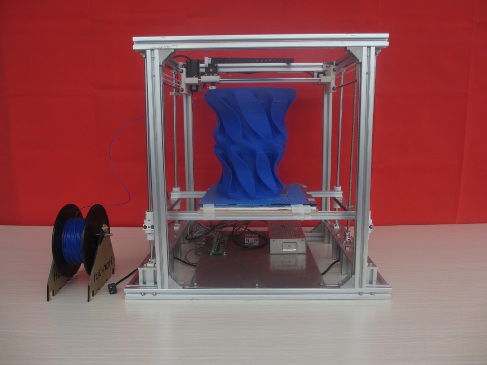
The frame of the i2 is quite stable thanks to its trapezoid shape.
This is how the frame looks like with parts already partially installed. For greater rigidity, I reinforced the structure with plywood sheets
Coordinate machine
An extruder is attached to this part. The stepper motors shown in the diagram above are responsible for its movement. After installation, calibration is required along all major axes.
Important - you will need to purchase (or make your own) a carriage for moving the extruder and a mount for the drive belt. Drive belt I recommend GT2.
The carriage printed by the printer from the previous picture after it has been assembled.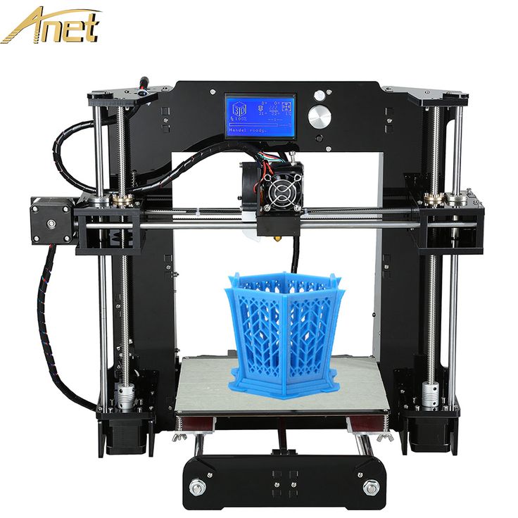 The part already has LM8UU bearings for guides and belt mount (top)
Calibration and adjustment
So, we completed the assembly process (as I said, it took me 150 hours) - the frame was assembled, the machine was installed. Now another important step is the calibration of this very machine and extruder. Here, too, there are small subtleties.
Setting up the machine
I recommend calibrating the machine with an electronic caliper. Do not be stingy with its purchase - you will save a lot of time and nerves in the process.
The screenshot below shows the correct constants for the Marlin firmware, which must be selected in order to set the correct number of steps per unit of measure. We calculate the coefficient, multiply it, substitute it into the firmware, and then upload it to the board.
Marlin 9 firmware constants0022
For high-quality calibration, I recommend relying on larger numbers in measurements - take not 1-1.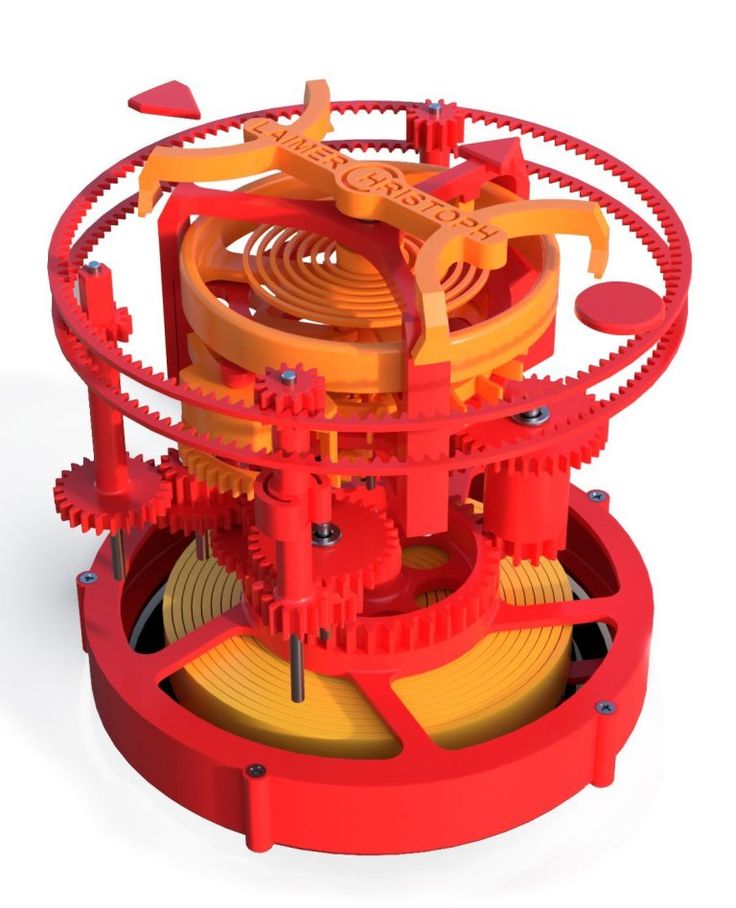 5 cm, but about 10. So the error will be more noticeable, and it will become easier to correct it.
Calibrating the extruder
When the frame is assembled, the machine is calibrated, we start setting up the extruder. Here, too, everything is not so simple. The main task of this operation is to correctly adjust the supply of plastic.
If underfeeding, the printed test item will have noticeable gaps, like test die 1. Conversely, the result will look bloated if plastic is overfed (dice 2)
Getting Started Printing
It remains for us to run some CAD or download ready-made .stl, which describe the structure of the printed material. Next, this structure needs to be converted into a set of commands understandable to our printer. For this I use the Slicer program. It also needs to be set up correctly - specify the temperature, the size of the extruder nozzle. After that, the data can be sent to the printer.
Slicer interface
As a raw material for printing, I recommend starting with regular ABS plastic - it is quite strong, products made from it are durable, and it does not require high temperatures to work with.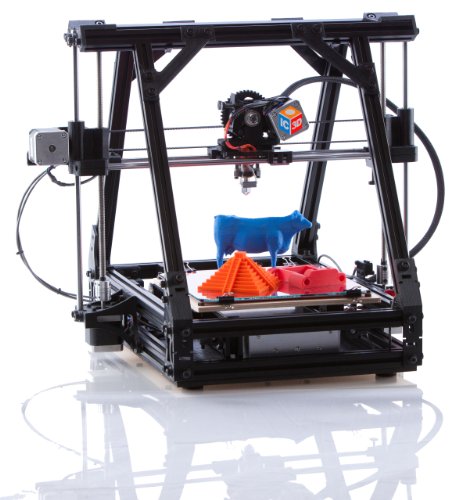 For comfortable printing with ABS plastic, the table must be heated to a temperature of 110-130 ° C, and the extruder nozzle - within 230-260 ° C.
Some important details. Before printing, calibrate the machine along the Z axis. The extruder nozzle should be approximately half a millimeter from the table and ride along it without distortion. For this calibration, a regular sheet of A4 paper inserted between the nozzle and the surface of the heated table is best suited. If the sheet can be moved with little effort, the calibration is correct.
Another thing to keep in mind is the surface treatment of the heated table. Usually, before printing, the surface of the table is covered with something that hot plastic sticks to well. For ABS plastic, this can be, for example, Kapton tape. The disadvantage of adhesive tape is the need to re-glue it after several printing cycles. In addition, you will have to literally tear off the adhering part from it. All this, believe me, takes a lot of time.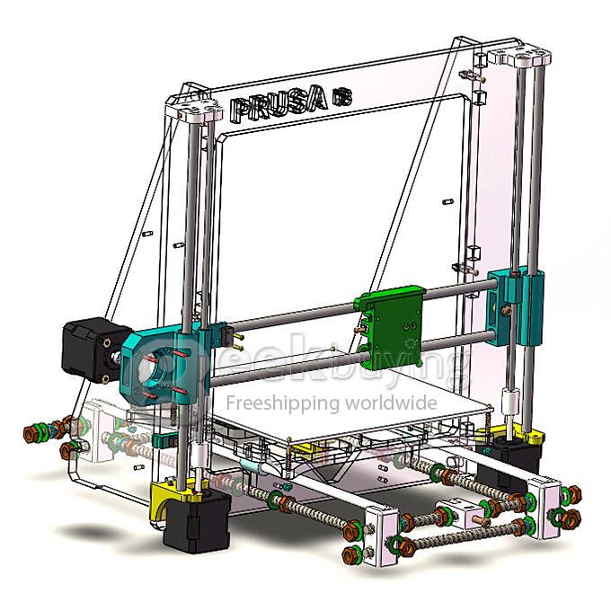 Therefore, if it is possible to avoid this fuss, it is better to avoid it.
An alternative option that I use instead of scotch tape is to apply several layers of ordinary light beer, followed by heating the table to 80-100 ° C until the surface is completely dry and re-applying 7-12 layers. It is necessary to apply the liquid with a cloth moistened with a drink. Among the advantages of this solution: ABS plastic separates from the table on its own when it cools down to about 50 ° C and is removed without effort, the table does not have to be peeled off, and one bottle of beer will last you for several months (if you use the drink only for technical purposes :)).
After we have collected and configured everything, we can start printing. If you have an LCD screen, then the file can be transferred for printing using a regular SD card.
The first results may have bumps and other artifacts - do not worry, this is a normal process of "grinding" the printer elements, which will end after a few print cycles.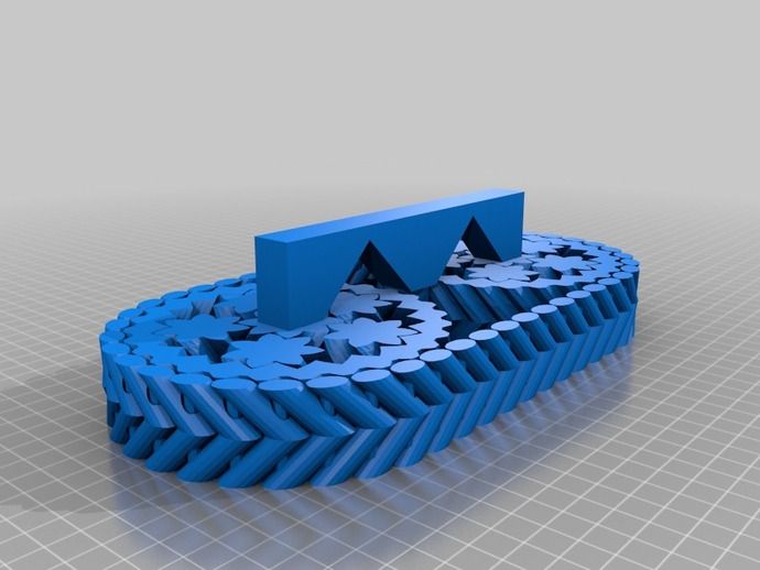
Tips to make life easier (and sometimes save money)
In addition to the small recommendations given in the text above, in this section I will also give a short list of tips that will greatly simplify the operation of a 3D printer and the life of its owner.
- Do not experiment with nozzles. If you plan to immediately print from materials that require high temperatures, then it is better to immediately take the MK10 extruder. On MK8, you can "hang" special nozzles that support high-temperature conditions. But such modifications often cause difficulties and require special experience. It is better to avoid this fuss on the shore by simply installing the right extruder for you.
- Add starter relay for heated table. Improving the power supply system for this important printing part with a starter relay will help solve the known problem of RAMP 1.4 - overheating of the transistors that control the power of the table, which can lead to failure of the board.
 I made this upgrade after having to throw away a few RAMPS 1.4s.
 - Select the correct filament diameter for printing. I recommend using 1.75mm plastic for MK8 and MK10. If we take plastic, for example, 3 mm, then the extruder simply does not have enough strength to push it at an acceptable speed - everything will be printed much longer, and the quality will drop. ABS plastic is ideal for MK8, MK10 will be able to produce products from polycarbonate.
- Use only new and precise X and Y guides. Print quality will be affected. It is difficult to count on good quality with bent or deformed guides along the axes.
- Take care of cooling. During my experiments with various extruders, the MK10 showed the best results - it prints quite accurately and quickly. The MK10 can also print plastics that require a higher print temperature than ABS, such as polycarbonate. Although it is not as prone to overheating as its younger brother MK8, I still recommend taking care of its cooling by adding a cooler to your design.
 It must be permanently enabled, this option can be configured in Slicer. You can also add coolers to keep the stepper motors at an acceptable temperature, however, make sure that their air flows do not fall on the printed part, as this can lead to its deformation due to too rapid cooling.
 - Consider heat retention. Yes, on the one hand, we are struggling with overheating of the elements. On the other hand, a uniform temperature around the printer will contribute to high-quality printing (the plastic will be more pliable). To achieve a uniform temperature, you can put our printer, for example, in a cardboard box. The main thing is to connect and configure the coolers before that, as described above.
- Consider insulating your desk. Heated table heats up to high temperatures. And if part of this heat leaves properly, heating the printed part, then the second part (from below) just goes down. To concentrate the heat from the table onto the part, you can perform an operation to insulate it.
 To do this, I simply attach a cork mouse pad to its bottom using stationery clips.
Pins
I am sure that during the assembly process you will encounter a number of difficulties specific to your project. Neither this text nor even the most detailed guides will insure against this.
As I wrote in the introductory part, the above does not claim the status of a detailed assembly manual. It is almost impossible to describe all the stages and their subtleties within the framework of one such text. First of all, this is an overview material that will help you prepare for the assembly process (both mentally and financially), understand whether you personally need to bother with self-assembly - or give up on everything and buy a ready-made solution.
For me, assembling printers has become an exciting hobby that helps me solve some issues in home and work affairs, take my mind off programming and do something interesting with my own hands. For my children - entertainment and the opportunity to get unusual and unique toys. By the way, if you have children whose age allows them to mess around with such things, such an activity can be a good help for entering the world of mechanics and technology.
For everyone, the vectors of using 3D printers will be very different and very individual. But, if you decide to devote your personal time to such a hobby, believe me, you will definitely find something to print :)
I will be glad to answer comments, remarks and questions.
What to read/see
- what can be printed;
- 3D printer forum;
- RepRap community site with model descriptions and assembly instructions;
- printer that prints electronics.
Subscribe to the Telegram channel "DOU #tech" so you don't miss new technical articles.
Topics: DIY, embedded, tech
Complete kit for assembling 3D printer Prusa i3 Hephestos
home » 3D printers » Assembly kit » Prusa i3 Hephestos
3D Printer Assembly Kit Description Reviews (0)
New product from bq is a custom version of the popular RepRap DIY kit - Prusa i3 Hephestos , which comes in a beautiful box with detailed assembly and setup instructions. This 3d printer is one of the cheapest available on the market.
Main advantages of Prusa i3:
- Printer assembly step by step
High quality parts and well-developed clear instructions will turn printer assembly into a game.
- Ease of use
Typing is comfortable, easy and safe
- Open source software and proprietary parts
The Prusa i3 Hephestos is 100% open source, allowing you to modify and evolve the printer at any time.
- Number of extruders: 1
- Nozzle diameter: 0.4 mm
- Print area: 210 x 215 x 180 mm
- Directional blowing of the extruder nozzle
- Print speed up to 40-100 mm/s
- Layer thickness 60-300 microns
- Made in Spain
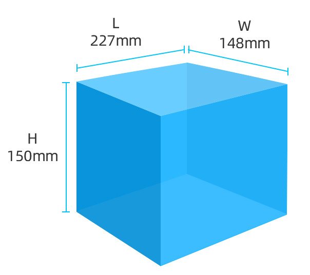
| Weights and dimensions | |
| Weight | 9.00kg |
| Dimensions (L x W x H) | 75. |