3D printers electronics
3D printing electronics: Transforming the electronic industry
3D Learning Hub
See all categories
Contents:
- Introduction
- What are the advantages of 3D printing for electronics?
- 3D printing with electrostatic discharging properties
- Conductive 3D printing offering new opportunities
- 3D printed electronics: What is possible?
- What about the future of 3D printing in the electronics industry?
Introduction
What are the advantages of 3D printing for electronics?
3D print the perfect prototype
3D printing helps you get from the idea to the product in a matter of days.Launch your first series
Moreover, the electronics industry can truly benefit from additive manufacturing. No stock, no minimum number of units and short turnaround are the key upsides of using Sculpteo’s 3D printing service for your electronic devices, regardless of where they are in product life cycle management. Electronic production is made easy thanks to our 3D printing technology and will improve and simplify your whole supply chain management! 3D printing and electronics are strongly linked. Online 3D printing allows you to create a new kind of relationship with your clients. You can easily produce small series, limited editions and spare parts in a small batch. Whether you’re looking for just a prototype or a thousand units, your 3D printing product will benefit from our experience and know-how to achieve the best quality.
 Design freedom
Electronic components production can now be thought in terms of 3D design and not only 2D, with new ways of stacking the circuits. It opens new possibilities to design for electronics, that are new to explore! Customization is becoming a big asset while using additive manufacturing for the creation of your products: you can create parts perfectly adapted to a circuit board or any electronic device. 3D printing can be used to create personalized electronic enclosures, USB stick cases, and keyboards, for example. Using additive manufacturing also offers you flexibility in the creation of your design. More than a perfectly adapted device, you can also elaborate complex geometries impossible to make with other traditional manufacturing techniques. With 3D printing, you can also make the most of parts that don’t require any assembly process!
 3D printing with electrostatic discharging properties
What is an electrostatic discharge?
What is called “electrostatic discharge” (ESD) is the flow of electricity between two electrically charged parts causes by contact. Static electricity often causes ESD through a process known as tribocharging. This static electricity can arise when surfaces rub together and this results in an excess of electrons on one surface and a deficiency on the other. The ESD occurs when differently-charged objects are brought close together or when the dielectric between them breaks down, often creating a visible spark. Electrostatic Discharges are a real problem and can damage sensitive electronic components. It can also lead to the alteration of magnetic media and set off fires, explosions in flammable environments! ESD is a big concern for the electronic industry, and being able to manufacture ESD-safe part is a real advantage to avoid any problem.
Focus on: Ultrasint PA 11 ESD
At Sculpteo, we are now offering you the possibility to manufacture your ESD-safe parts. If you are prototyping or producing a project where electrostatic discharging safety is critical, our Ultrasint® PA11 ESD material will be a perfect choice. Ultrasint® PA11 ESD is a bio-derived material, appearing to be a perfect choicel for increased process safety in advanced applications. With its interesting mechanical properties, this material offers new possibilities for a wide range of new applications, especially for the electronics sector. Indeed, with its low resistivity, Ultrasint® PA11 ESD is reducing the risk of electrostatically induced damage or failures, the material does not accumulate static electricity and can come in contact with electronic components without running any risk. The surface resistivity of Ultrasint® PA11 ESD is lower than traditional electrostatic dissipating materials. You can now make the most of the advantages of both additive manufacturing and electrostatic discharge properties. For electronic housing, electronic jigs and fixtures, this material is perfectly adapted. PA 11 ESD also as other advantages and interesting mechanical properties such as high tensile strength and elasticity, which could help you create efficient tools. What are you waiting for? With this material, you can create parts combining superior mechanical and thermal characteristics with outstanding electrostatic discharging properties. Get your parts 3D printed with Ultrasint® PA11 ESD by uploading your 3D file on our 3D printing service right now. It will only take a few clicks and you will get an instant quote.
Conductive 3D printing offering new opportunities
3D printing complex electronic components could go even further with conductive 3D printing. The creation of electronic devices with conductive features using 3D printing can particularly be useful to develop IoT (Internet of Things) projects. This innovative technology could allow creating 3D printed devices like LED, or touch sensors. But this ability to 3D print conductive devices could be involved in bigger projects, in soft robotics, 3D electronics, and also for communication devices such as 3D printed Near Field Communication (NFC) antennas.
3D printed electronics: What is possible?
As you will see, this 3D technology can be used for various applications in the electronics industry. Get inspired by these innovative electronic devices made using additive manufacturing!
3D printed circuit board by Nano Dimension and Harris Corp: 3D Printed Circuit Boards
Nano Dimension is known to work actively on 3D printed electronic devices The Nano Dimension’s DragonFly™ system is used to 3D print functional electronics prototypes and complex multi-layer Printed Circuit Boards (PCBs). But that is not all.
Nano Dimension and Harris Corp partnered to develop 3D printed electronic devices to create a radio frequency (RF) amplifier. They now work to go further and create hardware for the International Space Station. Their goal is to optimize the 3D printing process for RF components for flight studies aboard the ISS. Using additive manufacturing is a solution for them to find new ways to create radio frequency and circuit boards to find new innovative techniques.
The Simusolar project
At Sculpteo, some of our customers are working on solar energy using 3D printing. On the blog, we already told you about Simusolar, a company created in 2014 and looking to bring solar energy to the rural population of Tanzania. They develop and implement small-scale sustainable solutions to help local people in their everyday life.
They decided to use 3D printing because they needed a lot of custom made parts, for a low price. Their clients are farmers, fishers, or rural residents looking for various equipment powered by solar energy.
Optomec developing the Aerosol Jet Technology
Optomec announced that their Aerosol Jet Technology will be printing embedded electronics at the micron scale. The innovative process relies on both local deposition and local curing. This way, electronics parts are more affordable and require less waste of materials, and all of this with a superior resolution.
Start 3D printing enclosures!
3D printing enclosures are one of the most common uses of 3D printing for the electronic industry. Solidity, quality, customization, and accuracy, this is what you will make the most of while 3D printing your electronics enclosures.
If you are interested in 3D printing your own enclosure, you can follow our 3D printed enclosure design guide!
What about the future of 3D printing in the electronics industry?
What if in a few years, we could be able to create fully-functional smartphones or multi-material products using additive manufacturing? If these ideas are still dreams today, the innovations related to conductive 3D printing and electronic devices are now showing new opportunities. It might be time to rethink the way we conceive enclosures, circuit boards, and electronic components. From your prototyping process to the production and the management of your supply-chain, additive manufacturing could help you go through new challenges.
As you can see additive manufacturing has a lot to offer for electronics. It could become quite common to 3D print electrical elements. If you have an electronic project, but you don’t know what software you could use to start it: here is our selection of the best CAD software for electronics. Then, don’t hesitate to try out our online 3D printing service. You will just have to upload your 3D file, we will take care of it and send you your 3D printed objects in a few days.
Related Topics
- Return to Top
Get the latest 3D printing news delivered right to your inbox
Subscribe to our weekly newsletter to hear about the latest 3D printing technologies, applications, materials, and software.
What are 3D Printed Electronics? Let us tell you.
 ..
..Design
The complexity of electronics combined with the capabilities of 3D printing. Heard of 3D printed electronics but want to know more?The ability to 3D print electronics is making waves in an industry plagued by long stints of R&D and a never ending cycle of prototypes and new releases.
But what exactly does this process entail? And how, as a designer, architect, or artist, can it help you? Is it sustainable? What are the dangers? And what should you know about it?
This guide is a useful starting point for you to find out…
With 3D printing electronics it is possible to make various types of boards that can be programmed and connected to prototypes – ©iakovenko123/Depositphotos. com – Cover image – ©iprescott10/Depositphotos.comWhat is it?
3D Printing objects with electronic functionality is a relatively new concept.
It involves the use of material jetting technology, which is used to jet conductive and insulating inks onto the printing surface.
These inks are applied in lines as thin as a few microns before UV light is used to solidify the inks.
The use of material jetting facilitates multi-material 3D printing, which is particularly useful for the electronics industry.
This means that the different elements necessary in electronics, such as functional circuitry and enclosures, can be manufactured in a single print run.
3D printing electronics involves the use of material jetting technology, which is used to jet conductive and insulating inks onto the printing surface – ©IgorVetushko/Depositphotos.comWhat materials are used when 3D printing electronics?Where systems could typically use just one material in the 3D printing process, recent advancements have enabled the involvement of multiple materials.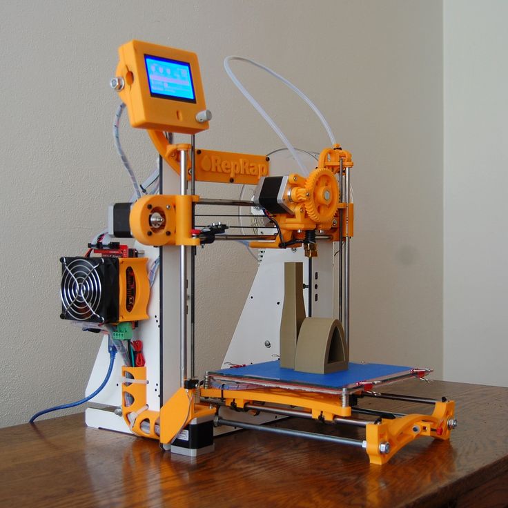
This allows manufacturers to merge conductive materials with non-conductive materials.
The thermoplastics used in the 3D printing process are often made with copper, carbon and graphene.
Meanwhile, proprietary conductive and dielectric inks are used simultaneously to build functional circuits and antennas. This expands the range of functions in 3D printed electronics.
Because the process combines multiple materials into the same 3D object it also requires a solvent to ensure their compatibility. The particular solvent used is known as an orthogonal solvent, which is specifically designed not to cause damage to the different components.
The thermoplastics used in the 3D printing process are often made with copper, carbon and graphene – © Julian Pagliaccio, via Wikimedia CommonsWhat can 3D printing electronics produce?With 3D printing electronics, it is possible to make various types of boards that can be programmed and connected to prototypes.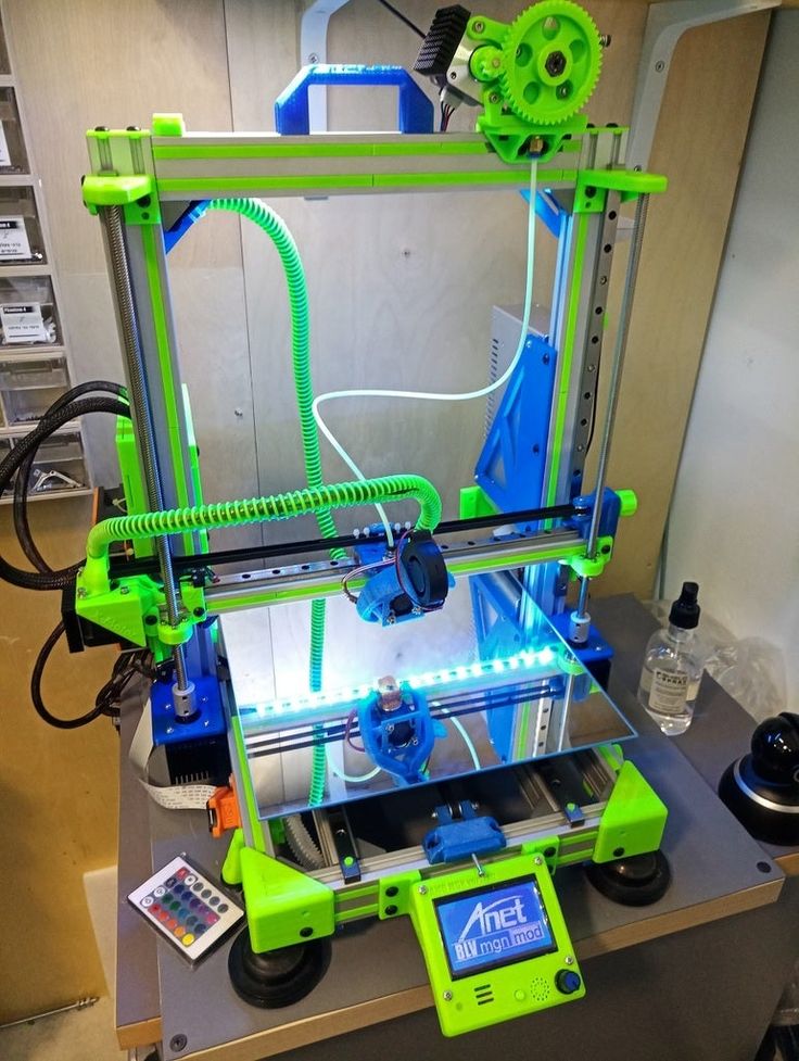
A very wide range of inks can be utilized enabling a full range of printed electronics functionality: conductors, semiconductors, dielectrics, resistors and more.
The process can be used to manufacture electronic components such as resistors, capacitors, antennas, sensors, and thin film transistors.
Using the 3D printing process, it is also possible to rapidly 3D print fully functional electronic circuits that contain electrically-conductive metallic inks and insulating polymeric inks, which could be useful for medical devices, radio frequency shielding surfaces and novel structures for harvesting solar energy.
Today, however, it’s main applications include printing electronics for use in prototypes for upcoming products, prosthetics and more complexly shaped electronic products.
Give me a step-by-stepWhile several methods exist for 3D printing electronic components, they typically mirror the various steps utilised in regular 3D printing.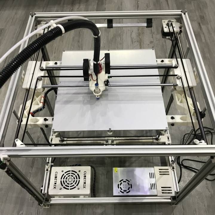 The main difference is the use of a dual-material fused filament process with conductive thermoplastic filaments.
As with all 3D printing, a digital CAD model of the desired part is designed, which serves as the printer’s instruction model.
When the printing process begins, a trace or “fingerprint” is created, and then the requisite materials needed for that specific part are added in layers.
The process flow of the 3D systemWhat machinery is used when 3D printing electronics?Specialised machinery is required which integrates a precise inkjet deposition printer with dedicated nano-inks and software capable of printing electronic circuits such as printed circuit boards (PCBs), antennas, capacitors and sensors.
Can I do it at home?Due to the complexity of the process, it is not possible to replicate it at home unless you have the capability of manufacturing your own 3D printer.
With the relevant machinery, it is possible to 3D print electronics at home.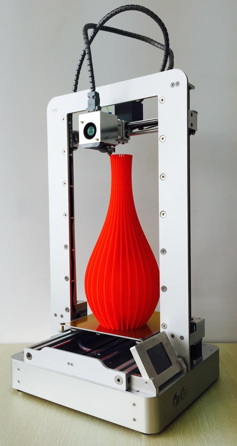
Find out more about manufacturing processes, don’t miss What is Explosive Forming? Let us tell you…
The benefits of 3D printing electronics range from faster time-to-market, greater freedom of design and customizationWhat are the pros & cons of 3D printed electronics?At the core of every electronic device is a Printed Circuit Board (PCB) which is difficult to produce. Luckily, with the advent of 3D printing, manufacturing these circuit boards is less challenging.
The benefits of 3D printing electronics range from faster time-to-market, greater freedom of design and customisation.
This is because with the advent of 3D printing electronics manufacturers can create prototypes of circuits and circuit birds in-house, reducing procurement expenses and eliminating concerns about IP infringement.
3D printing also opens up opportunities to design complex shapes and components. For example, multilayer circuits can now be 3D printed on non-flat, flexible surfaces, which would not be possible with traditional manufacturing techniques.
Components can also be printed onto 3D surfaces eliminating the need for a separate substrate and reducing the size, thickness and weight of the end product.
However, there are several limitations when it comes to 3D printing electronics, not only because it is limited in the types of parts it can produce.
Whilst the recyclability of 3D printed electronics is an area being explored by various researchers, it remains a con due to what is currently possible.
Another downside to 3D printed electronics, and in fact, all 3D printed products is their structural integrity.
Whilst printed layers adhere together in some cases, and under certain stresses or conditions, they can delaminate.
Another major downside to 3D printing as a whole is its increasing popularity and accessibility. On one hand, it democratises the manufacturing processes but it also makes it easier to fake and counterfeit products.
I want to know if it’s sustainable…Whilst 3D printing electronics can minimise the manufacturing footprint by localising production, the difficulty in recycling the various components means it can’t be considered a sustainable process.
There are several resources that are useful when it comes to building your knowledge around 3D printed electronics.
If you want to learn more check these out:
- A visual demonstration of the 3D printing process used to manufacture electronics.
- An explanation of the various capabilities of 3D printing electronics.
- A paper detailing the evolution of 3D printing electronics.
- A breakdown of the various benefits and current systems employed when 3D printing electronics
- A detailed research into the future of 3D printing electronics and its benefits when used for prototyping.
Fascinated by 3d printing? Don’t miss 3D printing ceramics: Interview with Hilda Nilsson.
3D printers in the electronics industry
3D printers in the electronics industry3D hardware supplier since 2010
+7 495 646-15-338 800 333-12-82
3D scanners3D printers About the companyServices
and ProjectsDemo HallGovernment ProcurementDeliveryService3D Encyclopedia
BlogContacts
Manufacturers of consumer electronics and commercial devices are actively using the possibilities of 3D printing to optimize development time and cost.
- What to print
- Advantages 3D
- Case: Microphone for U2
- Select 3D printer
- Printers use common types of plastics (such as ABS) commonly used in instrumentation. Polymer resins are also used to print high-precision prototypes and test samples.
What products are 3D printed by electronics manufacturers:
- concept models for visual evaluation or market research;
- test prototypes to test functionality, ergonomics, assembly of complex structures;
- ready-to-use articles or individual items;
- silicone casting master patterns.
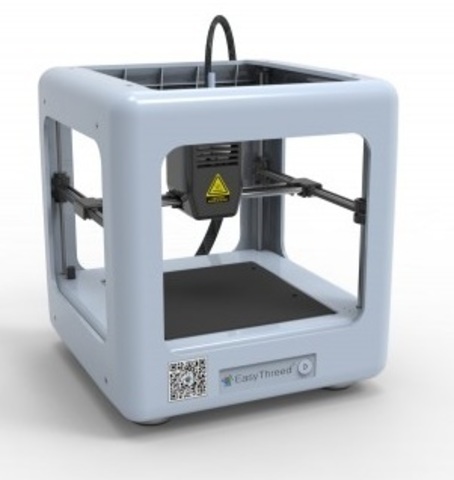
Many 3D printers use common types of plastics (such as ABS) commonly used in instrumentation. Polymer resins are also used to print high-precision prototypes and test samples.
Which products are 3D printed by electronics manufacturers:
- concept models for visual evaluation or market research;
- test prototypes to test functionality, ergonomics, assembly of complex structures;
- ready-to-use articles or individual items;
- silicone casting master patterns.
Why use 3D printers in production
- Reduced lead times. It takes only a few hours to create a prototype of a new device using a 3D printer. You no longer have to wait 2-3 weeks for a contractor to make a sample for you.
- Reducing the cost of production. The cost of manufacturing an object on a 3D printer is several times lower than if you create a mold for this.

- Preservation of trade secrets. 3D printer in the office will allow you to save all the details of new developments within the company. You do not need to share information with third-party customers to produce the desired part.
- Extensive testing and development options. You can make as many prototypes as you need quickly and cheaply. Test, make improvements - until you reach the ideal.
Examples of using 3D printing in electronics manufacturing
How Logitech uses 3D printing
A major personal electronics manufacturer uses various types of 3D printers during the design and testing of new products.
For example, Logitech creates prototypes of computer mice from a translucent photopolymer in order not only to evaluate the ergonomics and appearance of a new product, but also to analyze the location of components inside the design.
3D printing was also used to assemble test samples of one of the company's headsets.
 Comprehensive testing allowed us to release the most convenient, durable and functional product in a very short time.
 Why use 3D printers in production
- Reduction of terms. It takes only a few hours to create a prototype of a new device using a 3D printer. You no longer have to wait 2-3 weeks for a contractor to make a sample for you.
- Reducing the cost of production. The cost of manufacturing an object on a 3D printer is several times lower than if you create a mold for this.
- Preservation of trade secrets. 3D printer in the office will allow you to save all the details of new developments within the company. You do not need to share information with third-party customers to produce the desired part.
- Extensive testing and development options. You can make as many prototypes as you need quickly and cheaply.
 Test, make improvements - until you reach the ideal.
Examples of using 3D printing in electronics manufacturing
How Logitech uses 3D printing
A major personal electronics manufacturer uses various types of 3D printers during the design and testing of new products.
For example, Logitech creates prototypes of computer mice from a translucent photopolymer in order not only to evaluate the ergonomics and appearance of a new product, but also to analyze the location of components inside the design.
3D printing was also used to assemble test samples of one of the company's headsets. Comprehensive testing allowed us to release the most convenient, durable and functional product in a very short time.
Unique microphone for group U2
For U2's world tour, a microphone with LED inserts was specially designed and 3D printed. Due to the complex internal structure, it was able to accommodate not only a large amount of electronics, but also to make it strong enough to support the weight of the vocalist.

Unique microphone for U2
A microphone with LED inserts was specially designed and 3D printed for U2's world tour. Due to the complex internal structure, it was able to accommodate not only a large amount of electronics, but also to make it strong enough to support the weight of the vocalist.
DIY 3D PRINTER - ELECTRONICS
INTRODUCTION
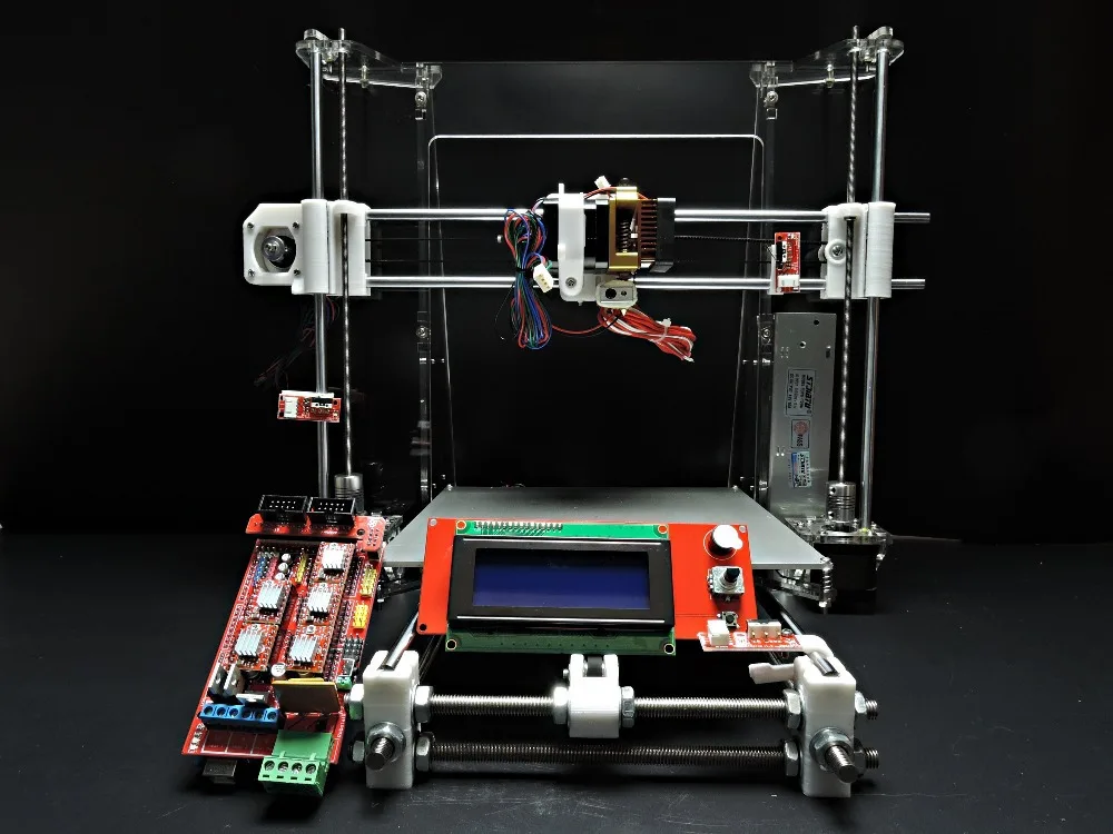
When building your first 3D printer, one of the most difficult tasks is choosing a control controller. There are enough controller boards on the market. There are expensive, there are not very expensive, high-quality and not very. To sort through everything, of course there is no opportunity and desire! So it is very important to choose the best option - simple with maximum software support.
CONTROLLER
There are a huge number of types of control controllers, as well as housings for RepRap. I chose, in my opinion, the most popular and available on e-bay:
1) controller - Arduino MEGA 2560 R3 ATmega2560;
2) power board - RAMPS 1. 4;
4;
3) stepper motor drivers - Pololu A4988;
4) interface board - RepRapDiscount Full Graphic Smart Controller (adapter included).ORDER
It seemed to me too expensive to buy boards in the original. Saving much on soldering, according to estimates, will also not work. Accordingly, the order was made on e-bay. At the same time, I was well aware that the boards could turn out to be of very mediocre quality. Took a risk! Three weeks of waiting, and the fees are in my hands.
TESTING
First of all, out of habit, the boards were subjected to a thorough visual inspection. The first fell into the hands of the Arduino MEGA 2560 R3 ATmega2560. It turned out to be of a very acceptable quality.
Behind it - RAMPS 1.4. And here is a huge disappointment - heavily oxidized (even rusted) contacts of the power connector.
At high currents, it seemed to me wrong to leave such a disgrace!!! I had to carefully unsolder the connector. It is blue in the photo. And solder a similar one found in the bins (green in the photo). Advice for those who come across this ambush - before soldering the connector housing, it is better to “bite” with side cutters . The contact pads of the board, and the conductors, are made quite well. The board successfully survived the “repair”. Before washing, I once again looked through the soldering. As a result, I found that there are a large number of solder balls around the pin contacts. I soaked the board in alcohol for 20 minutes and washed it well…
Then I tried to connect the power board to the controller. Out! But with great difficulty. Firstly, the reciprocal connectors do not match well :(. Secondly, the body of the controller power connector rested on the “leg” of the power connector of the power board (in the photo on the right) - had to bite off the “leg” with side cutters !
After installing the power board, I started mounting the stepper motor driver boards. The overall dimensions of these boards turned out to be too large and the boards interfered with each other!!! I had to work on a file. While I was turning the contours, the radiators fell off :) ... Either I'm not so lucky, or it's not clear what these radiators were installed on! Had to glue them in place with heat conductive adhesive.
After the "pleasant torment" with the power board in hand was the interface board. And here a marriage was discovered, which, after turning on the power, could lead to collapse! The indicator was soldered without installing racks and using a short connector. As a result, the housing of the LCD panel closed the contacts of the incoming connector!!!
For good, it would be nice to solder the indicator. But due to lack of time to look for a tall connector, PLS decided to temporarily install a folded piece of paper (pictured).
After I corrected all the jambs, I connected to the USB port - there was no flash with pops! So it's time to upload the firmware.
I stopped at the Marlin project. To my delight, the source codes are well commented out... Customizing the firmware is done by turning on/off the necessary descriptions in the source code. We configure, compile, flash, turn on.
The program has started. But due to the lack of a temperature sensor, I stopped at an error (at the bottom of the display). Found a suitable temperature sensor, installed. The controller is fully operational – “Mendel is ready”. Now it's time to connect the drives and test the connection to the computer. How to choose stepper drives can be found here. In my project, the ones shown in the photo below are used.After making sure that the electronic components of the board are working, we concentrate on assembling the printer case ...
ELECTRONICS POSITIONING
Housing assembled! Let's begin to scatter the electronics ... If everything was transparent enough with the case, then we had to think thoroughly about the placement of electronic components. After reviewing a large number of instructions for assembling such printers, I was struck by the lack of information in them on how to place the electronics and, last but not least, how to pull the wires.
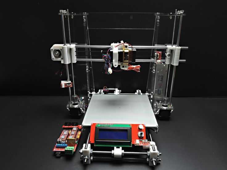 I didn’t want to leave it to chance and hang wires indiscriminately. Free "hanging" of wires can lead to the most unpredictable consequences.
 POWER SUPPLY AND CONTROL BOARDS
The power supply, as in the bulk of such devices, is located on the right side rack of the frame. I made the mounting holes in place, measuring the location of the PSU mounting holes. Here I want to note that I came across a fairly successful PSU. 250W of power in a relatively small package.
I placed the assembly of boards on the left side post. On all boards, the mounting holes are so closely spaced that the conductors are even under the head of the screw. For this reason, I had to cut racks and washers for attaching boards from silicone hose. To speed up the process, I used a regular adjustable wrench. I clamped the hose in it, pulled it out to the required length and cut it with a clerical knife.
I had to disassemble the assembly for marking. Further along the ARDUINO board, I marked out and drilled the mounting holes. Then I installed the ARDUINO board on the screws in the center of the board (there will be no access to them in the assembly).
 After that, I installed the RAMPS board and secured the remaining screws through the silicone standoffs and washers.
In order to safely run the power wires (12V) from the PSU, the wire from the motor of the Y, Z axes and the Y-axis limit switch to the board assembly, I preliminarily placed ordinary construction cable channels on the threaded studs.
ZERO POSITION SENSORS
Now is the time to install the “zero” limit switches. When choosing the option of mounting the limit switch board, I settled on the detail. The design seemed to me very convenient and did not check on the models. But in fact, it turned out that it is suitable only for the Z axis. I installed it on the Z axis. I used a stainless steel strip glued with a glue gun as shown in the photo as the axis limit switch sensor.
Next, I had to rack my brains for a long time over how to install the limit switches on the Y and X axes. It turned out to be easier with the Y axis - I managed to adapt the holder, which I installed on the Z axis. I fixed it with ties to the threaded stud. I also installed a strip of thin stainless steel as a sensor. In this option, it is not possible to adjust the position of the limit switch actuation (it is determined by the length of the sensor itself).
But I had to tinker with the installation of the X limit switch! To begin with, I made an adapter from textolite.
Then I made the mounting holes M3 in the DRIVE HOLDER, installed the limit switch and adjusted its position. The sensor was again made from a strip of stainless steel, which I screwed from the bottom of the EXTRUDER HOLDER (it is permissible to glue it with a glue gun).DESK HEATER
Before installing the heater board (hereinafter referred to as the heater), I thought for a long time how to start the cable channel.
 Having studied the design of similar printers, I realized that the “harness” of wires from the table was made quite unsuccessfully everywhere due to touching the frame parts. In my version, I excluded this moment (it will be seen in the photos below).
First of all, I put heat shrink on both ends of the prepared cable channel. In my opinion, heat shrinking gives rigidity to the cable channel. I fixed one end to the table holder with ties as shown in the photo.
After receiving the heater board, I did not examine it in detail. But before installation, I decided to inspect with passion the quality of the installation of wires. The result of the inspection was the decision to solder the wires - the wires were with obvious breaks in the cores and poorly tinned ... In a situation where the movement of the table is expected and, as a result, possible bends at the soldering point, a high-quality connection is necessary!Unsoldered the wires, cut off the damaged tails and, having warmed up well, tinned.
 It is necessary to warm up so that the wire is tinned not only in the cleaned area, but also under the braid. I soldered the wires in place and washed off the remaining flux well with alcohol.
Next, I moved on to mounting the table temperature sensor. At this stage, it is important to carefully solder the wires (in my case, this is MGTF) and mold the leads without damaging the cases. The sensor is installed in a hole in the center of the heater and secured with strips of kapton tape. At this stage, it is necessary to check that the sensor does not protrude beyond the level of the heater board and that the leads are securely fixed with adhesive tape without short circuits.Then ran the wires from the temperature sensor into the installed conduit and installed the heater board in place. It turned out to be more convenient to lead the heater wires into the cable channel from the side as shown in the photo.
It's time to pile up the wires coming from the extruder. This knot did not cause any particular difficulties. The only thing is that I did not initially stretch the wires for the fan! But with my extruder, you will need as many as two fans. I will talk about this in the article “WORKING ON ERRORS”. It is possible to fix the cable channel very conveniently as shown in the photographs. When fastening according to the proposed scheme, it will not be necessary to drill additional holes ...Mounted the cable ducts on the left post. At this stage, you will need to tinker with a drill. How everything is fixed can be seen in the photos below.
The last photo clearly shows how the cable channel of the table is positioned. As I said before, I managed to place it in such a way that it does not touch the parts of the printer when the table moves. The same can be said about the remaining cable channels.
All the wires are in place - you can start connecting them to the board. It took a little patience and attention to get everything connected exactly as shown in the diagram above! The only point that does not coincide with the diagram is the use of optical position sensors. It is necessary to take into account one more line - the power supply of the sensor (the board has a contact on the same connector).
All wires are in place - you can proceed to the firmware and calibration of the printer.ASSEMBLY KIT
The complete electronics kit is available in the online store at http://www.zdvstore.ru/prusa-electronic/.
The kit includes a controller board containing firmware that takes into account all the features described in my articles. By installing this set of electronics, you will immediately start the printer ...QUALITY OF SPARE PARTS WITH ALIEXPRESS (UPDATE FROM 01-04-2016)
After visiting my online store, I am often asked about the “overpriced” cost of electronics on its counter! I am ready to answer this question.
When buying electronics for my first printer, I got quite good copies for myself (with the exception of the RAMPs power board :). The secondary purchase of a small batch of components horrified me !!!
And for over a year now I have been trying to find a good electronics supplier in China. For adequate money, I could not find the right product.
To be honest, only the Arduino MEGA 2560 R3 ATmega2560 and the MK2B DUAL POWER table heater come in proper form with a few exceptions. With the rest of the boards, well, it's just a TROUBLE! This is especially true for RAMPs v1.4 boards and DRV8825 stepper motor drivers. Regardless of the seller, approximately the following items are received:
The most common jamb with a huge amount of spring a lot of sprout smeared along the Pajal Masic; in the fact that recently they began to put connectors with steel-colored contacts on the boards.
 These contacts do not even "want" to be tinned!I'm not talking about the normal soldering of contacts.This especially applies to stepper motor drivers.Further there are all sorts of "fun", starting with inverted connectors (pictured above :), ending with incorrectly soldered potentiometers on indicator boards.0003
 In a word, I have to spend a lot of time cleaning solder, soldering connectors, fixing jambs and washing boards!
I hope that I gave an exhaustive answer to the question :)!?
HOW RAMPS DIE WITH ALIEXPRESS (UPDATE FROM 04/27/2016)
At the beginning of the article it is described how I soldered defective power connectors on the RAMPs board. Let me remind you that these were connectors for connecting the heating elements of the hot ends and the table. The input power connector seemed quite decent to me :).
A little more than a year has passed… And… At the most “opportune” moment, during the printing of an urgent order, the temperature protection of the firmware is triggered! Printer stops in the middle of a part.

Learn more


