3D printer leg
3D printing prosthetics in 2022: The great revolution
3D Learning Hub
See all categories
Contents:
- Introduction
- Overview of 3D printing in the medical sector
- Why is using 3D printing for prosthetics so interesting?
- They used 3D printing to develop prosthetics
- What is next?
Introduction
Overview of 3D printing in the medical sector
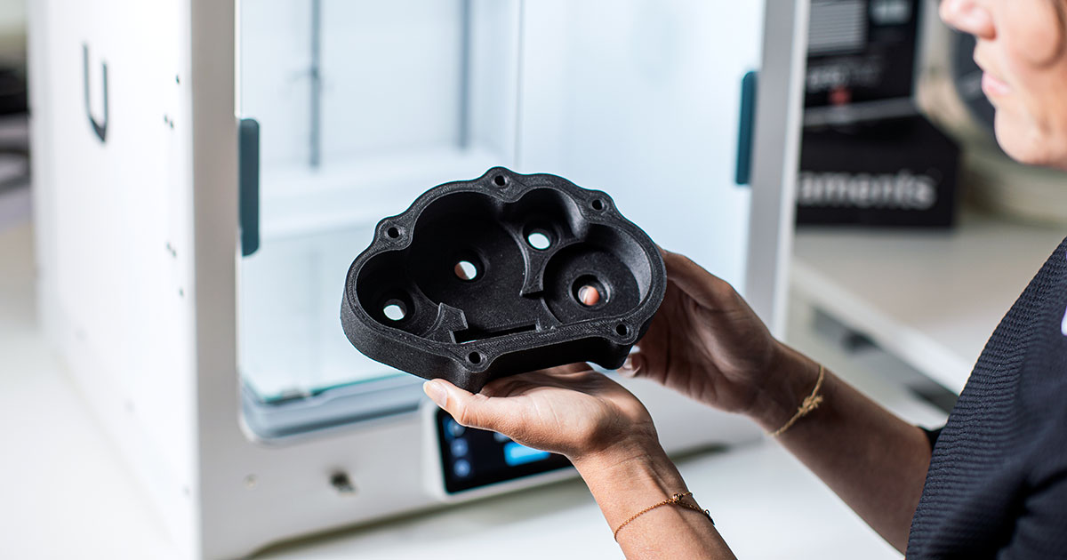
The medical sector benefits from the wide range of advantages offered by Additive Manufacturing. Thanks to the mass-customization opportunities and the flexibility of the manufacturing and design processes, 3D printing becomes a real alternative for this sector. In the future, this manufacturing technology could be used to replace human organ transplants, significantly speed-up surgical procedures, but also produce cheaper and more adaptable versions of required surgical tools. Using technology to rethink and improve the way we produce medical devices leads to great opportunities.
This technology can also improve the lives of those reliant on prosthetic limbs. That is a fact, we can notice a growing interest in adapted orthopedic insoles, orthosis, and prosthetics manufactured using additive manufacturing.
Why is using 3D printing for prosthetics so interesting?
Manufacturing prosthetic is expensive
Thanks to the constant evolution of 3D printing technologies, the medical industry is facing new challenges. In its own way, 3D printing is revolutionizing the field of rehabilitative medicine and tackling a particular issue: prosthetics. According to NGO LIMBS, only 5% of the nearly 40 million amputees in the developing world have access to prosthetic devices or assistance. Many companies such as Unyq are using the advantages of generative design and additive manufacturing to create a brand new approach to prosthetics both in terms of form and functionality. Indeed, some companies are focusing on bringing these advantages to the developing world, to the amputees in environments that lack the medical infrastructure or resources. The goal here is to support the labor-intensive and expensive prospect of traditional prosthetic manufacturing.
Manufacturing adapted and quality devices for amputees is actually a struggle all over the world, as these prosthetics are expensive and most of the time, poorly adapted to the patient’s particularities. New technologies such as this one can also be a major advantage for prosthetists, helping them in the development of customizable prostheses. From the creation of 3D printed prosthetic hands to functional wrists, solutions can be offered with additive manufacturing. Engineers and researchers are opening new possibilities for prosthetics
Advantages of 3D printing prosthetics
- Innovation: Innovate without worrying about the limitations of traditional manufacturing
Thanks to 3D printers, rapid prototyping has never been so easy. Iterate your ideas and projects faster thanks to this technology. Going further than traditional prosthetics manufacturing will enable great future developments.
- Customization: Create adapted prosthetics
The customization part is the most important argument here. Getting adapted devices and prosthetics will benefit the patients and improve their quality of life during a limb loss. Customizable functional prostheses creation is now possible thanks to 3D printers.
- Cost: Why are 3D printed prosthetics cheaper?
Once again, developing such a complex project as prosthetics is expensive with traditional manufacturing techniques. Especially if you want to adapt it to the morphology of the patient, additive manufacturing appears to be the most efficient technique to get low-cost prosthetics. It is becoming a life-changing solution to produce prosthetics in areas where the access to such devices is complicated, or impossible.
No minimum of order, no need to build an expensive mold, you only need a 3D file to print your project. Prosthetics are better, and more efficient while custom-made. However, customization is quite expensive with traditional manufacturing.
They used 3D printing to develop prosthetics
Several 3D printed prosthetics projects have already been developed all around the world. See how 3D printing materials and technologies are helping to create functional artificial limbs. Here are a few examples of 3D printed prosthetics:
3D printed prosthetic arm providing feedbacks
Lorenzo Spreafico is a student at the University of Leeds. He created a prosthetic arm with vibrotactile feedback.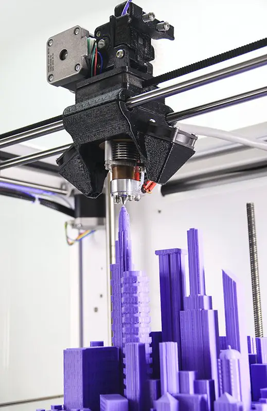 The student implemented pressure sensors at the tip of each finger of the prosthesis, this means the amputee can feel when they’re touching something. This prosthetic arm is his final year project in the Product Design bachelors at the University of Leeds in the UK. Thanks to additive manufacturing, Lorenzo Spreafico was able to lower the price of the device! The first prototype, called T1 is under €3,500. The student explains: “There is a huge gap in the development of prostheses: although we are developing extremely advanced technology to simulate human movement and dexterity, there is much less work done when it comes to simulating human touch“.
 Hand prosthetics
This might not come as a surprise to you, but it is a topic worth mentioning. According to research done by Amputee Coalition, on average there is an amputation done every 30 seconds, and life after such a procedure is hard. But there are people out there using the latest technology innovations to help others. E-nable is a global network of passionate volunteers who help amputees.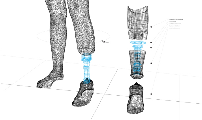 Thanks to 3D printing, amputees can have a new E-nable device in a short amount of time. The prosthetic hand is fully customized, matching the limb of the user, costs only a fraction of normal prosthetic costs, and dramatically improves the life of the amputee. Bringing all those aspects together in one product was impossible before Additive Manufacturing. Prosthetics are either cheap, but not functional and not personalized, or personalized and very expensive and they always take a lot of time to produce. 3D printing is truly changing the world of medicine and engineering.
 Leg prosthetics
Looking absolutely stunning and even impossible Exo by William Root breaks the boundaries of logic. He brings a new level of the esthetics of prostheses. His prosthetic leg is not only beautiful but also fully functional. First of all the designer improved the time-consuming process of manufacturing a prosthesis. Normally, the amputee had to have a mold done of his limb, then a cast was made, vacuum form, check for fit, assembly, and then adjustments were done.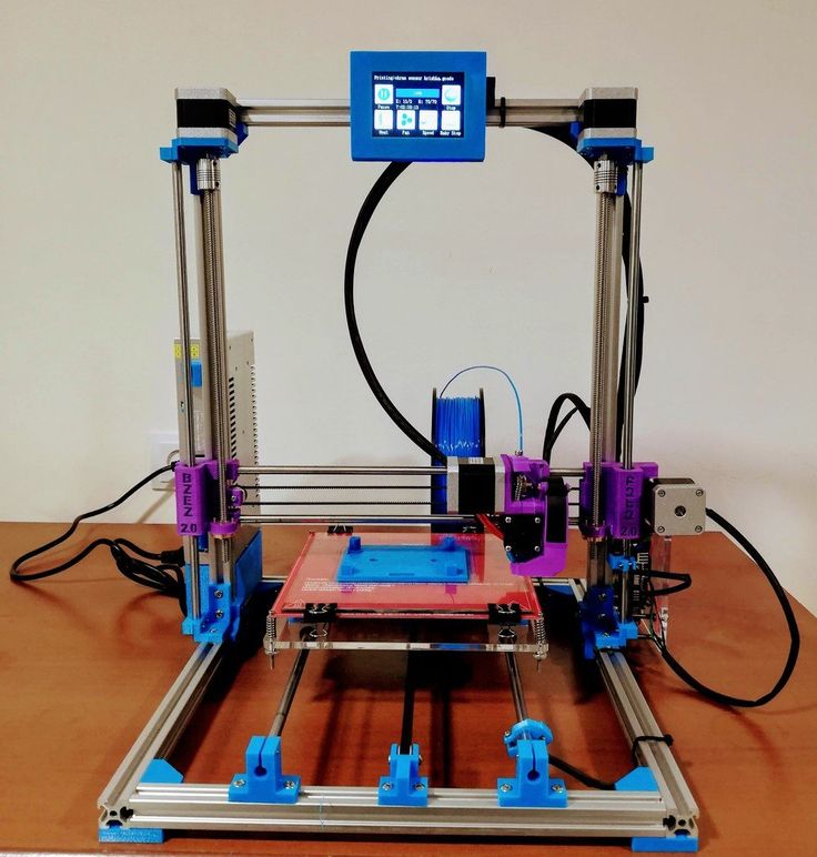 Of course, the tedious process has to be repeated again until the fit is just right. When it comes to 3D printing, you scan the limb, adjust the 3D model, and then print the design. Simple, fast, and effective. And in addition to that, it is beautiful. The prosthesis can be fully customized for the user, comfortable, and expressing their character.
 Hero Arm
Hero Arm is a project developed by Open Bionics, who aims to turn disabilities into superpowers with 3D printed bionic arms for children and adults. Using Selective Laser Sintering 3D printing, with Nylon PA12, they develop prosthetics covers inspired by superheroes such as Iron Man, or fictional universes such as Star-Wars or Frozen.Manufacturing prosthetics in remote areas
Guillermo Martínez is the founder of Ayúdame3D, he went from building robots to building prosthetics hands. At first, it was just for fun, and now, Guillermo Martínez helps people in Kenya by developing prosthetic limbs helping amputees living a more normal life. The founder explains : “I went there, tested out the prostheses, and saw that people were getting to grips with it quickly after using it. It felt great. I considered stopping there, but I loved the feeling of being able to help others so much that I decided to start Ayúdame3D.” (Source Business Insider) Resources in Kenya are limited, Guillermo Martinez managed to create hands costing only $50 thanks to 3D printing.
 Millie: the first-ever dog with a 3D printed prosthetic leg in Australia
People are not the only ones whose lives changed thanks to Additive Manufacturing. We already talked about a few animals such as a penguin and a duck with a prosthesis, now it’s time for Millie, the greyhound from Australia. She’s a rescue dog, which was kicked out because of a bad paw. Unfortunately, professional prosthetics cost 10 000$ and they are not as personalized. The owners turned to Autodesk, a leader in 3D modeling and CAD software. With Fusion 360 they designed a new, ideally-fitting prosthesis and then 3D printed it.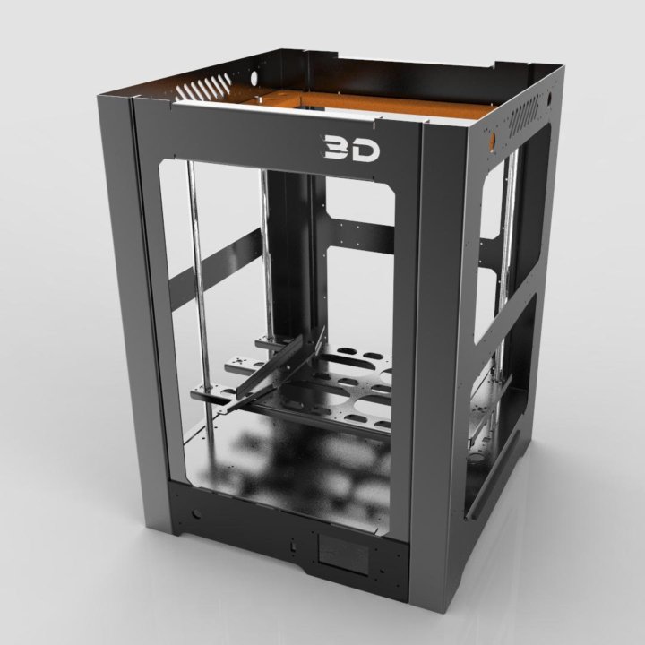 Most of all, 3D printed prosthesis matches exactly the needs of Mille and her limb. It doesn’t cause her any discomfort and allows her to play and be a happy pup. It was also a quick process, and on top of everything was much cheaper.
What is next?
The future of 3D printed prosthetics
It is definitely bright! As you’ve seen in this article, the presented examples show how beneficial Additive Manufacturing is to the medical industry. 3D printing prosthetics are cheaper by thousands of dollars. They are also much more comfortable, fitting exactly the limb, not causing pain to the user, and they are highly customized. This level of personalization has never been achievable before.
Do you have a prosthetics manufacturing project?
Using an online service bureau such as Sculpteo, there is no minimum order quantity, from a single object to 10 000+ parts, you can 3D print the exact amount of parts you need. With 10+ years of expertise in additive manufacturing for production and prototyping, Sculpteo is also offering rigorous quality control.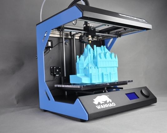 With our online 3D printing service, you get professional 3D printing at your fingertips with +75 materials and finishes to develop your most ambitious projects, such as prosthetics. We’ll take care of the rest in our industrial ISO 9001 factory.
Upload your 3D file and get your free instant quote!
Any question? Feel free to contact us to discuss your project, our 3D printing expert are here to help you develop your project.
Related Topics
- Return to Top
Get the latest 3D printing news delivered right to your inbox
Subscribe to our weekly newsletter to hear about the latest 3D printing technologies, applications, materials, and software.
Researchers Create Perfect Fitting 3D Printed Transtibial Leg Socket for Prosthetic Legs - 3DPrint.com
I am fortunate enough to have both of my legs. I can run, jump, play football, and swim in the ocean.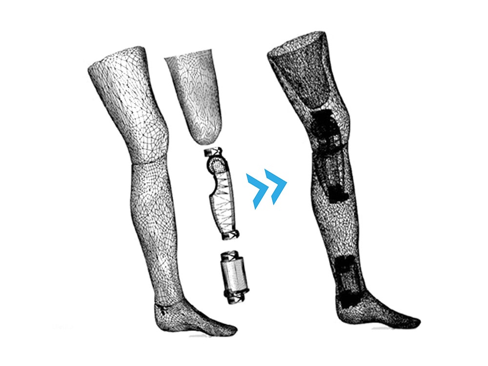 Unfortunately though, not everyone can say the same. There are individuals born with birth defects that bring them into this world with missing legs, and there are those who suffer an accident or disease which leave them missing one of their legs. Prosthetic legs have been increasing in popularity, and they have really been quite effective in providing amputees and others with missing legs, the opportunity to walk again.
I’ve spoken to many people over the years who use prosthetic legs. While they are typically pleased with the fact that they can now get around without the need for a wheelchair or crutches, there are still plenty of qualms on their behalf.
Quite simply put, it is usually a massive pain in the butt getting fitted for a prosthesis. This is because of the lack of customization provided by today’s sockets. The socket is the part of the prosthesis that meets the “stub” of the wearer’s leg. Usually it takes several fittings and adjustments, followed by several more, before a prosthetic leg will fit just right.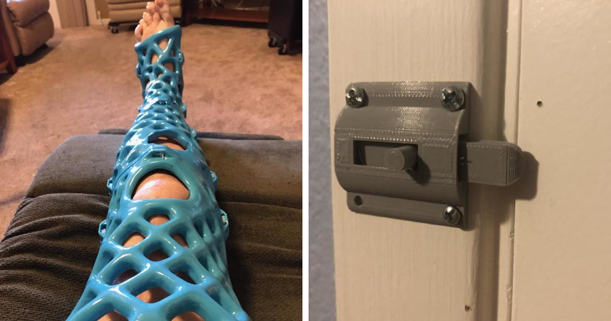 Even then, “just right” is a term that can be overstated, as many times the fit never ends up being perfect.
For one biomedical engineer, named Lizbeth López, this simply was not enough. López has been working at Tec de Monterrey, in Monterrey City, Mexico under the guidance of her thesis advisor, Dr. Ciro Rodriguez. In a collaboration with Ottobock and cTI Renato Archer in Campinas, Brazil with Dr. Jorge V. Lopes’ guidance as well, López set out to create a 3D printed custom transtibial leg socket that fits just right.
“The main objective of this work was to fabricate a complete functional prosthesis, in this case oriented to transtibial amputees as the first group of test patients,” López tells 3DPrint.com. “The project began as a personal motivation to design and fabricate prosthesis well adapted to health needs of the patient.”
López and her team worked with two patients. One of these patients was in Mexico, and López was able to test the use of laser scanners and computer tomography in order to create many different iterations in several different types of software. This allowed her to choose the best option that she would use in order to begin 3D printing the transtibial socket, with hopes of it being used on a final prosthesis.
López then moved her research from Mexico to Brazil and started working with a second patient, in compliance with Ottobock.
“We decided to use a laser scanner and CT to capture the stump of the patient,” López explained. “Later the DICOM data from [the] CT was reconstructed as a 3D structure in InVesalius software, and then it was compared with data acquired from the laser scanner. Subsequently, we imported the files in .stl extension to CAD software to begin the process of design, based on the real anatomical data of the specific patient.”
One of the tremendous benefits of using this 3D data to create the socket, other than the customizability it provides, is that once the scans are taken, there really is no need to directly work with the patient any long, prior to the initial fitting. Once the team believed that they had the socket designed correctly, they had to put it through tests to ensure reliability.
“We tested the socket design with FEM analysis, just to make sure that load conditions were to show numerical results under the yield strength of material; so we can be confident about the mechanical resistance of [the] 3D printed socket before the patient tests it,” explained López.
Once the tests were complete, it was on to 3D printing the socket using an SLS HiQ 3D printer. Printed in polyamide, the process took about 17 hours to complete. The socket was then mounted and aligned to the complete prosthesis at Ottobock in Valinhos, Brazil, before the ultimate test was undertaken.
The prosthesis and this incredible 3D printed socket were fitted to the patient, and the results surprised just about everyone. The patient, who has been involved in many other prosthetic leg tests for Ottobock, couldn’t believe the results. The socket was completely comfortable from the first time he put it on, only requiring the adjustment of one single screw. In the past, this same patient was required to try on the same prosthesis over and over again in order to get just the right fit. This could take days between fittings, causing quite a bit of frustration and aggravation.
With 3D printing technology and the tremendous work of López and her team, no adjustments were required.
“Technical [personnel at] Ottobock pointed [out] that this kind of result is not seen every day,” explained López. “That’s really good because then we have a great approximation to the fantastic and ‘futuristic’ idea that it’s going be possible to adapt many prosthesis to many patients in one single day.”
3D printing is certainly showing its potential in the field of prostheses, allowing for complete customization on a one-to-one basis, making the entire process much faster and more efficient, leaving both patient and doctor happy.
What do you think about this potential that 3D printing has in the custom fitting of prostheses? Discuss in the 3D printed prosthetic leg socket forum thread on 3DPB.com. Check out the video provided to us below of López’s patient trying on his prosthetic leg.
Stay up-to-date on all the latest news from the 3D printing industry and receive information and offers from third party vendors.
Tagged with: 3d printed prostheses • 3d printed prosthetic leg • brazil • Mexico • ottobock • prosthetic leg socket • Tec de Monterrey • transtibial leg socket
Please enable JavaScript to view the comments powered by Disqus.
8 3D printing options to help you get rid of the elephant leg.
What is an elephant leg in 3D printing? 8 ways to get rid of an elephant leg in 3D printing.
1. 3D printer bed calibration. 2. Reducing the temperature of the printing platform. 3. Install the cooling of the first layer. 4. Increase the first layer print time. 5. Reduce the flow rate of the first layer. 6. Adding a raft to your model. 7. Use of chamfers in models. 8. Elephant leg compensation in the slicer. nine0003
Output.
In the world of 3D printing, such a defect as an “elephant leg” is quite common, and in our opinion it is not given enough attention.
For most 3D printing applications, this disadvantage can be ignored, as it does not greatly affect the final result.
However, when it comes to practical applications, the elephant's foot can present serious problems. This defect sharply reduces tolerances, which makes it much more difficult to fit parts to each other. nine0003
For example, you want to fit one piece to another, but you run into a problem because the first layer is much larger than the next.
In the architectural field, engineers can use 3D printing to check and determine the accuracy of a design before it is manufactured on a significant and costly scale. If there is a defect in the print, it distorts the representation of the final product.
For example, if a civil engineer is designing a building and the printout is faulty, it will not display the structure of the building correctly. nine0003
We have been providing 3D printing services for several years, and the presence of an elephant leg for most of our clients' projects is an unacceptable defect.
We hope that with our preface we have convinced you that it is still worth getting rid of the elephant's foot. And in this post, we will introduce you to the basic ways to fix this problem.
Some of our recommendations may seem difficult for beginners. But it's actually much harder NOT to know what to do than it is to have a clear step-by-step guide. nine0003
What is an elephant leg in 3D printing?
Elephant foot is a deformation of a 3D model caused by the temperature and weight of the model.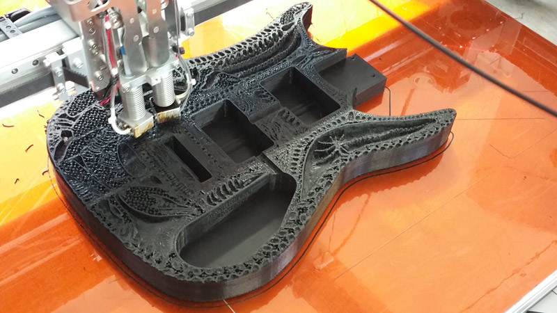
The upper layers put pressure on the first layer, which has not yet cooled down, and under the influence of the mass of the object, the first layer is flattened, and its geometry is distorted. Accordingly, the higher your model, the more the effect of the elephant's foot is manifested.
In our blog, we have repeatedly mentioned that printing the first layer and calibrating the platform are critical to obtaining quality prints. And, describing the causes and ways to eliminate the elephant's foot, we are again forced to return to this topic. nine0003
8 ways to get rid of an elephant leg in 3D printing.
Of all the many limitations and challenges users face with 3D printing, the elephant leg remains one of the easiest to solve. You just need to run a few test operations to determine which factor in your case is causing this effect.
1. 3D printer bed calibration.
Fixing almost any 3D printing problem starts with platform calibration. And the elephant leg is no exception. nine0003
This effect may be due to an incorrectly calibrated table or an incorrectly set nozzle height.
Positioning the nozzle too close to the 3D printer bed causes the first layer to be pushed too far into the bed and flatten out.
The principle of calibration is that the nozzle is at the same distance from the platform over the entire working area of the printer.
Also, as is often the case in 3D printing, properly leveling the platform can generally improve the print quality of your projects. nine0003
Calibration of the 3D printer bed is a key factor in 3D printing and can eliminate many 3D printing problems.
2. Reducing the temperature of the print platform.
High table temperature does not allow the layer to cool sufficiently.
The fusing of subsequent layers of the part on it leads to squeezing of the object and the appearance of an elephant's leg.
Normally the table temperature is set according to the recommendations of the plastic manufacturers. Properly selected temperature ensures good adhesion of the layer to the platform. nine0003
If you are experiencing the elephant foot effect, try lowering the temperature of the platform.
Do not rush this process. It is recommended that you gradually reduce the temperature by 5°C until you start getting good quality prints.
If you have reached the minimum recommended temperature for the platform and the problem persists, there is likely another reason for your elephant foot and you should consider other options.
3. Install the first layer cooling. nine0041
Most slicers have cooling of the first layers disabled by default. Turning off the fans on the first layer ensures good adhesion of the part to the platform.
But we have already found out that the elephant's foot appears when the first layer does not have time to cool.
Increasing the initial fan speed to 5% or 10% will cool the filament faster and prevent flattening of the initial layer.
We recommend using a 3D printing varnish to improve adhesion. nine0003
4. Increase the time to print the first layer.
Increasing the initial layer print time is also a cooling solution, but instead of activating/increasing the fan speed or lowering the table temperature, we set the first layer print speed to be slow.
This will give it time to cool down before the printer starts printing the 2nd layer.
If the first layer has not had time to cool down, then applying the second layer compresses the first layer. This issue can also cause your part to be sized incorrectly not only horizontally but also vertically. nine0003
It is also clear that the use of quality 3D printer filament with the same diameter along the entire length ensures uniform extrusion and reduces the likelihood of elephant's foot.
5. Reduce the flow rate of the first layer.
Your printer may be set to over-extrusion and extrude too much plastic on the initial layers. Excessive extrusion may also be due to your nozzle being too close to the platform. We mentioned this in the first paragraph of our guide. nine0003
You can calibrate your printer using our guide to setting extruder pitches.
How to calibrate the extruder steps (E-steps).
Or you can simply reduce the flow rate of the first layer to 95%. This will not have any effect on the adhesion of the first layer, but will affect the elephant's foot.
6. Adding a raft to your model.
A raft is a horizontal mesh created by placing strands of plastic on a platform.
Since the elephant foot problem occurs between the working platform and the first layer, the raft will take the hit. nine0003
This will certainly get rid of your elephant's foot, but it's more of a workaround than a solution.
Using this option you will get a rough surface on your part and you will have to spend some time removing the raft. However, you can consider this as a useful alternative, especially in cases where you need to place one part inside another.
7. Use of chamfers in models.
There are times when getting rid of elephant legs is not possible at all. All options seem to be unable to provide the expected results. nine0003
If setting up and calibrating the printer is a tedious process for you, and a slight change in the 3D model seems to be an easier way, then choose this option.
All you have to do is add a small 45° chamfer to the bottom of your model. The figure shows two identical parts. Left part with chamfer, right without.
Any modeling software has a set of functions for creating a bevel and usually it does not take much time. nine0003
The top layers will weigh down on the first layer, and the chamfer will compensate for the elephant's foot in your print.
8. Elephant leg compensation in slicer.
An even easier way to get rid of an elephant's foot is to compensate with a slicer. Cura, one of the most popular and widely used slicers, has incorporated this setting into its software.
This parameter is called initial layer horizontal expansion (horizontal expansion of the first layer), located in the section Shell (Walls). nine0003
You can also easily find it by entering the word elephant or elephant in the Russian version in the search bar.
In Slic3r and PrusaSlicer this parameter is called Elephant foot compensation.
In Slic3r you can find this setting here: Print Settings tab -> Advanced settings
In PrusaSlicer the setting is under Print settings - Advanced - Elephant foot compensation. PrusaSlicer must be in advanced or expert mode to access this setting. nine0003
Simplify3D has a "horizontal size compensation" setting. By default it applies to all layers, but you can limit it to only print the first layer.
To calculate the correct compensation value, we recommend that you print a test cube. After printing, measure the dimensions of your cube at the top and bottom.
Assume that the cube measures 20.02 mm at the top and 20. 3 mm at the bottom (elephant's foot).
To calculate the compensation factor, plug these values into the following formula:
(20.02-20.3)/2=-0.14.
We got a negative value, and this is what we need to set in the slicer. In fact, this method creates a chamfer without changing the model itself, but with the help of a slicer.
Conclusion.
Elephant foot on a 3D printer is a common mistake that is easy to fix.
In this post, we have described several approaches that will help you achieve the best possible results.
It is important to understand that steps 1-5 really solve the elephant's foot problem, while steps 6-8 just cover it up. nine0003
Using a raft will get rid of the elephant's foot, but you will spend more time and materials and will not get a smooth surface of the bottom layer.
We recommend that you first try simpler solutions that do not take much time.
If you have identified the cause that causes the elephant leg defect, then use a specific solution aimed at eliminating the cause.
Problems like the elephant's foot may interfere with motivation for a while, but they cannot stop those who are focused enough on achieving expected results. nine0003
With a little testing and patience, not only will you get quality prints, but you will gain additional experience that will help you with other 3D printing tasks as well.
If you want to unlock the hidden possibilities of 3D printing, you have to solve these little problems yourself. Learn and grow by printing amazing designs.
Happy printing!
3d printing problem. Elephant foot
3DPrintStory 3D printing process 3d printing problem. elephant leg
Hello everyone. Today we will touch on a fairly common, but somehow too little mentioned topic. This is elephant foot . One way or another, everyone has come across this, but most people simply give up on this problem, because they don’t know how to solve it and simply cut this deformation with a knife. But this is clearly wrong, so today I will tell you how to fix this whole thing, since it is quite simple. nine0003
First, let's look at why this deformation occurs at all. There are two options:
The table temperature is too high. Because of it, the model simply melts and the lower layers spread a little. This is solved by lowering the temperature of the table.
The second one is trickier and not so obvious, so here are some funny pictures for you. Conventionally, the plastic tracks are flattened when printing at the most common settings. Namely, at a layer height equal to half of the nozzle diameter. If everything happens as in the picture, then everything is fine and the tracks touch each other a little, holding the model together.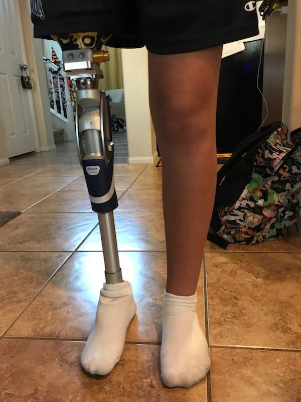 In this case, the geometry will be perfect. nine0003
| |
But let's see what happens if the distance from the nozzle is less than the layer thickness. There is the same amount of extruded plastic, but it has nowhere to go and the width of the tracks will increase. At the same time, neither the 3d printer nor the slicer knows about this and they will not correct the distance between the tracks, so the tracks will conflict with each other.
Here the intersection is shown in red. Naturally, this cannot be so, and the paths merge into a shapeless mess, mixing, spreading and forming ridges. Here I showed it very conditionally, but for understanding the processes it will do. If you look closely, you can see that these ridges and streaks go beyond the upper boundary of the layer and occupy part of the space under the next one. Naturally, he also cannot lay down as planned, as a result, the pattern repeats, albeit on a slightly smaller scale, again and again, until the ridge is no longer so small that their presence can be said not to affect the next layer and the model starts to print normally. nine0003
It also happens when the elephant leg ends with the layers of the bottom, which have one hundred percent filling. This case is the same eggs, side view, just the paths can spread as wide as they like and do not create ridges and, accordingly, do not affect the next layers.
So, when it is clear why this elephant's leg arises, we can safely offer three solutions.
- Increase the distance between the nozzle and the table on the first layer to match the one specified in the print settings. nine0227
- Decrease the feed on the first layer so that the tracks do not spread or clash.
- Tell the slicer how wide the track actually turns out so that he builds them into an even model.
Of course, the first option is the most correct and it can be implemented either through table calibration, which is quite laborious, or through setting the z offset in the print settings. This is an extremely useful setting in all popular slicers. In Cura she is in section sticking to the table, in simplify 3d on the tab g-code. It works very simply - it adds its value to all z coordinates in the model, or subtracts it if it is written with a minus. Therefore, if we have an elephant's leg, then we slightly increase this parameter until the moment when it does not pass.
I printed some calibration cubes to show how this setting works. In addition to him, nothing has changed not in the model, not in the settings. The first cube is printed with a z indent of 0, followed by 0.05 mm increments. nine0003
By the way, the same parameter can be used if the table is calibrated with too much clearance and the plastic does not stick. Just set it to a negative value.
The second method, I think, is not particularly correct, since with it the first layer is lower than necessary for the model. But in reality this can be neglected. The essence of the setup here will be - the creation of two different processes - one for the first layer with a lower feed, the other for the rest of the model. This is rather tedious compared to the indent setting, but nevertheless it has the right to exist in case for some reason it cannot be applied. I will explain using simply 3d as an example. First, we create a process for the first layer, reduce the flow value by, say, 20 percent, after which we go to the advanced tab and set it to stop printing at height equal to the layer thickness from the settings. In our case, 0.2. Next, we create another process with a normal flow and set the advanced tab to start printing at height, which is also equal to the layer height. That's it, there are two processes that together will cover the entire model, but have different settings. In our case, a different flow. Now we need to print some small test models and see. If there is an elephant leg, reduce it further, if not, stop or even slightly raise it in order to more accurately determine the ideal setting. nine0003
The third method, unfortunately, will not help if the elephant's leg is too large, but it works very well with a medium or small one. The point is to play around with the extrusion width settings of the first layer. By the way, many people think that if the value of this setting is reduced, then the tracks will become narrower, but in fact the opposite is true. In fact, this is not a control parameter, but a controlled parameter, that is, it is necessary to output to it what is actually obtained, and not what we want to receive. If we have a nozzle of 0.4 mm and the extrusion width is also 0.4 mm, and the tracks on the first layer of the clavicle are twice as wide, that is, 0.8, then we set the extrusion width of the first layer to 200 percent, that is, 0.8 divided by 0.4. As a result, the slicer itself will push the tracks apart so that, firstly, they line up on a flat surface along the outer perimeter, and secondly, they do not conflict with each other and, accordingly, do not bulge. In this case, the resolution of the first layer will be lower, as if printed with a nozzle with a larger diameter, but the plastic will be squeezed into the table, which in some situations can increase adhesion.


