3D printer gear generator
Gear Creator | MatterHackers
- Home
- Store
- MatterHackers Products
- MatterControl Slicer & Design Software
With Gear Creator you can seamlessly create perfect involute gears inside MatterControl. Just drag a gear object to the print bed and specify the Height, Tooth Count, and Pitch, and if you need more advanced features you can also adjust the Pressure Angle, Clearance and Backlash. When you need to create custom mechanical designs, Gear Creator is the perfect addition for MatterControl.
Remove from wishlist Add to wishlist loading...
Tagged: Software and Add-ons
Product No. M-ENZ-NGL4
| List Price: | $24.95 |
|---|---|
| Price: | $24.95 |
| Price: | $... |
| Order Now: | Ships calculating. |
Gear creator is the easiest and most complete way to create involute gears. It allows for the customization of Height, Tooth Count, Pitch, Pressure Angle, Clearance and Backlash.
Involute gears are the most common system used for gears in the world. They ensure that all gears, regardless of tooth count, mate together perfectly as long as they have the same Pressure Angle and Pitch. Involute gears ensure mating gears have a single line of force during the entire rotation of the gear. This mechanical property is critical for creating functional, long lasting gears.
Note: If you have a subscription to MatterControl Pro Gear Creator is already included.
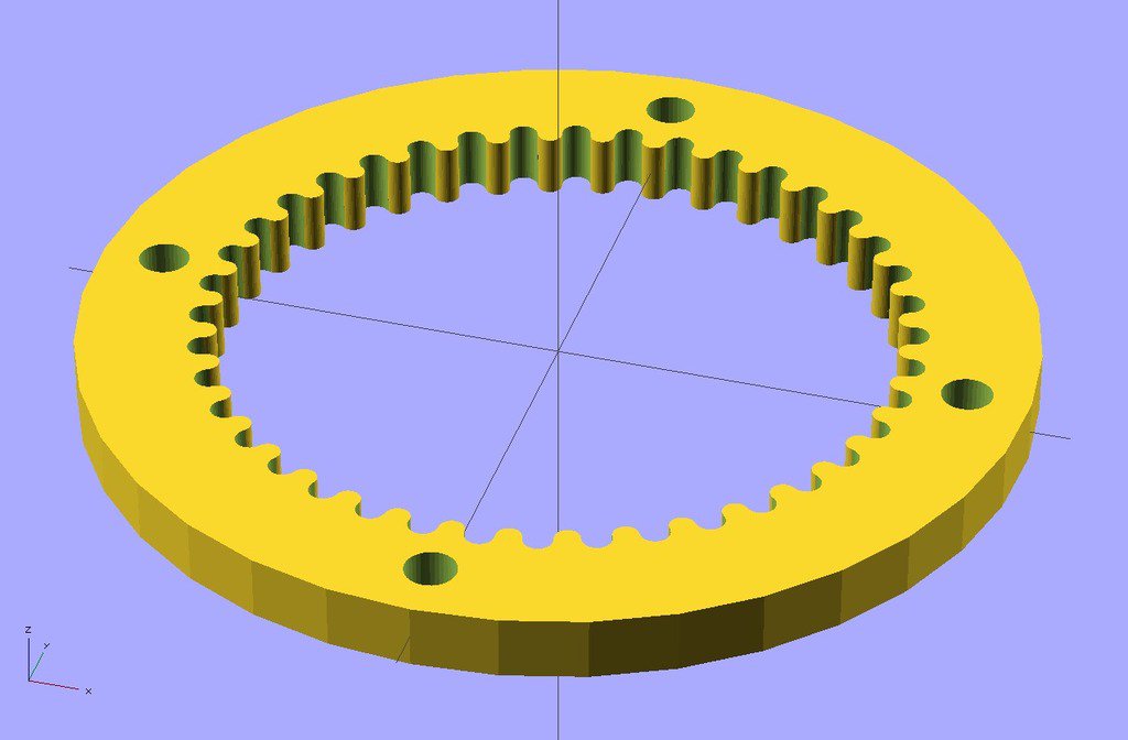
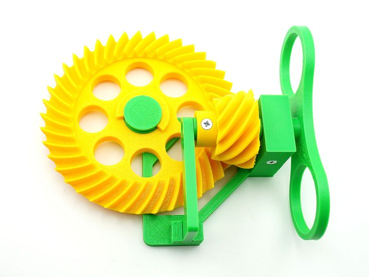
Just drag a gear object to the print bed and specify the Height, Tooth Count, and Pitch, and if you need more advanced features you can also adjust the Pressure Angle, Clearance and Backlash.When used with the other design tools of MatterControl very advanced gears can easily be created.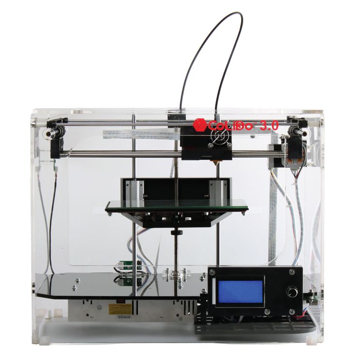 Below you can see the affect of adding a twist to two different gears. Each of these gears has had the twist operation set to a rotation distance of 5 and one of them has the rotation direction reversed. These types of advanced editing features can easily add to the utility of gears you can create for any project.
Here you can see two gears that have had a twist operation applied to them
MatterControl User Guide
Visit the MatterControl User Guide for more information and help with MatterControl. The guide is always being updated and should be useful for getting started.
MatterControl User Guide: https://www.matterhackers.com/mattercontrol/support
Recommended System
Windows 10: Windows represents the most stable and current version of MatterControl:
- Operating System: Windows 10
- Processor: 64bit, 3 gigahertz (GHz) or faster processor
- RAM: 6 GB
- Hard Disk Space: 100GB
- Graphics Card: DirectX 9 or later with WDDM 1.
 0 driver
 - Display: 1024 x 768 or higher
Download MatterControl
Download 2.0 (Windows)
Download 2.0 (Mac)
To enable Gear Creator:
- Install MatterControl
- Login to the account you purchased with
- You may need to logout and back in if Gear Creator is not unlocked
- You can find Gear Creator in the Library under Pro Tools
MatterControl Tutorials
Create more with MatterControl - MatterHackers own 3D design, prep and slice program for all your 3D printing needs. Whether you're a new MatterControl user, or looking for more in-depth knowledge on how to use MatterControl, these tutorials will get you on the right path.
▷ gear generator 3d models 【 STLFinder 】
Gear Generator
thingiverse
Gears that are varied in size and teeth amounts.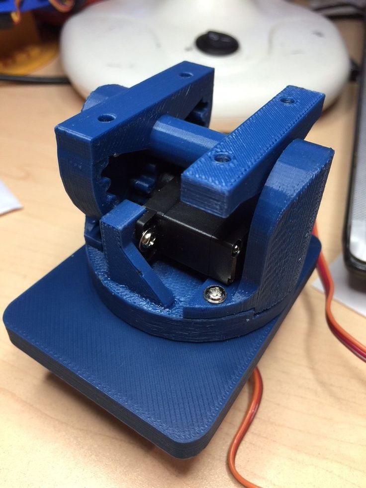
gear generator
thingiverse
a gear generator, creates involute and cycloidal gears, helical, straight and herringbone etc. ...some files may be missing let me know.
Gear generator
thingiverse
Gear generator. ...NOT MINE (thanks to author), just added it so it can be easily customized.
gear generator
grabcad
create gears in 3 easy steps:1. onbox the zip2. open the xls data -> put in your specifications3. ...Open the CATPart go on "Konstruktion" -> doubleclick on "Teilkreis" -> on the right side from the button Radius there is an icon ->.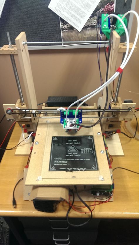 ..
..
Spur gear generator
grabcad
Spur gear generator
Involute Bevel Gear generator
pinshape
Summary Bevel Gear based on the fantastic gear generator. Tooth count ends up being specified teeth /2*sqr(2), though that will change based on the bevel angle. ...I printed some and they mesh properly.
Involute Bevel Gear generator
thingiverse
Bevel Gear based on the fantastic gear generator.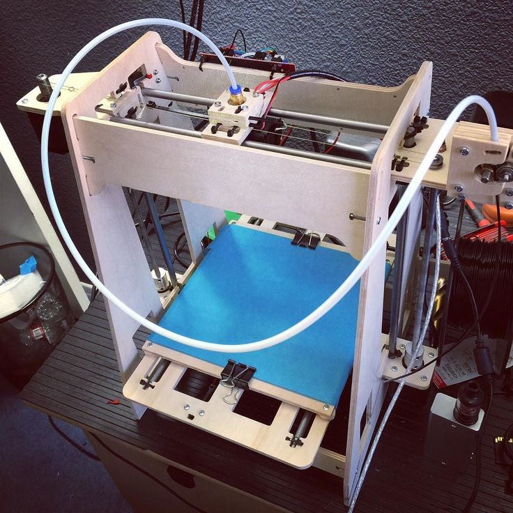 Tooth count ends up being specified teeth /2*sqr(2), though that will change based on the bevel angle.
I printed some and they mesh properly. ...
Tooth count ends up being specified teeth /2*sqr(2), though that will change based on the bevel angle.
I printed some and they mesh properly. ...
Involute Bevel Gear generator
prusaprinters
Bevel Gear based on the fantastic gear generator. ...Tooth count ends up being specified teeth /2*sqr(2), though that will change based on the bevel angle.<br/> I printed some and they mesh properly.</p>
Callable Gear Generator Remix
thingiverse
This is a remix of user Longrange's Gear Generator V2 https://www.thingiverse.com/thing:268787 Openscad is a free program required to edit and use this Gear generator to create STL files of gears or add to your Openscad project as a library. See...
Cycloidal gear generator
grabcad
Put values into GENERATOR.XLSX, open&save KOŁO, then open C7. ...Very handfull to start projecting new gear
Herringbone Gear Generator
pinshape
... gear. ... Angle sketch wraps around the cylinder to create a 3d sketch that is used to sweep the tooth. Angle sketch should stay the same for different gear tooth counts. v3 now includes a rack which meshes properly with the double helical gear.
Herringbone Gear Generator
prusaprinters
. .. the cylinder to create a 3d sketch that is used to sweep the tooth. Angle sketch should stay the same for different gear tooth counts. v3 now includes a rack which meshes properly with the double helical gear. Print instructionsCategory: Parts
Herringbone Gear Generator
thingiverse
Added the necessary aspects to make this a herringbone gear. Angle sketch wraps around the cylinder to create a 3d sketch that is used to sweep the tooth. Angle sketch should stay the same for different gear tooth counts. ...v3 now includes a rack...
Ekobots - Bevel gear generator.
pinshape
All parametric bevel gear generator in OpenSCAD. Attention: Only 45 degrees twins gears will math. You can try to correct they manually. The program use the internal and external diameter of the gears to create the teeth. Different number of...
Gear Generator 3D model
cgtrader
Gear Generator Houdini ver. 17.5. GameDevToolSet required! The generator randomly distributes points along a given plane, builds a path along the points, and based on this path creates the correct gear size with the centers at these points. Only the...
Ekobots - Bevel gear generator.
thingiverse
Bevel gear generator - All parametric. Attention: Only 45 degrees twins gears will math. You can try to adjust they manually. The program use the internal and external diameter of the gears to create the teeth. Different number of teeth, different...
Easy Bake Gear Generator
thingiverse
I wiped up a gear generator based on the MCAD 'involute_gears.scad' libarary Hopefully, this makes creating gears very easy since all you have to do is plug in some numbers and press F6. Options include: recessed sides (single or double sided) gear...
Parametric Herringbone Gear Generator
grabcad
An involute herringbone gear generator in Creo Parametric with adjustable diametral pitch, number of teeth, pressure angle, width (thickness), and herringbone twist angle.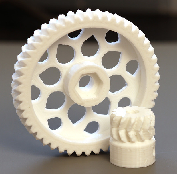 Open each of the two models, and go to model intent > parameters to...
Solidworks Gear Generator
thingiverse
Currently only does straight spur gears, but it's really easy in Sldwrks to make an internal or helical gear. I realize only a minority of people on this site use Solidworks. I use it a lot, and I'm all that matters in the end :) ...
Ekobots - Gear generator cylindrical tooth
pinshape
All parametric gear generator for cylindrical tooth in OpenSCAD: Internal gear, external gear and gear grub. I made it to solve problems with regular gears.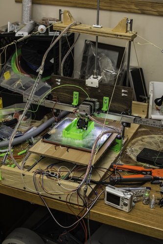 Regular gears don't work well with soft materials. Better tooth design for soft...
Ekobots - Gear generator cylindrical tooth
thingiverse
Gear generator with cylindrical tooth Internal gear; External gear; Grub generator; I made it to solve problems with regular gears. Regular gears don't work well with soft materials. Better cylindrical tooth design for soft materials(plastics, wood...
Spur and Helix Gear Generator
thingiverse
Instructions I have always wanted to build a spur gear generator, but have never figured out how actual gear dimensions were determined. I finally started drawing up sketches on paper, and from there I noticed some mathematical patterns. Using the...
Solidworks Small IPS Gear Generator
grabcad
... same for all meshing gears. Then click OK, it should rebuild automatically but if it doesn't, force it to rebuild using CTRL+B or Edit > Rebuild. You can also change the thickness of the gear using the variable "H" and the size of the hole "L".
Parametric Involute Spur Gear Generator
grabcad
An involute spur gear generator in Creo Parametric with adjustable diametral pitch, number of teeth, pressure angle, and width (thickness)Go to model intent > parameters to customizeRegenerate the model to updateDefault bore is 1/2 hex, but it can. ..
..
Robust Involute Helical Gear Generator
grabcad
For modeling a TRUE Involute Spur Gear in Solidworks This template is built with some "IF" "THEN" statements So it can handle a wider range of user inputs for " Number of Teeth. This is with the Gullet of the first tooth cut on the "Y" axis Note:...
Gear Generator Bidon Generator
sketchfab
No description provided.
Exact Gear Path Generator
thingiverse
. .. gear by applying a balanced absolute value rotation to copies of the gear along the Z axis. An example planetary gear set, featuring herringbone "inner" and "outer" gears is provided to demonstrate the power of a path-based gear generator.
Gear Path Generator
thingiverse
Update (2016-Jan-19): The OpenSCAD version of the involute gear tooth generator is complete (with addendum, offset, and involute diameter settings), and the path rotation has been included. Now it's just a matter of sorting out the maths so that...
Gear Path Generator
prusaprinters
... It cuts the curve into tiny pieces to calculate angles and lengths for the gears, so a smooth function should give reasonable results.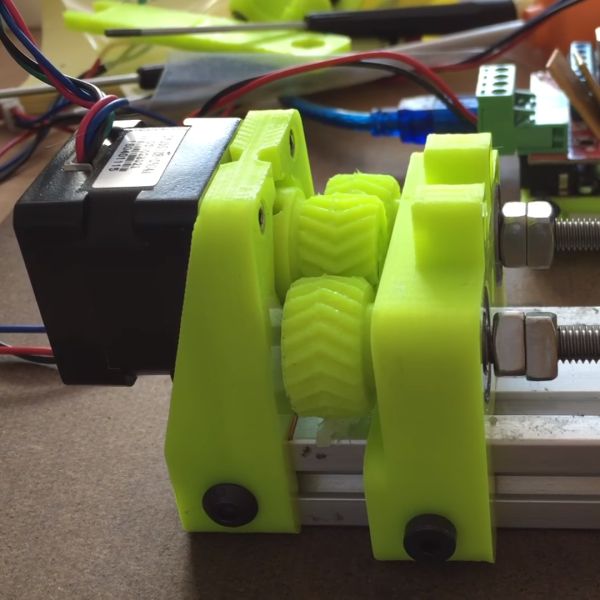 Sizes are scaled based on the 'radius' value so that the circular gear generator will still work. Category: Other
Gear Profile Generator
thingiverse
This is a spreadsheet that will generate a list of points for half a gear tooth (image shows CAD result for 3 teeth) depending on the number of teeth, pressure angle and profile offset. From there you can load it into your CAD software of choice. ... ...
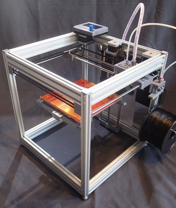
from which to print small gears, material of manufacture
One of the advantages of 3D printers is uniformity. A novice printer can easily replace any part. Moreover, he does not have to go to the store or order an item from China. He can do all the details himself. Of particular value is the printing of gears. This is the “working” unit of the device, which is most prone to breakage and wear.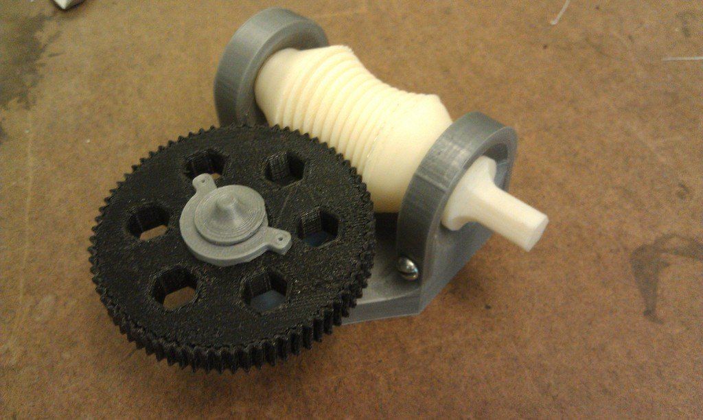
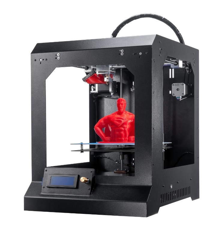
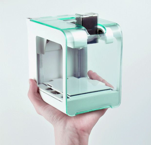
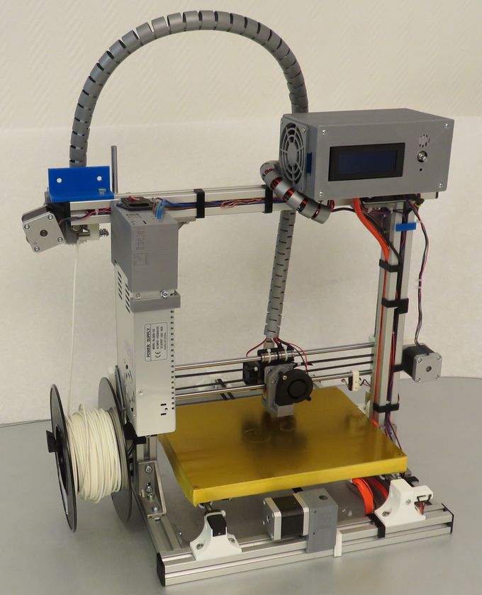
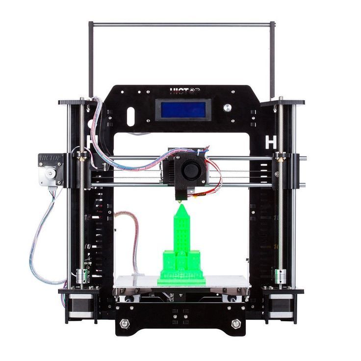
Which 3d printer is suitable for printing gears?
When we talk about printers, we mean FDM machines. These are 3D printers based on the layer-by-layer plastic deposition technology. Such devices allow you to close two tasks:
- Print broken parts. Plastic is not durable. A gear or other part may simply break or wear out.
- Printing custom or new parts. Development of spare parts from scratch. This also includes the design of gears for a homemade 3D printer.
It is difficult to name a specific printer model for making gears. It all depends on the size of the part and the corresponding working area of the machine. But one thing is for sure: the device must print with high accuracy. For such work, it is worth carrying out additional calibration of the desktop and extruder in order to avoid mass marriage during printing.
Important! The part design is usually downloaded as an STL file. Parts can be printed for personal use only, not for sale.
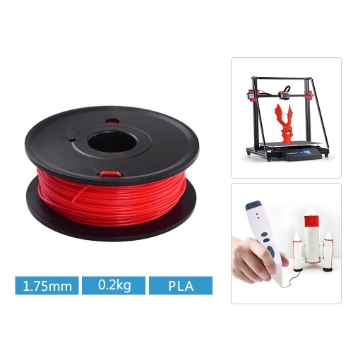
What materials are suitable for making a gear on a 3D printer?
Naturally, the main material is plastic. But it may differ, depending on the goals and the final strength of the finished product:
- Nylon (PA). Sufficiently durable material. This filament is considered one of the most reliable for the manufacture of moving parts and elements. A small minus of the material: it absorbs moisture well. You should not make gears out of nylon if the printer is in a room with high humidity.
- PETG. This type of plastic is also classified as high-strength. It is slightly inferior in characteristics to nylon. Printers appreciate it for its good sinterability of the layers, as well as for sticking to the work surface.
- PLA and ABS. These materials compete with each other. In terms of performance, they are approximately equal. Basically, the differences relate to the training of the printer himself. Some people are used to PLA and its operating temperatures of 75°C.
 Others have successfully used ABS by heating the material up to 105°C.
The choice of plastic depends on the skill of the printer, his financial situation, as well as on the final purpose of using the gear. If the part is lightly loaded and rarely used in work, you can choose PLA and ABS. For stronger parts, it is better to use PETG or Nylon (PA).
Interesting! PLA is known to be biodegradable. Because of this property, some printers are wary of using this type of plastic. They believe that the part can crumble over time. It's a delusion. The spare part may decompose if an appropriate environment is created for it. Nothing will happen to her in the air.
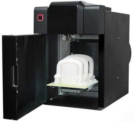
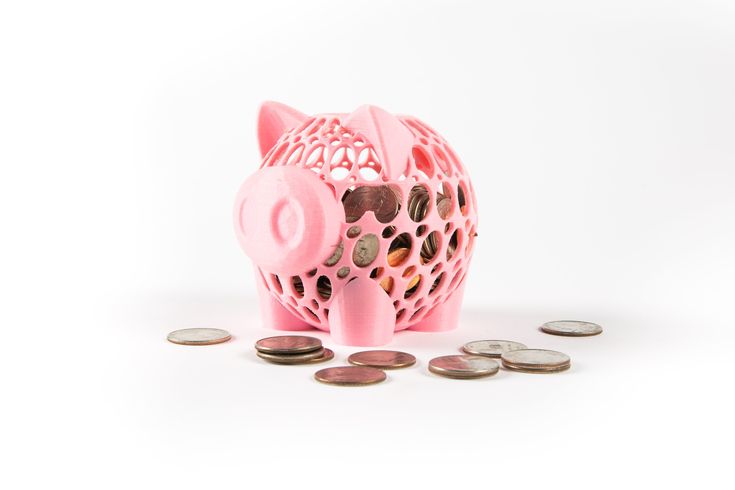
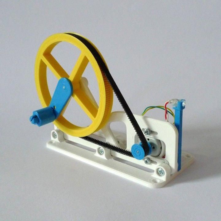
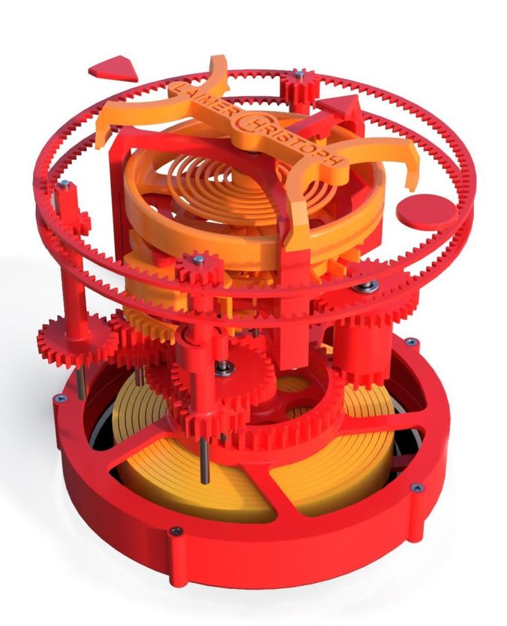
An example of finished products
How to print a gear on a 3d printer: step-by-step instructions
The entire printing process can be divided into three important stages: design (modeling), printing itself, post-processing of the finished product.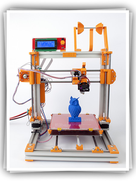 Consider the manufacture of a gear, starting with work in a slicer and ending with the final processing and lubrication of the part.
Modeling
The process of modeling is the basis. There are a few important things to keep in mind at this stage:
- If you have downloaded the industrial gear model in STL file, it is better to modify it manually. Namely, remove all cavities and holes that may be in the project. Such measures are allowed at the factory to reduce the cost of the part. At home, it is better to make a monolithic part. So stronger.
- For self-made parts, you need to calculate the optimal number of teeth, calculate the pressure angle. If your printer can print with high accuracy, without jambs, you can choose a larger gear ratio (number of links). This will affect the smoothness of the one-piece design where the gear will be installed. There are also rules for the pressure angle: for a part with a pressure angle of 20 degrees, the minimum number of teeth is at least 13 pieces; for a gear with a pressure angle of 25 degrees - the minimum number of teeth is at least 9things.
- Multi-tiered gears are best broken apart in a slicer and then glued together in post-processing. In this way, the best quality of the part can be achieved.
Be prepared for the fact that the part will have to be printed several times, along the way making adjustments to the 3D model of the product.
Slicing
Printing
The advantage of layering is that it is the cheapest way to get a part. Almost any gear can be made by yourself. But here also lie their disadvantages, which must be taken into account in the printing process itself:
- Material shrinkage. Each type of filament shrinks. You need to know it, otherwise the part will turn out to be out of size. Measure the percentage shrinkage on the test cube with a vernier caliper before printing. Add the result to the settings.
- The gear is a very precise item. Even a small deviation of 0.01 mm can affect further work. Therefore, it is important to calibrate the platen and extruder as perfectly as possible.
- Print defects. They must be removed before work begins. Print a test cube, preferably on 4 corners, to rule out any defects on the final product.
But printing is only half the battle. Without fail, the 3D maker is waiting for the post-processing procedure. And here, too, there are nuances.
3D printing defects
Interesting! Before printing, it is better to treat the desktop with ABS dissolved in acetone. Apply it in a thin layer. This will improve the adhesive properties of the surface. The first layer will not come off during the printing process.
Postprocessing
Perhaps one of the most important stages. It is impossible to rush here, as any oversight can lead to a defective product. Post-processing consists of several stages:
- Removal of supports, threads, sagging with a sharp knife or scalpel. Be careful, work without haste.
- Sanding with fine sandpaper.
 Removal and grinding of all irregularities, almost final processing.
 - Immerse the part in dichloroethane solution for 5-10 seconds. The liquid will penetrate into small cracks, glue and strengthen the part. This step is not necessary if you are working with a strong filament.
- End product lubrication. Last step. Lubrication is essential in heavily loaded systems. It prolongs the life of the part, the gears work more efficiently. For these purposes, it is better to take a thick lubricant based on: silicone, lithol or polytetrafluoroethylene. Apply the substance thickly with a dry paper towel so that no dust remains on the parts. Then forcibly turn the gear several times.
Be patient. In the post-processing process, the part may crack or even break. If this happens time after time, it may be necessary to change the filament and make adjustments to the design model.
Common causes of part failure in service: tooth wear to slip, tooth breakage due to excessive loading of the assembly, shaft fracture.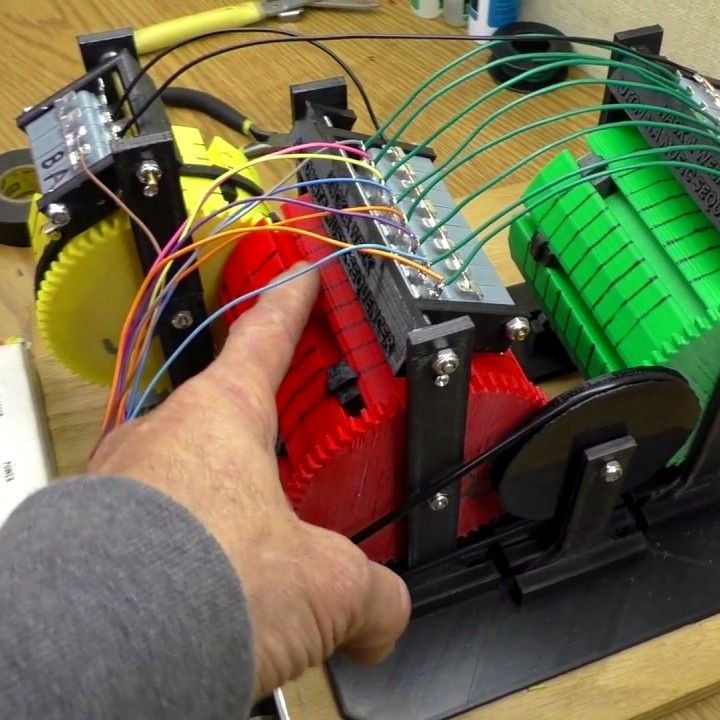 In rare cases, a hub or spoke breakage occurs.
Important! Do not use WD-40 on plastic parts. It's quite aggressive. It is designed to remove dirt from metal products, but not to lubricate plastic gears.
Post-processing part
Errors and how to avoid them
Of course, errors can occur during printing. And you need to notice them in time and be able to avoid them. We offer you to get acquainted with the list of the most common shortcomings that occur during the printing of gears:
- Reducing the diameter of the main hole of the gear. Often this is due to the fact that the user did not take into account the shrinkage of the material. Another reason is the export of the STL model with a low number of segments that form a polygonal gear hole. Always export a file with many segments. Otherwise, you will have to drill the hole manually.
- Gap between teeth. This issue can be encountered even with 100% infill enabled.
 The solution must be sought in the slicer by increasing the layer overlap parameter.
 - Low strength parts with thin walls. To make the teeth smoother, you need to set a smaller layer thickness. Straight infill printing with a minimum wall thickness of at least three perimeters.
- As mentioned above, it is better to make a solid part, without additional holes and recesses (not including the main hole in the center). You will not lose much on plastic, but the part will last longer than usual.
If a printer has never made gears on a 3D printer, then he will surely face one or more problems at once. And it is better to know about them "on the shore".
You will need a lot of patience and even more filament in the beginning.
Making gears at home is easy. The main thing is to take into account all the nuances and subtleties of the work in advance, develop an accurate model, and calculate the shrinkage of the material. You also need to be prepared for the appearance of errors or shortcomings.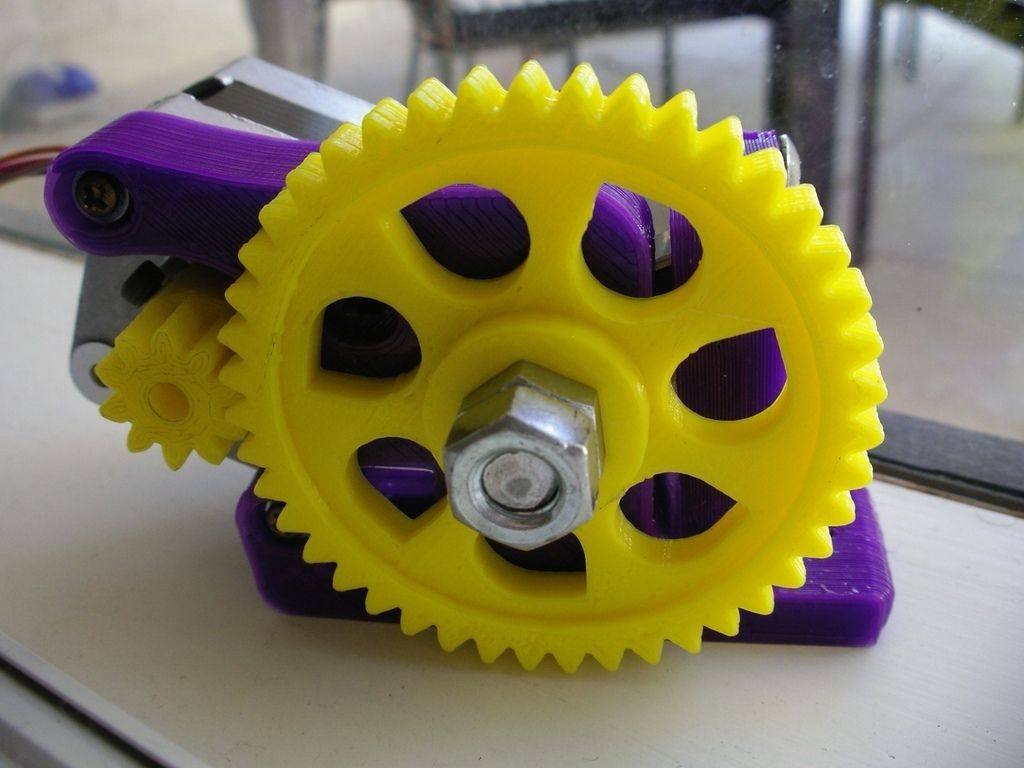 Some of them can be fixed in post-processing. Others - only by the method of complete alteration. But this is a workflow, nothing can be done about it.
- 07 March 2021
- 6452
Get expert advice
Set up and maintain FDM 3D printers for long life. Instruction for users.
Contents:
- Which 3D printer parts require regular maintenance?
- What is the maintenance of FDM 3D printers?
- Calibration and maintenance of the heating table.
- Cleaning and maintenance of the print unit.
- Cleaning and maintenance of 3D printer kinematics.
- Cleaning and maintenance of the hull.
- Electronics compartment, how to care?
- Output
Hello everyone, friends, 3DTool is with you!
Modern 3D printers have advanced systems for controlling the printing process, material supply, auto-calibration and many other useful, automated functions, and have gone quite far from their predecessors, where all manipulations, up to adjusting the current on the stepper motor drivers and programming the firmware for your version of the device, were necessary.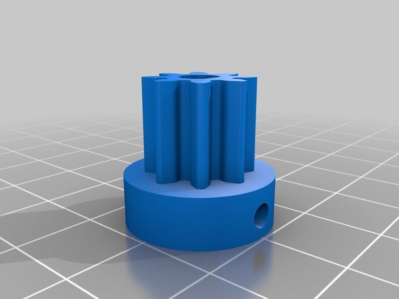 do it manually. However, most modern devices also require constant care and maintenance. Let's try to summarize the most necessary and common operations and describe them in our article as a kind of guide for new users.
Which parts of the 3D printer require regular maintenance?
To begin with, let's decide what large nodes can any 3D printer be divided into?
- Housing
- Kinematics
- Print unit
- Printing table
- Motherboard / electronics
Regardless of the 3D printing technology, any 3D printer can be broken down into these components. For example, the case requires cleaning from adhering dust outside or inside in order not to create a risk of a short circuit from static electricity, kinematics requires cleaning from adhering dirt, regular lubrication and, if necessary, replacing belts (not in the case of rigid kinematics on a ball screw), the printing unit must be cleaned of adhering material, and in the case of photopolymer printers, do not allow any contamination at all, especially if it is a DLP or SLA 3D printer.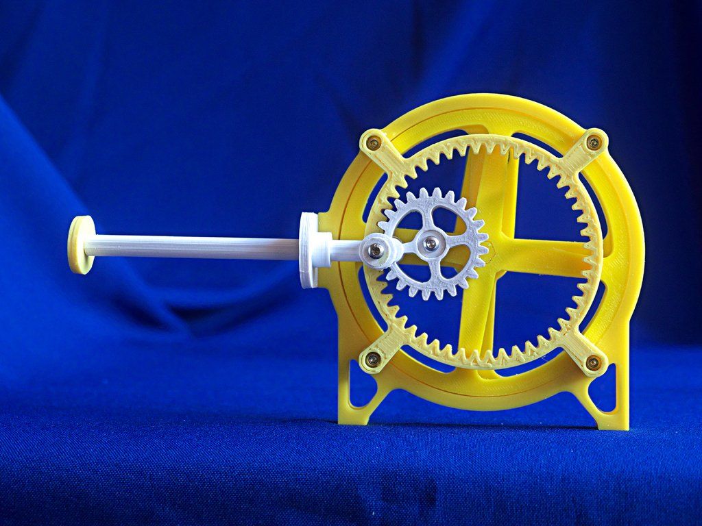
However, let's concretize our guide and take as a basis a certain standard FDM 3D printer, as the most common on the market, and based on it we will describe the processes in detail.
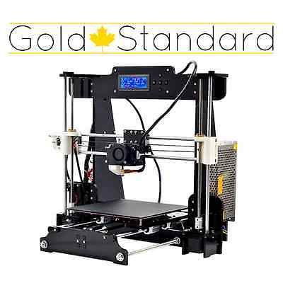
Catalog of FDM 3D printers
How to care for FDM 3D printers?
What the technology itself is and on what principle it works, you can find out from our article HERE. In this material, we mean that the reader is already familiar with the basic concepts and terms and understands the subject being described.
So. We know that thermopolymer 3D printers work with filament as a consumable, and the printing process itself is associated with heating the working elements of the device to fairly high temperatures. The molten material itself is deposited on the desktop either on a special adhesive surface (BuildTak), or on glass with glue applied to it, or on any other type of this element. For example, in the past, there were often just aluminum tables that required kapton tape or masking tape.
A good, even surface with adhesive applied is a 90% chance of a successfully completed print. The first layer always determines whether the product will turn out at all, or after a certain amount of printing time, if the first layer is peeled off or not printed, instead of the model you will see a characteristic "vermicelli".
Thus, the most important and first point of maintenance and adjustment of a 3D printer is the adjustment or calibration of the heating table.
Calibration and maintenance of the heating table.
There are 3 options for calibrating the heating tables - Manual, Semi-automatic and automatic. Most often in modern printers there is a semi-automatic option, we will now consider it.
With the semi-automatic option for calibrating the horizon of your work area, the printer runs a special motion program that facilitates the process. For example, in PICASO3D 3D printers on the X platform, the user needs to level the glass platform in its slots, start the calibration process and follow the device's on-screen instructions.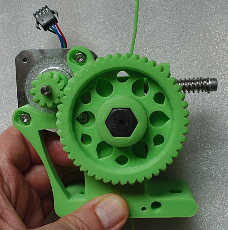 It is important to visually control the actions of the device and avoid strong distortions or gaps in the table and glass surface. This calibration should be done as often as artifacts appear on the first layer, or the filament does not stick to the table at all / is pressed into it too much.
In the case of manual calibration, for example, on Zenit 3D 3D printers, the printer also controls the process by moving the printing unit along the calibration points, but the operator himself must raise or lower the table at the corresponding point.
In the zenith 3D printers mentioned above, this allows you to make 3 special adjustment screws under the table console (pictured), which must be tightened until the distance from the table to the tip of the nozzle is +/- 100 microns. It is best to measure this distance with a special automotive probe (for adjusting valves), or using plain white A4 paper.
The essence of calibration is to adjust the height so that a sheet of paper or probe moves between the table and the nozzle with little effort, but still easily passes this gap. It will be necessary to do this in the case of a zenith at 3 points, however, as a rule, in such devices, calibration is performed at 4 points.
!Note!
When applying adhesive varnish/spray to the glass tabletop, always calibrate _after_ application, otherwise the level may “escape” during the glass change. For the best adhesion to printers with a glass table, we can recommend the adhesive adhesive proven over the years - Picaso3D Spray.
The next node that requires frequent attention and care is the printing block. Let's talk about it next.
Cleaning and maintenance of the print unit.
The design of this assembly is such that the lowest point, the tip of the nozzle, is always in contact with the material. On many configurations of its shape, the lower edge, as it were, "smoothes" the layer of material emerging from it. In view of this, it is almost impossible to avoid plastic sticking to the surface of the nozzle, which over time will lead to its contamination, because the nozzle goes through heating / cooling cycles and the adhered plastic caramelizes, forming a kind of "plaque".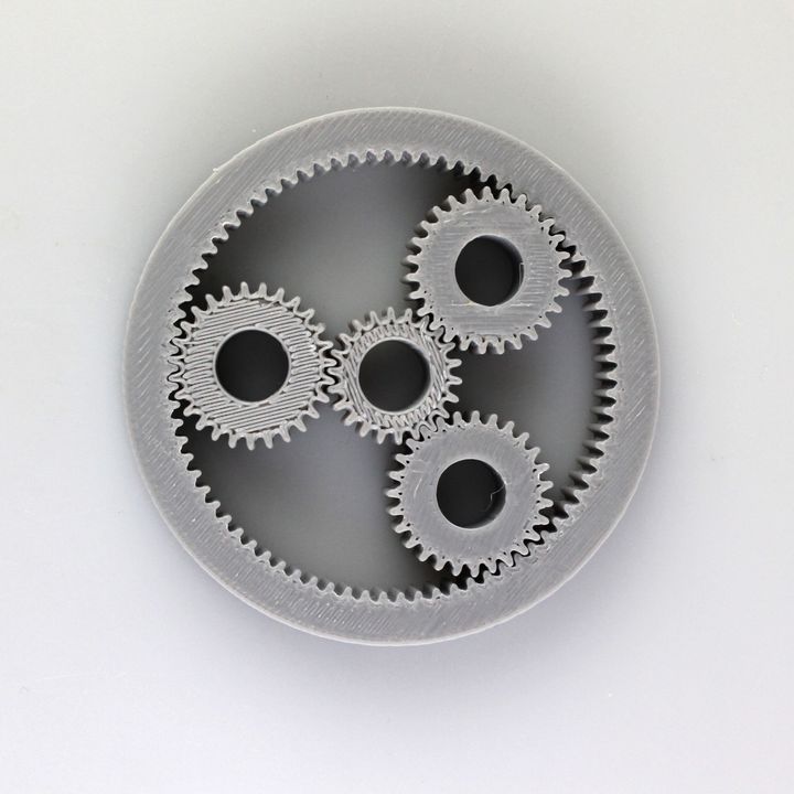 Also, in case of rare, but inevitable printing defects, or an incorrectly calculated job, large amounts of material can stick to the nozzle, which eventually gets onto the surface of the product during the next prints and spoils it.
To ensure that the nozzle is always clean, after every two or three successful prints, try to wipe the nozzle with non-woven wipes, or a flame-retardant cloth at a time when the nozzle is still hot.
If this is not possible, or the contamination is too great, there is a more radical method that requires removing the nozzle.
There are quite a few ways to clean the removed nozzle and there is no need to describe them all in this material. It is enough to list two main ones: dissolving plastic in a solvent, or burning it with a gas burner.
!ATTENTION!
Any method indicated below requires you to have a prepared room with an exhaust hood and equipped with a fire system. In no case do not carry out these procedures at home.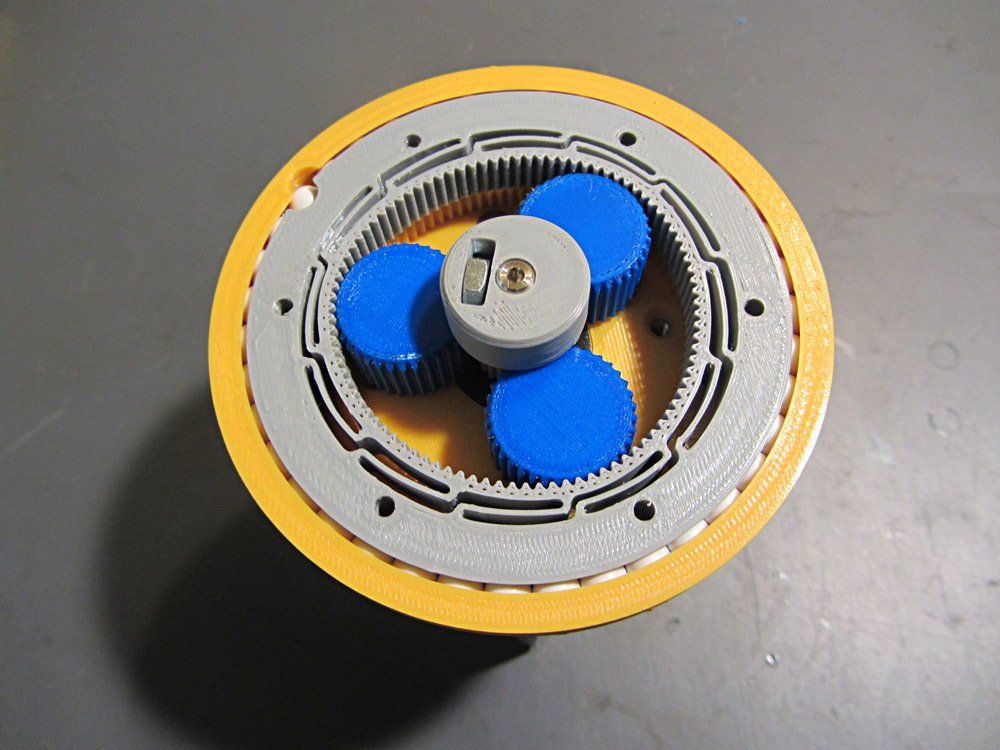 It may be dangerous!
In the first case, the nozzle is lowered into acetone and kept in it for several hours, after which the remaining plastic is manually cleaned off with a stiff brush.
In the second case, you need a gas burner and long thick tweezers / tongs with which you will hold the nozzle. It is necessary to heat it to a slightly reddish state so that all the plastic burns out and cool in warm water. After that, it can be installed back into the printer after drying.
Catalog of FDM 3D printers
Cleaning and maintenance of 3D printer kinematics
The kinematic system of your 3D printer is the most important node that provides most of the print quality of the device. The execution of kinematics, the quality of its units and conditions affect the product no less than the filament itself or the printing unit. Of course, one cannot work without the other, but if you encounter "artifacts" that suddenly appear on the surface of your printouts and are sure that this is not the fault of the print unit or electronics, pay attention to your kinematics.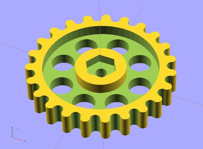
Different 3D printers are built on different kinematic schemes. They use belts of different lengths, different types of guides and brackets, different types of bearings and spools. However, they have one important thing in common - all of them require cleanliness and timely lubrication. How to lubricate one or another type of guides and their carriages, as a rule, can most often be found in the printer manual, and the procedure itself must be performed when the printer is heavily loaded at least once a month. In addition, the more often the device works, the slower the lubricant becomes unusable, and the more the device is “idle”, the more likely it is that the guides are clogged with dust and the lubricant has lost its properties.
To reapply it, unplug the printer from the mains and manually move the print unit, successively clean the guides from old grease and adhering dirt with a rag or non-woven cloth soaked in gasoline / alcohol. Then wipe dry and apply a little lubricant evenly along the entire length of the guides.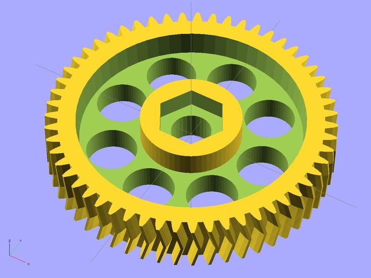
Note that rail guides most often have breathers to inject grease into the body of the bottom bracket, and cylindrical bearings get clogged with grease inside. Of course, it will be best to change the lubricant on the elements with a complete analysis of the kinematics, but for inexperienced users we will not advise this. Just contact the nearest service and trust the professionals.
Catalog of FDM 3D printers
Cleaning and maintenance of the hull.
Depending on the material that the body of your 3D printer is made of, you can choose different cleaning scenarios. For example, if the case is made of dibond, as in PICASO 3D printers, it is enough to use a furniture cleaner and an ordinary antistatic spray. The same should be done with elements made of acrylic / plexiglass.
If your case is plastic or metal, before cleaning you need to make sure that the products you use will not damage the paint and / or plastic, this can be checked by the markings on the bottles of such products.
Why do you need to clean the case at all? A rare reader will ask. And we will answer: for the simple reason that even grounded 3D printers with numerous protection against static and filters on the power cord are not immune from the discharge of accumulated energy through the motherboard or other electronic components, which can disable them. In addition, a dirty case inside and out is simply dangerous from the point of view of spontaneous combustion and not aesthetically pleasing.
And yet, what about electronics?
Electronics compartment, how to maintain?
Through numerous slots in the case and ventilation holes, dust and other debris can enter the electronics compartment. As you might guess, electronics are the brains and nervous system of your device. Without it, your 3D printer is nothing more than a bunch of gears and plastic. By itself, the electronic filling of the device is usually protected from various misfortunes with the help of grounding, various filters, meshes and active blowing, but over time it is still covered with a layer of fine dust or dirt and requires periodic attention.
If your device's electronics bay is difficult to access and requires the floor of the printer to be disassembled for inspection/cleaning, we do not recommend this. If the case requires unscrewing one / two covers, regularly check the condition of the system and, if necessary, blow it with compressed air. But never vacuum! Ordinary household vacuum cleaners can be compared to huge magnets that accumulate static on their bodies, with direct contact with which a spark can run through your electronic components and boards in an unplanned scenario and simply damage them.
The best way to clean the dust compartment is to manually clean the fan blades and blow out the components with compressed air. In this case, it is desirable to do the whole process under a good hood or in the open air.
Conclusion.
Like any other complex technical device, a 3D printer requires regular care and maintenance. It may include both periodic full inspections, analysis with the elimination of minor problems, as well as simple cleaning of rubbing / heating elements and caring for the appearance of the device.