3D printer gear cube
▷ gear cube 3d models 【 STLFinder 】
Gear Cube
grabcad
A working model of gear cube (teeth are imperfect though)
Gear cube
prusaprinters
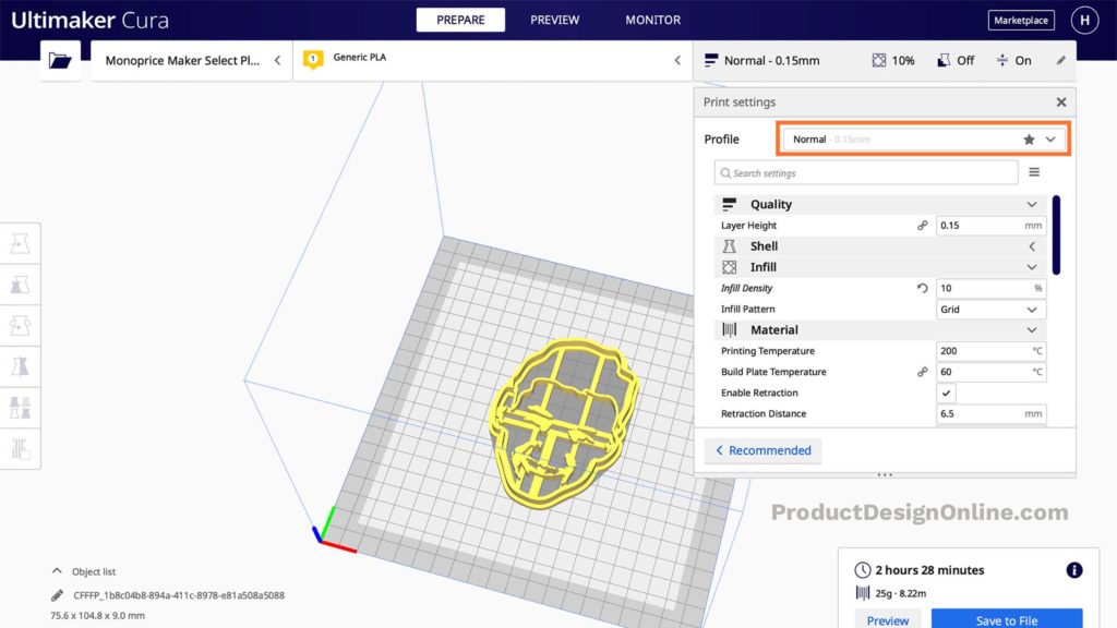
Sometimes designs like this are called “brain gears”.To make this, you will need two copies of the half core, eight copies of the gear and its cap, twelve M2 nuts, four 16mm M2 bolts and eight 12mm M2 bolts.First, use four of the nuts and the 16mm...
Gear Cube
grabcad
A set of conical gear parts that interlock to a central hub part to form a cube you can twist. My sister brought me home one of these 3d printed from some dork at MIT, and here is my shot at modeling it. This model uses A LOT of in-context...
Gear Cube Globus Holder
thingiverse
can be used for emmetts gear cube or other things, like rubik's cubes
Gear Cube Stand
thingiverse
This is a stand for emmetts gear cube. ... If you scaled your cube up or down, just scale this stand accordingly and it should fit.
Gear Cube Stand
thingiverse
Just a simple stand for the gear cube that takes about 1 hour to print scale it up to 101-103% Tried to keep it as simple as possible
Gear Cube Stand
thingiverse
something to display the Gear Cube for you desk or whatever.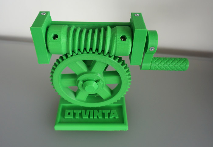 ...Print Settings Printer Brand: Prusa Printer: Prusa...
Motorised Celtic Gear Cube
thingiverse
A fun little motorised version of the beautiful Celtic gear cube. https://youtu.be/1_8n0StP3D8 Motor is a "N20 DC gear motor", battery a CR2032. Original intention was to add electronics to have it rotate exactly one revolution every once in a...
Alex Kim Gear Cube
thingiverse
... with Customizer! ...http://www.thingiverse.com/apps/customizer/run?thing_id=213946 Instructions Using the following options: type = 0 Font = write/Letters.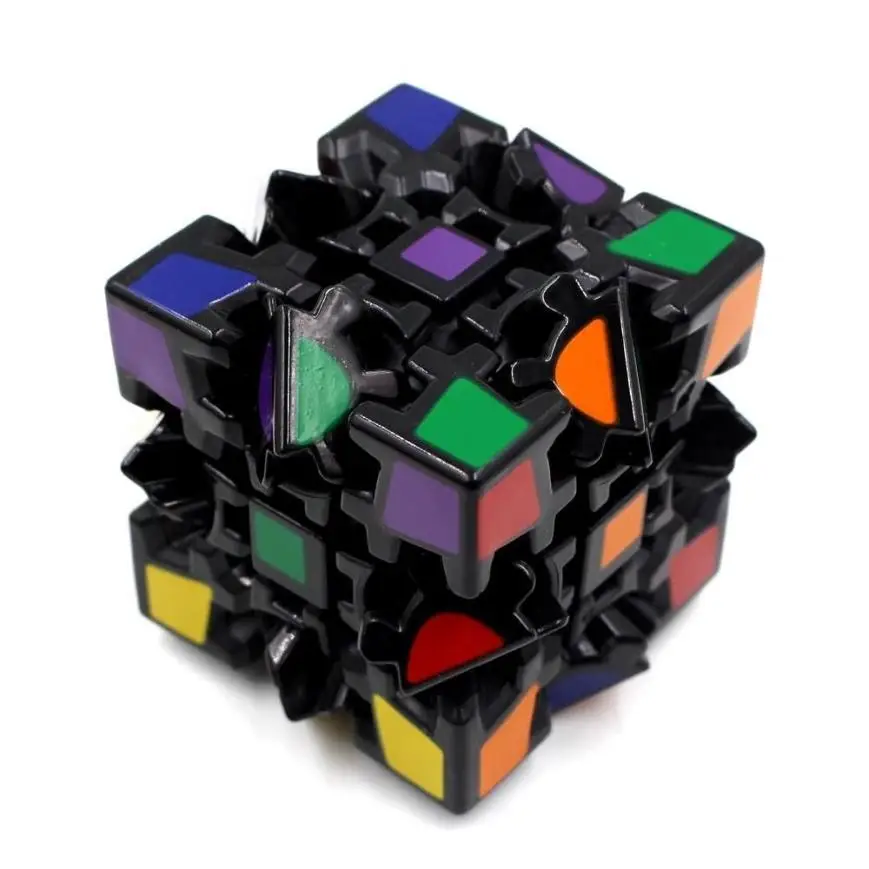 dxf object = 4 Backlash = 0.5 word3 = Gear Cube word2 = Alex Kim word1 = Makerbot fontsize = 4.5
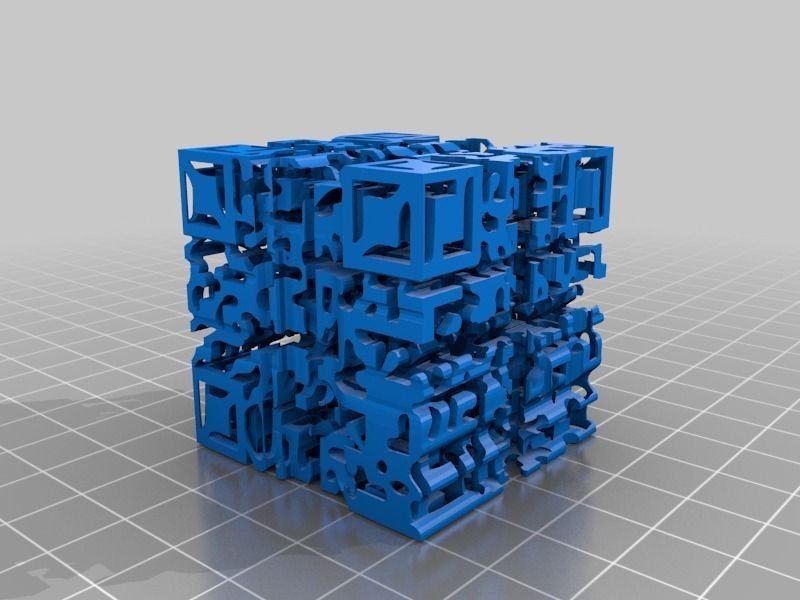
Celtic gear cube
thingiverse
After printing a bunch of simple gear cubes I decided to make something special. Yesterday I found a box with celtic ornament and combined this pattern with gears. Print time was about 14 hours with 50mm/s movements, 20% infill, 3 walls. Central...
Gear Cube
thingiverse
Customized version of http://www.thingiverse.com/thing:213946 Created with Customizer! ...http://www.thingiverse.com/apps/customizer/run?thing_id=213946
gear cube
thingiverse
Customized version of https://www. thingiverse.com/thing:1672381
Created with Customizer! ...https://www.thingiverse.com/apps/customizer/run?thing_id=1672381
thingiverse.com/thing:1672381
Created with Customizer! ...https://www.thingiverse.com/apps/customizer/run?thing_id=1672381
gear cube
thingiverse
Customized version of https://www.thingiverse.com/thing:1672381 Created with Customizer! ...https://www.thingiverse.com/apps/customizer/run?thing_id=1672381
Gear Cube
thingiverse
Customized version of http://www.thingiverse.com/thing:213946 Created with Customizer! ...http://www.thingiverse.com/apps/customizer/run?thing_id=213946
Longer Peg For Gear Cube
thingiverse
This is a remix of http://www. thingiverse.com/thing:213946 I found the gear cube to be very tight and hard to turn. I have extended the pegs by 1mm. This leaves more room between the gears and makes them much easier to turn. This is the peg only,...
gear cube toy
cults3d
This is a cube whose 4 gears rotate simultaneously
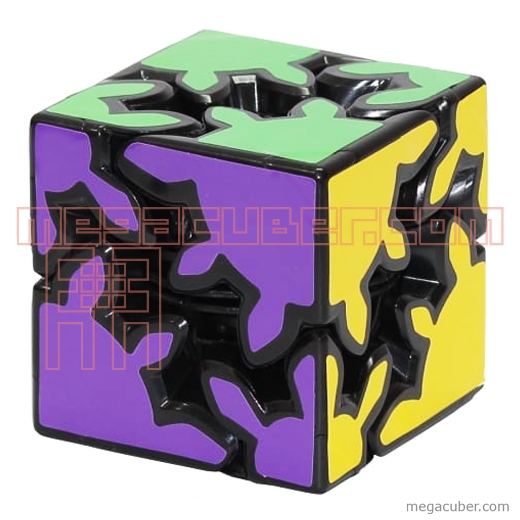
Gear cube rubik
cults3d
66x66x66 mm cube with entertaining and ingenious swivel gears. 66x66x66 mm hub with entertaining and ingenious rotating gears. ... Average of 66x66x66 mm with various and ingénieux rotating gears.
Sweet awesome gear cube
thingiverse
Customized version of http://www. thingiverse.com/thing:213946
Created with Customizer! ...http://www.thingiverse.com/apps/customizer/run?thing_id=213946
Print: 4 Small Gears, 4 Large Gears, 8 Clips and one center piece.
...
Enjoy.
thingiverse.com/thing:213946
Created with Customizer! ...http://www.thingiverse.com/apps/customizer/run?thing_id=213946
Print: 4 Small Gears, 4 Large Gears, 8 Clips and one center piece.
...
Enjoy.
LED (tea light) Stand for Gear cube.
thingiverse
A stand which can house a tea light to illuminate the gear cube or indeed any 50mm square base.
Twisted Stand for Emmett's Gear Cube
thingiverse
Simple stand for the gear cube. See http://www.thingiverse.com/thing:213946 Instructions I print with 0%fill, 2 shells and 0. 25mm layer height. ...Comes out best using translucent filaments.
Screwless gear cube/heart pin tool
thingiverse
Inserting the pins into the center hub of the screwless gear cube and heart were kind of a pain in the fingers. This tool makes assembly much easier. Instructions Use the end marked long for the...
Gear Cube - Fidget (100% printable)
prusaprinters
The small & big version are 100% printablealternative: 4x 608ZZ ball bearings (8mm x 22mm x 7mm) for the BigVersionNeeded To Print:4x Gear4x screw1x CenterCubePrintsettings [Screw]:Infill 50%Layerhight: < 0. 1mm3 WallsXY size...
Display handle for Gear Cube
thingiverse
I have printed it and tested it and know if works PERFECTLY (I am just too lazy to deal with pictures :) ) The tip has been extended so it grabs the cube properly and is firm so if someone picks it up, nothing is going to fly. I also changed the...
Gear Cube Part: Center
thingiverse
Customized version of https://www.thingiverse.com/thing:213946 Created with Customizer! ...https://www.thingiverse.com/apps/customizer/run?thing_id=213946
SFUN Gear Cube
thingiverse
Customized version of http://www. thingiverse.com/thing:213946 Created with Customizer! ...http://www.thingiverse.com/apps/customizer/run?thing_id=213946 Instructions Using the following options: word3 =...
Sungevity Gear Cube
thingiverse
Customized version of http://www.thingiverse.com/thing:213946 Created with Customizer! ...http://www.thingiverse.com/apps/customizer/run?thing_id=213946 Instructions Using the following options: word3 =...
ROSCO Gear Cube
thingiverse
Customized version of http://www.thingiverse.com/thing:213946 Created with Customizer! . ..http://www.thingiverse.com/apps/customizer/run?thing_id=213946 Instructions Using the following options:...
Disco gear cube parts
thingiverse
part of a project for a class,
Gear Cube Part: Pin
thingiverse
Customized version of https://www.thingiverse.com/thing:213946 Created with Customizer! ...https://www.thingiverse.com/apps/customizer/run?thing_id=213946
Gear Cube Standard
thingiverse
Customized version of http://www. thingiverse.com/thing:213946 Created with Customizer! ...http://www.thingiverse.com/apps/customizer/run?thing_id=213946 Instructions Using the following options: word3 =...
Fidget Gear Cube 3D Printed
Etsy is no longer supporting older versions of your web browser in order to ensure that user data remains secure. Please update to the latest version.
Take full advantage of our site features by enabling JavaScript.
Click to zoom
Price: €8.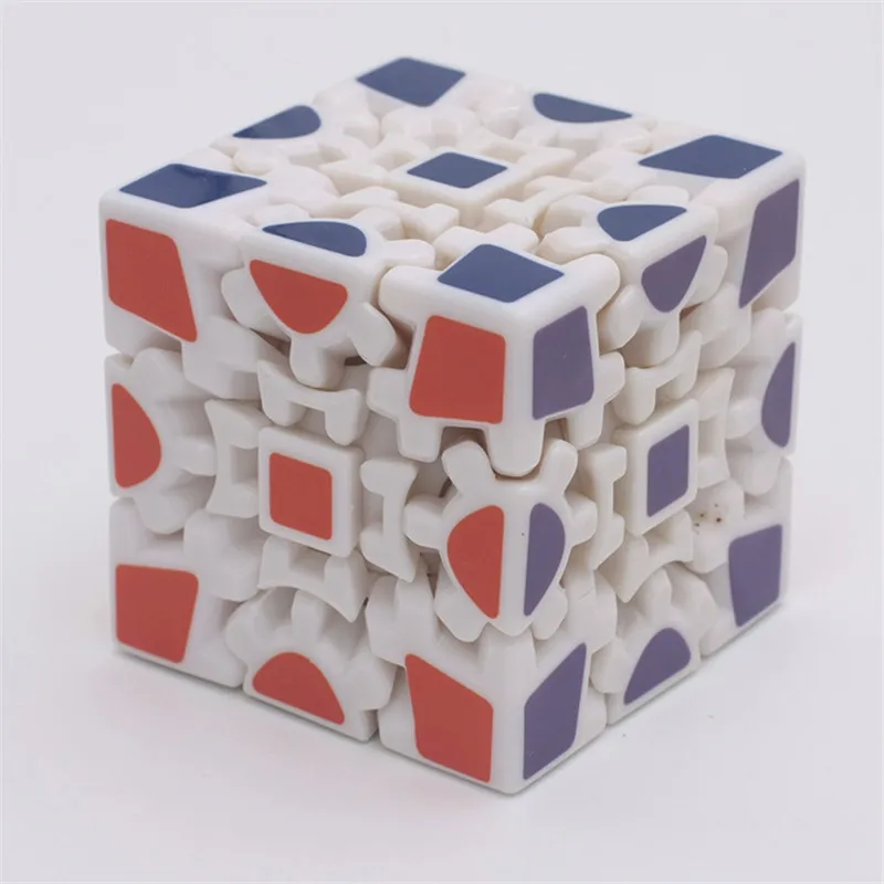 48
48
Loading
VAT included (where applicable), plus shipping
4.5 out of 5 starsby AJC3D
Primary color
Select a color Beige Black Blue Brown Clear Green Orange Pink Purple Red Silver White Yellow
Please select a color
Secondary color
Select an option Beige Black Blue Brown Clear Green Orange Pink Purple Red Silver White Yellow
Please select an option
Quantity
12345678910111213141516171819202122
Explore more related searches
- Geared
Listed on Mar 1, 2023
108 favorites
Report this item to Etsy
Choose a reason…There’s a problem with my orderIt uses my intellectual property without permissionI don’t think it meets Etsy’s policiesChoose a reason…
The first thing you should do is contact the seller directly.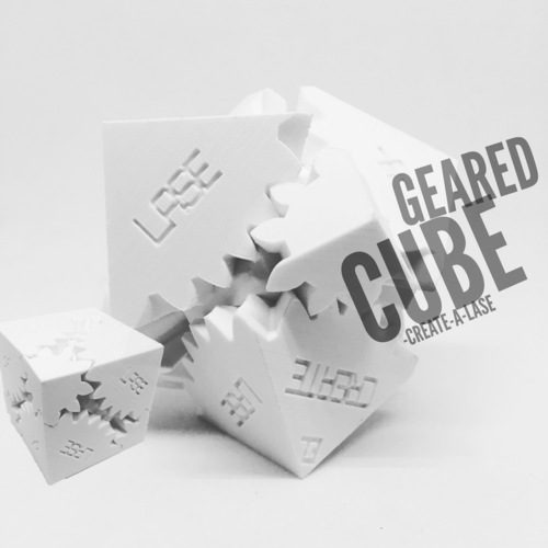
If you’ve already done that, your item hasn’t arrived, or it’s not as described, you can report that to Etsy by opening a case.
Report a problem with an order
We take intellectual property concerns very seriously, but many of these problems can be resolved directly by the parties involved. We suggest contacting the seller directly to respectfully share your concerns.
If you’d like to file an allegation of infringement, you’ll need to follow the process described in our Copyright and Intellectual Property Policy.
Review how we define handmade, vintage and supplies
See a list of prohibited items and materials
Read our mature content policy
The item for sale is…not handmade
not vintage (20+ years)
not craft supplies
prohibited or that use prohibited materials
not properly labeled as mature content
Please choose a reason
Tell us more about how this item violates our policies.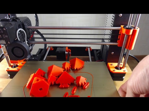 Tell us more about how this item violates our policies.
Portfolio
- Model Lakhta Center
01
Model Lakhta Center.
Model height 16cm.
3D printing
Material: PLA
Cost: 1800r
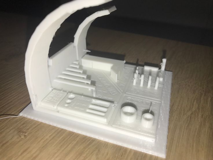
- City apartment constructor
01
City apartment layout designer.
- Material: PLA
- Print thickness: 0.1mm
- File: http://www.thingiverse.com/thing:943662
- Rubber handle
01
Rubber control handle.
(Copy from the original)
Height: 16cm.
Manufacturing: 3D printing
Material: Flex (TPU)
Cost: 1500r
- Lego parts
01
A rare piece for Lego, made according to the customer's request.
- tracer
Tracer figure from Overwatch.
Height: 43cm.
Production: 3D printing + painting
Material: HIPS
Cost: 15000r
- Skull - training stand
01
Training stand for medical workers.

- Differential layout
02
Teaching model to understand the differential
- Steering wheel for flight simulator
01
Housing for flight simulator helm
- Action Figure Hotei Stormtrooper
01
Figurine. ABS plastic.
- Equipment for the production of lamps
02
Tool for marking the radiator hole for the LED luminaire.
Production: 3D printing
Material: PET-G
Cost: 500 rub
- Plates on the door
02
Various signs on the door
Production: 3D printing
Material: PLA
Cost: 250 rubles/pc.
- Handle pads
02
Linings made according to the customer's 3D model.
Fabrication: 3D printing
Material: PET-G
Cost: 522 rubles/pc.
- Mounting the echo sounder on an ATV
A part for attaching the echo sounder was made.
Scanning / reverse engineering of a standard part (mirror) - 40000 rub.
Production: 3D printing
Material: PET-G
Weight: ~2500g
Cost: 25000r
- Housing REA
REA building.
Production: 3D printing
Material: PET-G
Cost: 2500r
- Replacing old gears
01
Created new gears from the original worn ones.
Production: 3D printing
Material: PET-G
Cost: 1000r
- companion cube
02
Box in the form of a Companion Cube from the game Portal2.
Production: 3D printing
Material: PET-G Cost: 3000r
- shovel handle
The handle of your favorite shovel has been restored.
Fabrication: 3D printing
Material: TPU
Cost: 1500r
- Enclosure for RapsberryPI
Housing for the popular RapsberryPI 4 board.
Fabrication: 3D printing
Material: PET-G
Cost: 850 rub.
- Pot/planter for plants
01
Pot/planter for indoor plants with parametric shape.
 An excellent solution for the interior.
 Model height 17cm.
Production: 3D printing
Material: PET-G
Cost: 1500r
- Enclosure for Arduino Mega
01
Plastic case for Arduino Mega 2560 board with holes for all pins.
Production: 3D printing
Material: PET-G/ABS/ABS V0
Cost: 800r
- Speaker box
02
Electronics housing with speaker output.
Manufacture: Casting in a silicone mold
Material: Reaktoplast
Cost: 2000 rub/piece
- Control panel housing
02
Part of the housing for the control panel.
Manufacture: Casting in a silicone mold
Material: Reactoplast
Cost: 800 rub/piece
- Plastic gear
01
Made of plastic instead of the old one, on which the teeth were licked off.
Production: 3D printing
Material: PET-G
Cost: 1000r
- A spare part for a tape recorder.
01
Manufactured a spare part for a tape recorder.
Production: 3D printing
Material: PET-G+FLEX
Cost: 2000r
- Gear restored
01
Restoration of the gear according to the original part.
- Polyurethane gaskets
01
Gaskets. Material PU
- Speedometer housing
01
Speedometer housing for painting.
- Rubber gaskets
01
Polyurethane gaskets.
- BMW rim cap
We created a 3D model and printed it on a 3D printer. Cap for a disk of the BMW car.
- Fastening
01
Refurbished mount. Service: Modeling + 3D printing.
- Plug housing
Plug housing for watertight wire connection.
We created a 3D model according to the drawings and printed a functional part on a 3D printer.
- Prototype wheel for balance bike
Prototype balance bike wheel.
Material: PLA (orange)
Print thickness: 0.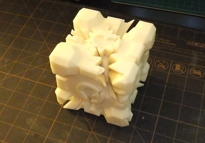 2mm
2mm - Shimano PD-M647 pedal frame
Replacement frames for Shimano PD-M647 pedals
Material: PLA (Green)
Print thickness: 0.2mm - Propeller prototype
Order: printing of a prototype propeller with detachable blades.
Material: PLA
Layer thickness: 0.1mm
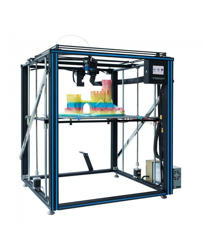
Instructions for setting up all the mechanics of a 3D printer: from belts to speeds
The quality of the printed models directly depends on the mechanics of the printer, namely on its correct settings. Any elements of the printer wear out over time, so the printer must be set up at least once every 5-6 kg of printed filament. With the help of the short instructions described in this guide, you can quickly and easily set up the mechanics of your printer: belt tension, motor current, motor steps, acceleration, jerk and speed.
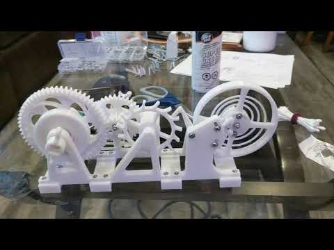
Mechanics includes
3D printers of any design always contain the same things: Axes and rails along which the elements of the printer move and motors with belts that set these elements in motion.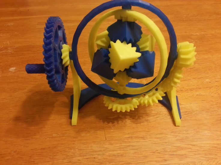 In a classic printer design, there are at least 3 motors (one for each axis), 3 rails (one for each axis) and an electronics board that controls the motors. The latter can hardly be called part of the mechanics, but since it controls the engines, it also indirectly affects the quality of the model.
Printing defects due to mechanical problems
Before changing anything in the printer, you need to decide what exactly needs to be configured. Often defects are visible visually. Our blog has an article about most printing defects, which details the reasons for their occurrence. The following is a list of defects and what element of mechanics they are associated with:
-
Layer shifting - Belts, Motor current, Guides
-
Ringing - Guides, Speed
-
Incorrect model geometry - Guides, Motor steps, belts
As you can see, all the above problems do not interfere with the printing process itself, but the result leaves much to be desired. Sometimes mechanical errors can completely stop the printer from working. Therefore, it is better not to take the situation to extremes and, if any problems arise, immediately start checking and configuring the 3D printer.
How to save settings
To fix some defects, you need to change the printer software settings. Therefore, before adjusting the mechanics, it is necessary to understand how to properly store the settings inside the printer. There are 3 ways to do this:
All settings are located in the corresponding menu of the printer
Depending on your firmware, this manual will indicate code sections for MARLIN firmware in the configuration.h file
We first enter the parameters into the printer and then store them in EEPROM - the internal memory of the microcontroller. Or paste all the necessary settings at the beginning of GCODE. To learn how to do this, read our article on working with GCODE and creating macros.
To save to EEPROM, you need to send the printer a command to change some value (which can also be inserted into the initial GCODE), and then send the M500 command (save the current settings to permanent memory).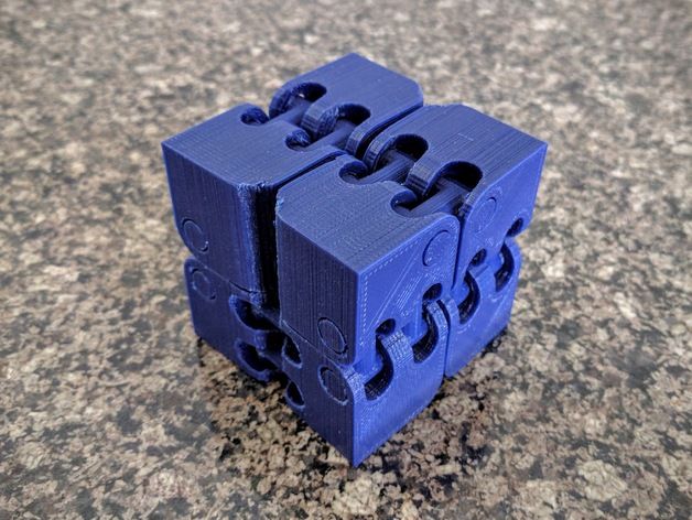 The EEPROM function must be enabled in the firmware, for this you need to remove two slashes in the line:
//#define EEPROM_SETTINGS
Whichever option you choose, you should be careful when using any commands. You will not be able to harm the printer in any way when changing the settings, but if you make a mistake, you will have to look for the cause of possible further problems for a long time.
Setting Instructions
Now you can start setting up the printer itself. If you decide to set several parameters at once, then it is better to use the order of adjustments as in the article, since some of the settings are related to each other and if you use the wrong order, adjusting one element of the mechanics will override the settings of another element. For example, you should not adjust the motor steps before tightening the belts, as changing the length of the belts will change the "true" steps per millimeter of the motors. Also, before setting up, you must make sure that there are no backlashes in the printer frame, tighten all belts.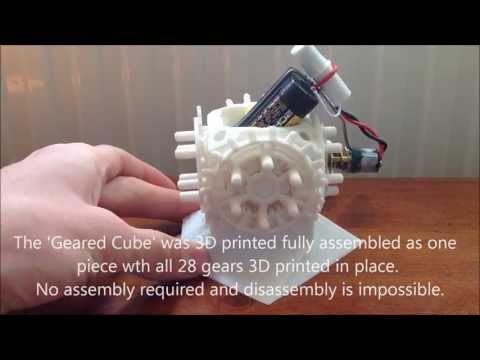
Belts
The first thing to start setting up the printer is the belts. They directly affect the geometry of the model and, when pulled too much, they cause a lot of problems: displacement of layers, changes in geometry, ripples. First you need to make sure the belt is intact. To do this, look at the entire belt, especially the areas where the belts bend. If the belt has outlived its usefulness, then you can see a section of the belt where the distance between the teeth has greatly increased and a metal wire (cord) is visible between them. This means that it's time to completely change the belt.
Broken belt with broken cords
If the belt is intact or you have already replaced it, then you can proceed to the next step. Depending on the design of your printer, you need to move the roller through which the belt passes. The tension should be such that the carriage or table moves effortlessly, but at the same time, when moving quickly, the belt should not slip the teeth on the motor gear.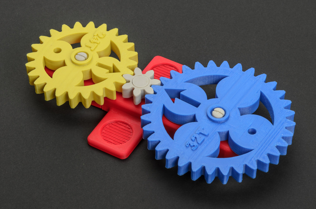 Adjust the tension of the belts on each axis of the printer using this method.
Tip: if your printer came with a belt tensioner in the form of a spring attached to the belt itself, remove it. Due to the flexibility of this tensioner, printing defects will occur, such as protruding corners on the model. It is better to adjust the belt without using this tensioner.
Belt tensioner
Current motors
As we know from the school physics course, the power of the engine depends on the voltage and current strength. Since the voltage on all printer electronics is the same everywhere, the only thing that can be changed is the current on the motor. More precisely, it should be said the maximum current that the driver will supply to the motors. To change this limit, you need to climb inside the case and find the printer board. On it you will see the printer driver. We are interested in a small potentiometer on the driver itself (in the picture below it is indicated as a tuning resistor).
Example of potentiometer location on driver
For adjustment, you will need a voltmeter and a small Phillips or flathead screwdriver. Before proceeding further, it is necessary to calculate the maximum current supplied to the motors. Different formulas are used for different drivers, the most popular ones will be listed in the table below:
| Driver name | Formula | Explanations |
| A4988 | Vref = Imax * 1.25 for R100 | To understand which formula to use, you need to find a resistor with the signature R100 or R050 on the driver. They are located next to the driver chip. |
| DRV8825 | Vref = Imax / 2 | |
| LV8729 | Vref = Imax / 2 | |
| TMC2208 TMC2100 TMC2130 | Vref = Imax * 1. | One formula for all drivers |
 41
41 The value of the maximum current (Imax) depends on the motor controlled by the driver. This can be found in the engine specification or on the sticker on it. The following are the currents for the most popular motor models:
17HS4401 - current 1.7 A
17HS8401 - current 1.8 A
17HS4402 - current 1.3 A
Substituting the value into the formula, we get the Vref value for the maximum current supplied to the motor. But at this value, the engine will get very hot, so the resulting Vref value must be multiplied by 0.7. For example, for a motor with a maximum current of 1.5 A and a TMC 2208 driver:
Vref=1.5*1.41*0.7=1.48V
Now the resulting value can be used when configuring on the printer itself. To do this, disconnect the wires going to the motors, turn on the printer and place one voltmeter probe in the center of the trimmer, and the second probe to the negative terminal on the power supply (you can also use the negative terminal on the printer board and the contact on the driver, labeled as GND). You will see some value on the voltmeter screen. Turn the trimmer clockwise to decrease the Vref value and counterclockwise to increase it.
Attention: you should not specify a Vref value higher than the maximum calculated for your engine! Otherwise, the engine will soon break down!
Once you have adjusted the value on the drivers, you can turn off the power to the printer, connect the motor wires, and put the case back together. This completes the driver setup.
Motor steps
When setting up motor steps, you will need a ruler. For convenience, you can use the program Repetier-Host. The adjustment for each of the three axes occurs according to the same algorithm:
-
Set the caret to zero coordinates (Autohome or G28)
-
Move the carriage some distance
-
We measure how far the carriage has traveled
-
We calculate the correct number of steps per millimeter using the formula:
True steps per millimeter = current steps per millimeter * reported distance / distance traveled
For example, if the printer was set to 100 steps/mm, we tell the printer to move 80mm and the printer travels 87. 5mm. Then the correct steps per millimeter would be 100 * 80 / 87.5 = 91.42 steps/mm. For the convenience of measurements, you can fix a ruler on the table, and a thin object, such as a needle or pin, on the carriage. Then it will be possible to accurately measure the distance traveled. The extruder uses a partially different algorithm to measure distance:
-
Inserting plastic into the extruder
-
Cut it right at the outlet
-
We give the printer a command to stretch the plastic a certain distance (at least 100 millimeters)
-
Cutting plastic again
-
We measure the length of the resulting piece of plastic
-
We use the formula from the previous algorithm
Next, the settings data must be inserted into the firmware in the line:
#define DEFAULT_AXIS_STEPS_PER_UNIT {X,Y,Z,E0}
X,Y,Z and E0 should be replaced by the steps per millimeter for each of the axes, respectively.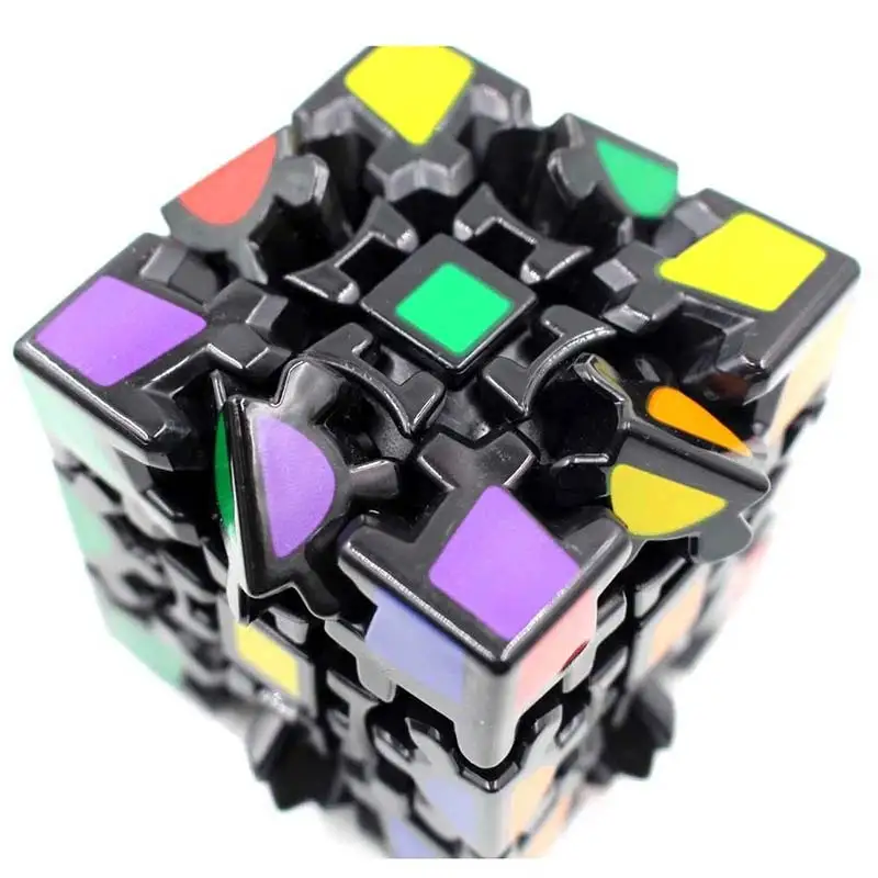 Otherwise, you need to insert this line into the initial GCODE:
M92 Ennn Xnnn Ynnn Znnn
Instead of nnn in each of the parameters, you must substitute the steps per millimeter for each axis. If you want to adjust the steps only for not all axes, then you can remove unnecessary parameters.
Acceleration
This parameter is responsible for the rate of change of speed. That is, how fast the printer will change its speed. This affects the nature of the movement of the hot end relative to the table. If the acceleration is too small, then the printer will print slowly, if it is too large, then the outer surface of the model will have visual defects: fading waves will be visible near each of the corners, as in the picture below.
To set up acceleration, you need to follow simple steps:
-
Cut a model of a standard test cube with a wall thickness equal to one nozzle diameter, without filling and top layers, bottom 2-3 layers;
-
Open GCODE file in notepad;
-
Find the G28 command at the very beginning and insert the line data after it:
M201 X5000 Y5000
M204 P500 T500
-
Save the changes, print the model according to the received GCODE and note at what parameters P and T it was printed;
-
Open the same GCODE file and change the P and T values on the second line, adding 500 to each;
-
Repeat steps 4-5 at least 3 times;
As a result, you will get several test cubes, some of which will show waves at the corners.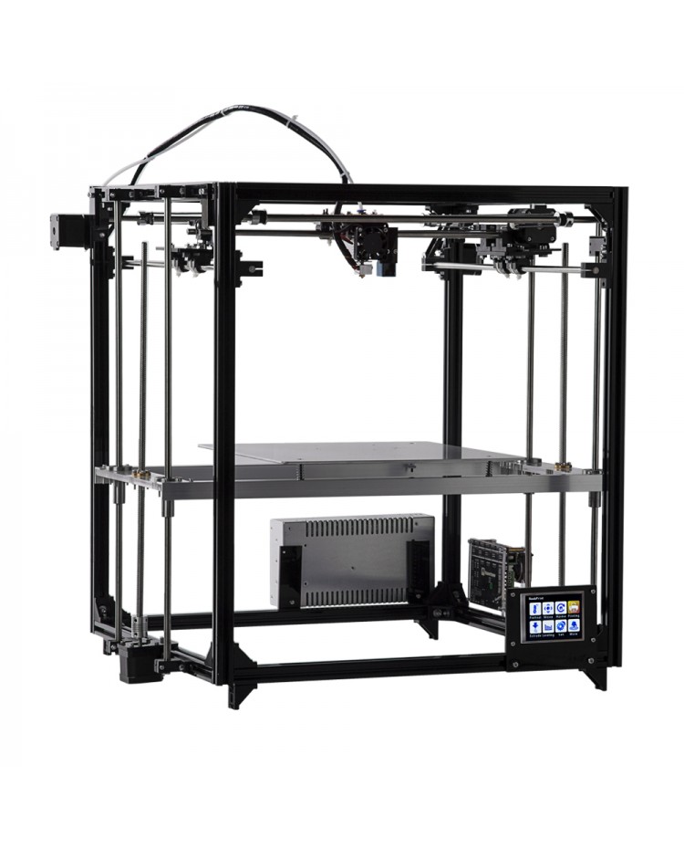 Choose the cube that is printed with the highest P and T parameters, but that no waves can be seen on it. The number in parameter P will be the desired acceleration value. To save this value, you need to find 2 lines in the firmware:
#define DEFAULT_MAX_ACCELERATION {X,Y,Z,E0}
#define DEFAULT_ACCELERATION {nnn}
Instead of X and Y, you should put an acceleration twice as high as found earlier. And instead of nnn, you need to put the acceleration value found earlier. Otherwise, you need to insert a line in the initial GCODE:
M204 Pnnn Tnnn
In the parameters P and T, you need to put the value of the found acceleration. After that, the acceleration setting can be considered complete.
Jerk
A jerk indicates the speed with which to start accelerating. It affects the model in a similar way as acceleration: it creates ripples around the corners of the model. But it also increases the protrusion of the corners if the jerk is too small.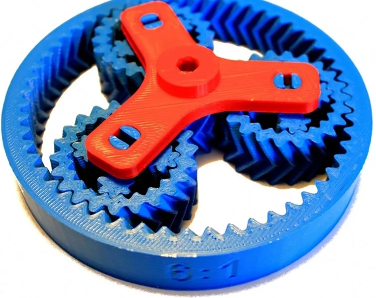 The jerk setting is also similar to the acceleration setting:
-
Cut a model of a standard test cube with a wall thickness equal to one nozzle diameter, without filling and top layers, bottom 2-3 layers.
-
Open GCODE file in notepad
-
Find the G28 command at the very beginning and insert the line data after it:
M205 X5 Y5
-
Save the changes, print the model according to the received GCODE and note at what X and Y parameters it was printed
-
Open the same GCODE file and change the X and Y values on the second line, adding 2 to each
-
Repeat steps 4-5 at least 3 times
As a result, you will get several cubes. Find a non-rippled cube printed at the highest X and Y settings. This will be the jerk value for your printer. To save them, you need to find the line in the firmware:
#define DEFAULT_XJERKnnn
#define DEFAULT_YJERKnnn
It is necessary to substitute the jerk values for the X and Y axes, respectively. Otherwise, you need to substitute the command in the starting GCODE:
M205
Instead of nnn, you need to substitute the jerk value found earlier. This completes the jerk setting.
Speed
In fact, there are many different speed parameters, the values \u200b\u200bof which vary greatly. Let's take a look at the main ones:
This parameter is responsible for moving the nozzle without extruding plastic. The value is in the range from 80 to 120 mm/s. Limited only by the maximum speed at which the motors can rotate. Does not affect the model
This speed is important because it indirectly affects the adhesion of the model to the table. Usually lies between 15 and 30 mm/s
-Print speed of inner walls
Usually set to about 60 mm/s, it only affects the strength of the model. Depends on the maximum amount of plastic that the extruder can push through the nozzle
-Speed of printing outer walls
Usually about half the printing speed of the inner walls (30 mm / s).