3D printer extruder assembly
5. Extruder Assembly | Prusa Knowledge Base
EN
- Čeština
- Español
- Italiano
- Deutsch
- Polski
- Français
Login
- Home
- MK2S
- Assembly manuals
- Original Prusa i3 MK2S kit assembly
- 5. Extruder Assembly
- Original Prusa i3 MK2S kit assembly
- 1. Introduction
- 2. Y-axis assembly
- 3. X-axis assembly
- 4. Z-axis assembly
- 5. Extruder Assembly
- 1. Get the necessary tools
- 2. 3D printed parts
- 3. [TIP] Top nut insertion
- 4. Placing the nuts
- 5. Preparing the extruder body
- 6.
Preparing the extruder cover
- 7. Placing the extruder cover
- 8. Preparing the extruder motor
- 9. Mounting the motor and the idler
- 10. Tighten the motor screws gently.
- 11. Tightening the pulley
- 12. VIDEO for step 11
- 13. Prepare the Extruder idler
- 14. Preparing shaft with bearing
- 15. Prepare the Extruder idler screws
- 16. Placing the screws
- 17. Preparing the Front print fan
- 18. Preparing the fan nozzle
- 19. P.I.N.D.A. probe preparation
- 20. P.I.N.D.A probe and print fan cables preparation
- 21. The P.I.N.D.A. probe tighting
- 22. Mounting the Left hotend fan
- 23. Preparation for step 24
- 24. Preparing for extruder mounting on the X-axis
- 25. Extruder cables preparation
- 26. Arranging extruder cables
- 27. Securing extruder in place
- 28. Cable management
- 29. Cable management - right side
- 30. Attachment of the Extruder cable holder
- 31.
 Tighten the Extruder cable holder
 - 32. Preparing the filament
- 33. Spiral wrap ziptie
- 34. Finalizing the extruder
- 35. All done!
- 6. LCD assembly
- 7. PSU & Heatbed assembly
- 8. Electronics assembly
- 9. Preflight check
Relevant for
:
MK2S
Last updated
3 years ago
Difficulty
Moderate
Steps
35
Available languages
Step 1 Get the necessary tools
⬢2.5 and 1.5 mm Allen key
⬢Needle-nose pliers
Step 2 3D printed parts
⬢Extruder-cover
⬢Extruder-body
Attention! Starting August 2017 there is a redesigned P.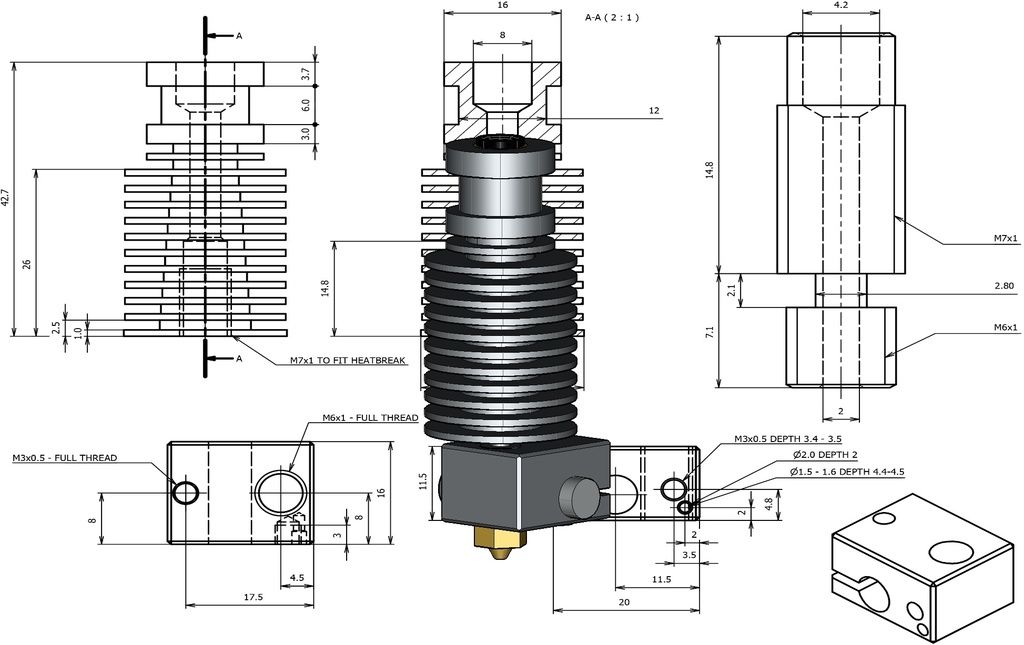 I.N.D.A. probe holder, remaining parts of Extruder-body are unchanged. See the second picture.
⬢Extruder-idler
⬢Fan-nozzle (can be in black color, dimensions are the same).
⬢Extruder-cable-holder
Printed parts are in the bag labeled "E-AXIS".
Step 3 [TIP] Top nut insertion
If you're experiencing troubles with getting nut into the top hole, just follow these simple steps.
⬢Screw M3 nut a bit on a long screw (M3x40 from 9.SPARE bag works in most cases).
⬢Push the screw with the nut into the hole where it is supposed to be.
⬢Grab the screw with pliers and gently hammer the nut in place using a wrench.
Step 4 Placing the nuts
⬢Place the M3 nuts (2 pcs) into the traps on the left side of the extruder body.
⬢Slide the M3nS square nuts (4 pcs) into the traps on the right side of the extruder body.
Place the nuts as deep as possible.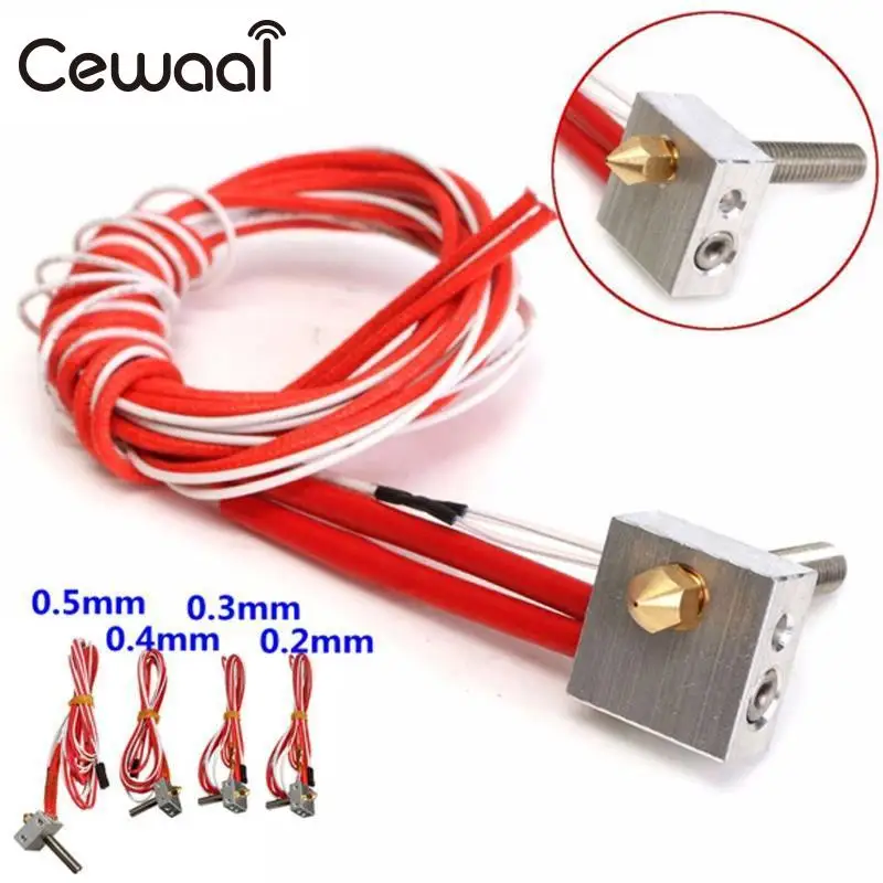
Ensure you have placed all nuts (from both sides of the body).
Step 5 Preparing the extruder body
⬢Slide the extruder body on the nozzle as shown in the picture.
⬢Push the nozzle all the way down and make sure that cables are on the side as shown in the picture.
Be careful with all extruder cables from now on.
Step 6 Preparing the extruder cover
⬢Place the M3 nuts (2 pcs) into the traps of the extruder cover.
Top nut needs to be pushed all the way down! (the nut trap has 2 diameters, only last 3 mm have correct diameter for the nut trap).
Step 7 Placing the extruder cover
⬢M3x18 (1 pc)
⬢M3x25 (1 pc)
⬢Mind the correct orientation of cables leading from the extruder heater.
⬢Using the 2.5mm Allen key tighten both screws to mount the extruder cover on the extruder body.
Make sure to use the proper length of screws when mounting the extruder cover. Check all nuts are in their places.
Tighten until the nozzle stops moving in the extruder, if there's still a gap between the cover and the body it's alright.
The M3x18 screw needs to reach just the first square nut. The second square nut is for a different screw used in another step.
Step 8 Preparing the extruder motor
⬢Press the pulley on the motor.
The screws must be facing directly against the pad (flat part) on the shaft.
If you're experiencing trouble, loose the grub screw a bit.
⬢Note the correct orientation (the screw has to be closer to the motor).
Don't tighten the pulley at the moment, we have still time for that.
Step 9 Mounting the motor and the idler
⬢M3x30 screws (2 pcs)
⬢Don't forget to have the idler in place (the screw has to go through it).
⬢Mount the motor on the the extruder body as shown in the picture, double check proper orientation of the motor cables.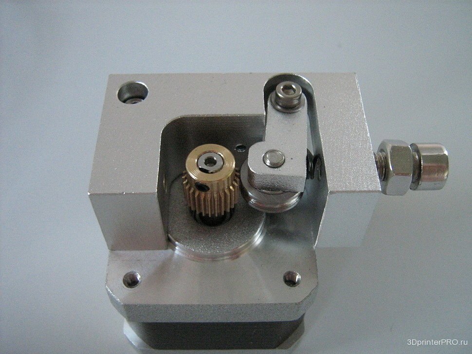
Mind the correct orientation of motor cables.
Step 10 Tighten the motor screws gently.
⬢Tighten the motor screws gently.
Step 11 Tightening the pulley
⬢Using the 1.5mm Allen key tighten the pulley.
Make sure that the part with smaller diameter is perfectly aligned with the nozzle entrance.
Make sure the pulley can rotate freely.
Use a piece of 1,75 mm filament (from the spool) to align the pulley with the openings for the filament (see the picture).
Step 12 VIDEO for step 11
Your browser does not support HTML5 video.
⬢Using the 1.5mm Allen key tighten the pulley. Make sure that the part with smaller diameter is perfectly aligned with the nozzle entrance. Use a piece of filament to align the pulley with the openings for the filament.
Video is available in an online (digital) version only.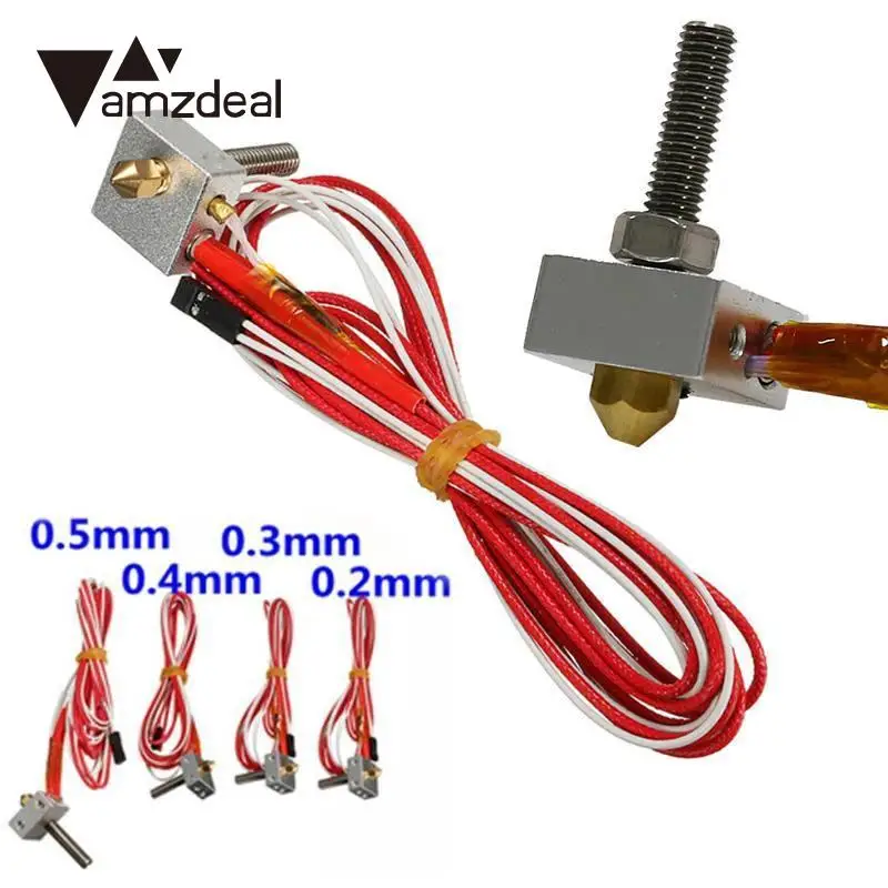
Step 13 Prepare the Extruder idler
⬢Place the M3nS square nuts (2 pcs) into the traps of the extruder body.
Step 14 Preparing shaft with bearing
⬢5x16sh shaft
⬢M5w washer (2 pcs)
⬢625 bearing (1 pc)
⬢Place the washers and bearing on the shaft as shown in the picture.
⬢Place the shaft with bearing into the idler.
Check the shaft is pressed all the way in!
Step 15 Prepare the Extruder idler screws
⬢M3x40 screw (2 pcs)
⬢M3w washer (4 pcs)
⬢Extruder spring (2 pcs)
⬢Assemble the screws as shown in the picture.
Step 16 Placing the screws
⬢Screw the extruder screws into the extruder body using the 2.5 mm allen key as shown in the picture.
Length of the springs should be circa 13 mm when tightened.
It is alright to tighten the screws with higher force, we need to induce pressure on the idler.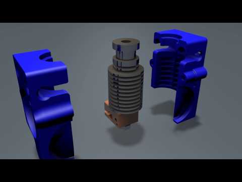
Step 17 Preparing the Front print fan
⬢5015 print fan
⬢M3x20 screws (2 pcs)
⬢Screw the fan on to the extruder using the 2.5 mm Allen key as shown in the picture.
Do not tight fully at this moment, fan should just be secured in place.
Front print fan is in the box 2.3.4.5.SUP
Step 18 Preparing the fan nozzle
⬢Fan nozzle
⬢M3x20 screw (1 pc)
⬢Tighten the fan nozzle using the 2.5 mm Allen key. Gently tighten screws holding up the fan in place.
DON'T tighten the screws too hard, all parts are made of plastic and you can break them.
Double check that the fan can rotate freely.
Step 19 P.I.N.D.A. probe preparation
⬢Prepare the P.I.N.D.A. probe (autocalibration) by removing both of the nuts (if included in delivery)
P.I.N.D.A. probe is in the 2.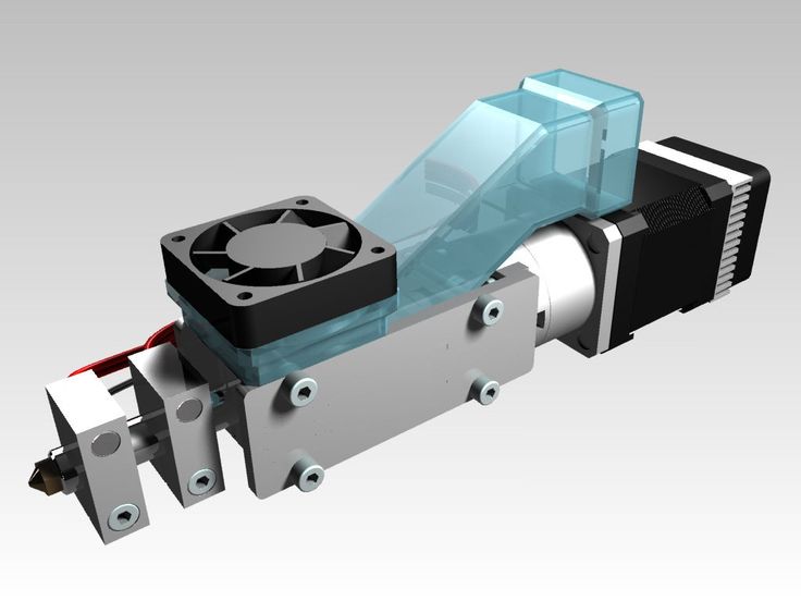 3.4.5.SUP box.
Step 20 P.I.N.D.A probe and print fan cables preparation
⬢Pass the P.I.N.D.A. probe through the mount.
⬢Guide both cables through a cable clip on the extruder body as shown in the picture.
Exact position of the P.I.N.D.A. probe will be adjusted later (in Chapter 9, Preflight check), so there is no need to adjust or tighten fully at this point.
⬢The best position for mounting at this point is to align the last thread of the probe with the end of the mount
Note the loop on the cable from the probe, it's necessary to apply it correctly!
Step 21 The P.I.N.D.A. probe tighting
⬢Secure the P.I.N.D.A. probe with M3x10 screws
Note the loop on the cable from the probe, it's necessary to apply it correctly!
New design of the holder requires only one screw M3x10. See the last picture.
Step 22 Mounting the Left hotend fan
⬢M3x18 screws (4 pcs)
Note the correct orientation of the fan.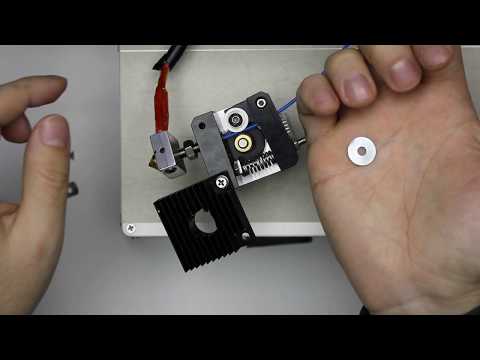 The sticker has to face towards the nozzle!
⬢Guide cables from the extruder motor via slot in the extruder body, put the fan in place.
⬢Using M3x18 screws mount the fan to the extruder body using the 2.5mm allen key as shown in the picture.
⬢Tighten fan screws gently using the 2.5 mm Allen key.
The Left hotend fan is in the box 2.3.4.5.SUP
Step 23 Preparation for step 24
⬢M3x40 (1 pcs) with M3n nut (1 pcs)
Printed manual might suggest to use screw M3x30, but the correct is M3x40.
⬢Screw the nut fully
Step 24 Preparing for extruder mounting on the X-axis
⬢M3x40 screws (1 pcs)
⬢M3x30 screw (1 pcs)
⬢M3x18 screw (1 pcs)
⬢M3x40 (1 pcs) with M3n nut (1 pcs)
Pay attention to use proper screws as indicated in the picture.
⬢Place the M3n nut (1 pcs) into the trap
Step 25 Extruder cables preparation
⬢Guide cables from the extruder as in the picture.
Cables from the P.I.N.D.A. probe, the extruder motor and both fans must pass the X-axis between the lower smooth rod and the X-axis belt.
Step 26 Arranging extruder cables
⬢Arrange cables from the extruder upper part neatly in extruder cable holders.
⬢Make sure the cables from the extruder motor are guided as shown in the picture
Step 27 Securing extruder in place
Please tighten the screws in the order described below:
⬢First, tighten the top screw. Don't tighten it fully!
⬢Now tighten the left screw. This one you can tighten fully.
⬢Tighten the right screw fully and then return to the top screw and tighten it as well.
⬢After tightening all screws mentioned above tighten the last screw, which will be used for cable management.
Step 28 Cable management
⬢Guide the cables as shown in the picture.
⬢Make sure that the wires from the thermistor are going above the heater wires.
⬢Running them below will cause issues later, don't do that!
Step 29 Cable management - right side
⬢Insert a ziptie (longer one in package) in the right side of the X-carriage so that cables from the extruder motor and the fan are below the ziptie and held in place.
Double check the orientation of the ziptie.
⬢Once all cables are neatly arranged, finalize it by tightening the ziptie and cutting off the excessive piece.
Use pliers to cut off any excess ziptie.
Step 30 Attachment of the Extruder cable holder
⬢Extruder cable holder
⬢Make sure the cable holder is oriented upwards.
⬢Place the two halfs of the cable stiffener on the M3x40 screw.
Step 31 Tighten the Extruder cable holder
⬢Use two zip ties for fastening.
Use pliers to cut off any excess zip tie.
Step 32 Preparing the filament
Starting mid of February 2018, there will be only one 50cm NYLON filament included.
⬢There are two NYLON filaments included in the kit with lengths 50 and 30 cm. Both have Ø 3 mm. For this step please use the longer one and DON'T CUT any of them!
Push it all the way down. If you experience difficulties when inserting the filament use pliers to make a sharp tip on the filament.
The filament is for the support of the whole harness. Don't cut it, it'll go all the way with the wires to the cover for electronics.
Note the correct orientation of nylon filament, it needs to point up as shown in the picture!
Nylon filament is pictured in orange colour, but in your kit can be the black version, which is the same, just different colour.
Step 33 Spiral wrap ziptie
⬢Wrap the spiral wrap (the largest and the longest one) around the cables and the nylon filament.
⬢Start with cables from the upper part, after 1 turn add cables from the hot end.
Double check by moving the extruder fully to the left or right that spiral wrap does not interfere with the printer frame.
⬢Use zip ties and tighten the wrapped cables and spiral wrap. Tight the spiral wrap to the cable stiffener.
⬢Use one piece at the beginning of the spiral wrap.
Tighten zip ties carefully, too much pressure can damage cables inside! Don't tighten the zip tie over cables only!
Step 34 Finalizing the extruder
⬢Check for free movement of the X-carriage and inspect cables in the full left and right positions.
⬢Once you are satisfied with organisation of the extruder cables finalize spiral wrap to the full length.
⬢Separate the filament at the last whirl of the spiral wrap.
Step 35 All done!
⬢Congratulations! You've just assembled the extruder.
⬢You can continue by assembling the LCD in the next chapter - 6. LCD assembly
Was this guide helpful?
Easy to understand
Solved my problem
Other reason
Comments
Still have questions?
If you have a question about something that isn't covered here, check out our additional resources.
And if that doesn't do the trick, you can send an inquiry to [email protected] or through the button below.
5. Extruder Assembly | Prusa Knowledge Base
- Home
- MK2S
- Assembly manuals
- Original Prusa i3 MK2 kit assembly
- 5. Extruder Assembly
- Original Prusa i3 MK2 kit assembly
- 1. Introduction
- 2. Y-axis assembly
- 3. X-axis assembly
- 4. Z-axis assembly
- 5. Extruder Assembly
- 1. Get the necessary tools
- 2. 3D printed parts
- 3. [TIP] Top nut insertion
- 4. Placing the nuts
- 5. Preparing extruder body
- 6. Preparing the extruder cover
- 7. Placing the extruder cover
- 8. Preparing the extruder motor
- 9. Mounting the motor and idler
- 10. Tightening the pulley
- 11. VIDEO for step 11
- 12. Prepare the Extruder idler
- 13. Preparing shaft with bearing
- 14. Prepare the Extruder idler screws
- 15.
 Placing the screws
 - 16. Preparing the print fan
- 17. Preparing the fan nozzle
- 18. P.I.N.D.A. probe preparation
- 19. P.I.N.D.A probe and print fan cables preparation
- 20. P.I.N.D.A. probe mounting
- 21. Mounting the fan
- 22. Tighten fan screws
- 23. Preparing for extruder mounting on X-axis
- 24. Extruder cables preparation
- 25. Arranging extruder cables
- 26. Securing extruder in place
- 27. Preparing the filament
- 28. Cable management - right side
- 29. [OPTION1] Cable management - part one
- 30. [OPTION1] Cable management - part two
- 31. [OPTION2] Cable management - hot end cables
- 32. Finalizing x-carriage cable management
- 33. Finalizing cable management
- 34. [OPTIONAL] P.I.N.D.A. protector assembly
- 35. Preparing the spiral wrap
- 36. Spiral wrap ziptie
- 37. Finalizing extruder
- 38. All done!
- 6. LCD assembly
- 7. PSU & Heatbed assembly
- 8.
 Electronics assembly
 - 9. Preflight check
Relevant for
:
MK2S
Last updated
3 years ago
Difficulty
Moderate
Steps
38
Available languages
Step 1 Get the necessary tools
⬢2.5 and 1.5 mm Allen key
⬢Needle-nose pliers
Step 2 3D printed parts
⬢Extruder cover
⬢Extruder body
⬢Extruder idler
⬢Fan nozzle (can be in orange color, dimensions are the same).
Step 3 [TIP] Top nut insertion
If you're experiencing troubles with getting nut into the top hole, just follow these simple steps.
⬢Screw M3 nut a bit on some long screw (M3x40 works best).
⬢Push the screw with the nut into the hole where it is supposed to be.
⬢Grab the screw with pliers and gently hammer the nut in place using a wrench.
Step 4 Placing the nuts
⬢Place the M3 nuts (2 pcs) into the traps on the left side of the extruder body.
⬢Slide the M3nS square nuts (2 pcs) into the traps on the right side of the extruder body.
Place the nuts as deep as possible.
Step 5 Preparing extruder body
⬢Slide the extruder body on the nozzle as shown in the picture.
⬢Push the nozzle all the way down and make sure that cables are on the side as shown in the picture.
Step 6 Preparing the extruder cover
⬢Place the M3 nuts (2 pcs) into the traps of the extruder cover.
Top nut needs to be pushed all the way down! (the nut trap has 2 diameters, only last 3 mm have correct diameter for the nut trap).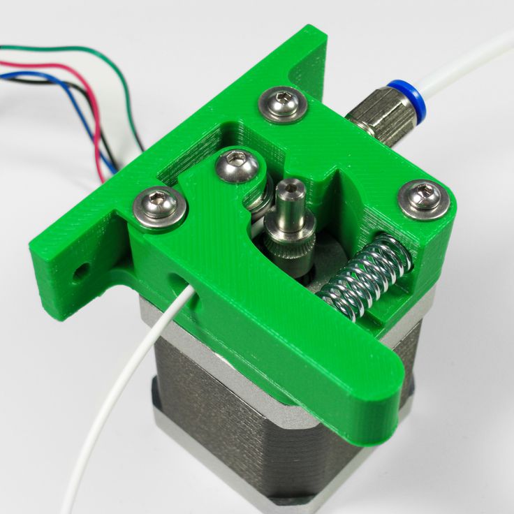
Step 7 Placing the extruder cover
⬢M3x18 (1 pc)
⬢M3x25 (1 pc)
⬢Mind the correct orientation of cables leading from the extruder heater.
⬢Using the 2.5mm Allen key tighten both screws to mount the extruder cover on the extruder body.
Make sure to use the proper length of screws when mounting the extruder cover.
Tighten until the nozzle stops moving in the extruder, if there's still a gap between the cover and the body it's alright.
Step 8 Preparing the extruder motor
⬢Press the pulley on the motor.
If you're experiencing trouble, loose the grub screw a bit.
⬢Note the correct orientation (the screw has to be closer to the motor).
Don't tighten the pulley at the moment, we have still time for that.
Step 9 Mounting the motor and idler
⬢M3x30 screws (2 pcs)
⬢Mount the motor on the the extruder body as shown in the picture, double check proper orientation of the motor cables.
⬢Tighten the motor screws gently.
Don't forget to have the idler in place (the screw has to go through it).
Mind the correct orientation of motor cables.
Step 10 Tightening the pulley
⬢Using the 1.5mm Allen key tighten the pulley.
Make sure that the part with smaller diameter is perfectly aligned with the nozzle entrance.
Use a piece of filament to align the pulley with the openings for the filament (see the picture).
Step 11 VIDEO for step 11
Your browser does not support HTML5 video.
⬢Using the 1.5mm Allen key tighten the pulley. Make sure that the part with smaller diameter is perfectly aligned with the nozzle entrance. Use a piece of filament to align the pulley with the openings for the filament.
Video is available in an online (digital) version only.
Step 12 Prepare the Extruder idler
⬢Place the M3nS square nuts (2 pcs) into the traps of the extruder body.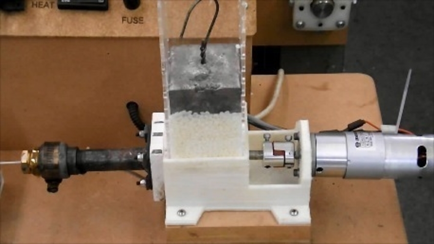
Step 13 Preparing shaft with bearing
⬢5x16sh shaft
⬢M5w washer (2 pcs)
⬢625 bearing (1 pc)
⬢Place the washers and bearing on the shaft as shown in the picture.
⬢Place the shaft with bearing into the idler.
Check the shaft is pressed all the way in!
Step 14 Prepare the Extruder idler screws
⬢M3x40 screw (2 pcs)
⬢M3w washer (4 pcs)
⬢Extruder spring (2 pcs)
⬢Assemble the screws as shown in the picture.
Step 15 Placing the screws
⬢Screw the extruder screws into the extruder body using the 2.5 mm Allen key as shown in the picture.
Length of the springs should be circa 13 mm when tightened.
It is alright to tighten the screws with higher force, we need to induce pressure on the idler.
Step 16 Preparing the print fan
⬢5015 print fan
⬢M3x20 screws (2 pcs)
⬢Screw the fan on to the extruder using the 2.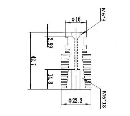 5 mm Allen key as shown in the picture.
Do not tight fully at this moment, fan should just be secured in place.
Front fan is in the box 2.3.4.5.SUP
Step 17 Preparing the fan nozzle
⬢Fan nozzle
⬢M3x20 screw (1 pc)
⬢Tighten the fan nozzle using the 2.5 mm Allen key. Gently tighten screws holding up the fan in place.
Double check that the fan can rotate freely.
Step 18 P.I.N.D.A. probe preparation
⬢Prepare P.I.N.D.A. probe (autocalibration) by removing one of the nuts.
Step 19 P.I.N.D.A probe and print fan cables preparation
⬢Guide both cables trough cable clip on the extruder body as shown in the picture.
Step 20 P.I.N.D.A. probe mounting
⬢Mount P.I.N.D.A. probe in place.
⬢Secure P.I.N.D.A. probe with nut.
Exact position of P.I.N.D.A. probe will be adjusted later (during the printer calibration described in 3D Printing Handbook), so there is no need to adjust or tighten fully at this point.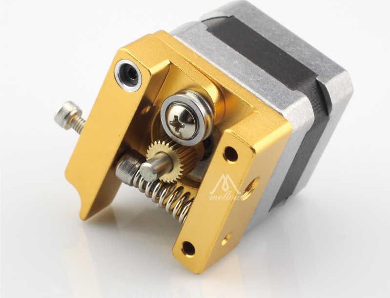
⬢The best position for mounting at this point is to align the end of the probe with the end of the hook on the extruder body.
Note the loop on cable from probe, it's necessary to do it like that!
Step 21 Mounting the fan
⬢M3x18 screws (4 pcs)
Note the correct orientation of the fan. The sticker has to face towards the nozzle!
⬢Guide cables from the extruder motor via slot in the extruder body, put the fan in place.
⬢Using M3x18 screws mount the fan to the extruder body using the 2.5mm Allen key as shown in the picture.
Left fan is in the box 2.3.4.5.SUP
Step 22 Tighten fan screws
⬢Tighten fan screws gently using the 2.5 mm Allen key.
Step 23 Preparing for extruder mounting on X-axis
⬢M3x40 screws (1 pc)
⬢M3x30 screw (1 pc)
⬢M3x18 screw (1 pc)
Pay attention to use proper screws as indicated in the picture.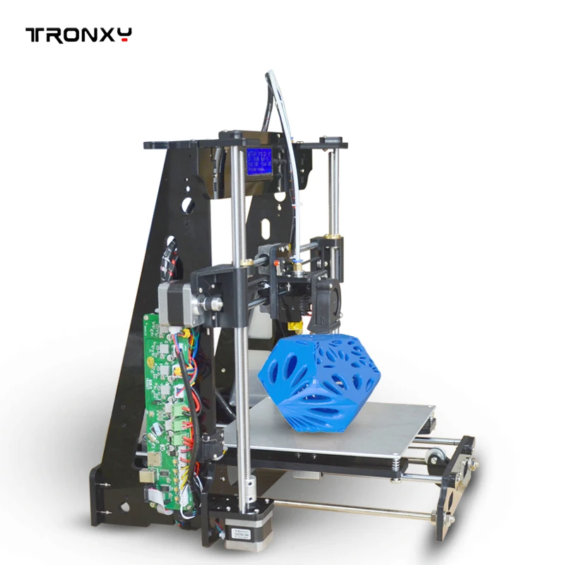
Step 24 Extruder cables preparation
⬢Guide cables from the extruder as in the picture.
Cables from P.I.N.D.A. probe, extruder motor and both fans must pass X-axis between lower smooth rod and X-axis belt.
Step 25 Arranging extruder cables
⬢Arrange cables from the extruder upper part neatly in extruder cable holders.
⬢Ensure the cables are placed in the channel behind left fan, otherwise there is a risk of breaking them (see photo with blue arrows).
Step 26 Securing extruder in place
⬢Tighten the extruder in place using 2.5 mm Allen key.
Step 27 Preparing the filament
⬢Take the piece of filament that came with the parts (NYLON Ø 3 mm, about 50 cm long).
Push it all the way down. If you experience difficulties when inserting the filament use pliers to make a sharp tip on the filament.
The filament is for the support of the whole harness.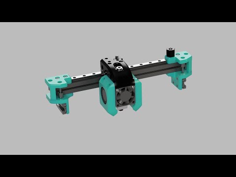 Don't cut it, it'll go all the way with the wires to the electronics.
Step 28 Cable management - right side
⬢Insert ziptie (longer one in package) in the right side of the X-carriage so that cables from the extruder motor and the fan are below ziptie and held in place.
Double check the orientation of the ziptie.
Step 29 [OPTION1] Cable management - part one
⬢If you have a connector on the thermistor cable, this option is for you. If you don't, go for OPTION2.
⬢Guide the cables from the nozzle as shown in the picture.
While handling the thermistor with the connector, make sure that it's still connected!
Step 30 [OPTION1] Cable management - part two
⬢Guide the cables as shown in the picture.
⬢Make sure that the wires from the thermistor are going above the heater wires.
⬢Running them below will cause issues later, don't do that!
Step 31 [OPTION2] Cable management - hot end cables
⬢Revert a ziptie below hot end cables and guide the ziptie up on the left side of the X-carriage.
If you have troubles guiding the cables from hotend, you can cut out the ziptie holding them together.
Cables from P.I.N.D.A. probe and the print fan must be located under the ziptie to keep them in place.
Cables from the nozzle heater are fragile, handle them with extra care!
Step 32 Finalizing x-carriage cable management
⬢Once all cables are neatly arranged finalize it by tightening the ziptie and cutting off the excessive piece.
Step 33 Finalizing cable management
⬢Use a ziptie to secure cables and filament together.
The ziptie must be as close as possible to the X-carriage in order not to interfere with the printer frame.
Step 34 [OPTIONAL] P.I.N.D.A. protector assembly
⬢Prevents rare damage to the probe when a print accidentally lifts up. If you do not have this part, download and print it from http://www. prusa3d.com/printable-parts and mount it later.
⬢Screw in the P.I.N.D.A. protector on the probe.
⬢Make sure that the end of the probe is in line with the protector as shown in the picture.
Step 35 Preparing the spiral wrap
⬢Wrap the spiral wrap (the largest and the longest one) around the cables.
⬢Take nylon with upper cables (both fans, motor, P.I.N.D.A.) and make 1 turn with spiral wrap around them, then add remaining cables and continue with wrapping. (see the picture)
Double check by moving the extruder fully to the left or right that spiral wrap does not interfere with the printer frame.
Step 36 Spiral wrap ziptie
⬢Use zipties and tighten the wrapped cables and spiral wrap.
⬢Use one piece at the beginning of the spiral wrap, second one just after join of all cables.
Tighten zip ties carefully, too much pressure can damage cables inside!
Step 37 Finalizing extruder
⬢Check free movement of the X-carriage and inspect cables in the full left or right position.
⬢Once satisfied with organisation of extruder cables finalize spiral wrap to the full length.
Step 38 All done!
⬢Congratulations! You've just assembled the extruder.
⬢You can continue by assembling the LCD in the next chapter - 6. LCD assembly
Was this guide helpful?
Easy to understand
Solved my problem
Other reason
Comments
Still have questions?
If you have a question about something that isn't covered here, check out our additional resources.
And if that doesn't do the trick, you can send an inquiry to [email protected] or through the button below.
Correct assembly of the extruder for a 3D printer
Technician
Good afternoon. I want to share with you some secrets of assembling an extruder for a 3D printer, which will greatly simplify your life in terms of working with it.
I have assembled Anet A6 myself and am completely satisfied.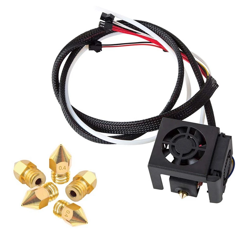 The 3D printer has already eaten about 5 kg of plastic without any problems or hitches. I leave the seal at night and when I leave for work.
All extruders that print plastic from a rod have the same principle of operation and the rules for anet A6 will be valid for other printers. We need 'thread for sealing threads' (not for sealing), thermal paste and our own
hands.
I must say right away that sealing against leaks of molten plastic occurs between the nozzle and the thermal barrier, nowhere else.
If this unit is correctly assembled, then the molten plastic will never leak and burn out on the heating element and nozzle, which means there will be no burning smell.
Let's start in order.
We do not completely screw the nozzle into the thermoblock with a heater, we do not screw it in about 1 mm as in the photo.
Then we screw the thermal barrier with the sealing thread all the way into the nozzle
At the point of contact between the nozzle and the thermal barrier, sealing occurs.
The thread sealing thread is needed so that during the change of the nozzle the heating block does not rotate on the thread of the thermal barrier, this eliminates the possibility of the thermocouple moving out of its regular place. After changing the nozzle, tighten it with a force of about 500 grams per 10 cm. Do not forget that the nozzle rests not on the thermal block, but on the thermal barrier.
Lubricate the heating element and the thermocouple with thermal paste before installation in the block.
This will allow your printer to maintain the set temperature within + or - 1 degree.
It will also significantly extend the life of the heating element.
I hope this information will be useful to you. Good luck everyone.
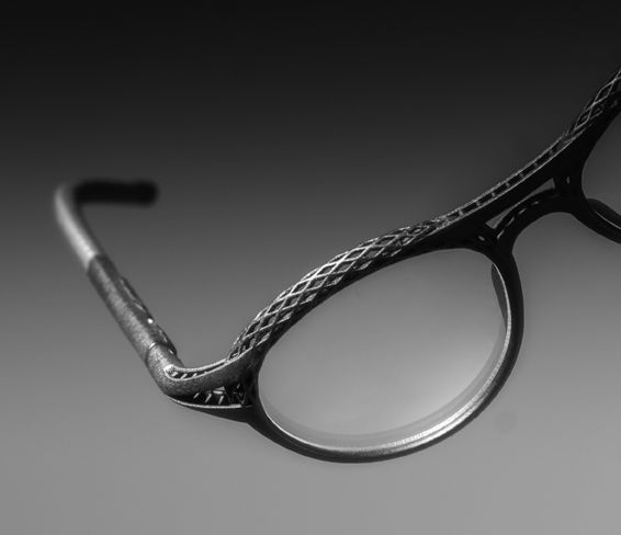
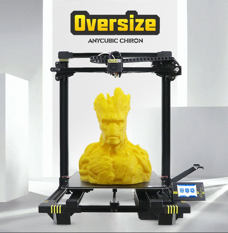
Some products printed on Anet A6
Subscribe to the author
Subscribe
Don't want
15
More interesting articles
9
Subscribe to the author
Subscribe
Don't want
Hello everyone.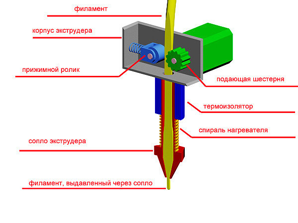 Recently I found a new way for myself to get rid of the plug in the printer...
Read more
one
Subscribe to author
Subscribe
Don't want
0003
Read more
197
Subscribe to the author
Subscribe
Don't want
Hi all!
As Seryoga already announced, I'm starting to publish a series of articles on assembling...
Read more
3D Printer Extruder - Complete Manual Heatle
Learn the basics of direct drive and Bowden extruders, hot and cold ends, nozzle sizes and materials, and find the best 3D printer cartridge for your needs.
The 3D printing process of can be briefly described as follows: a filament of plastic material is fed into a heated metal block with a nozzle, where it is melted and extruded in a given form. This path is repeated, gradually building up until a solid three-dimensional object is formed.
The entire business task of handling the material, melting it and exiting for printing takes place in a block called 3D printer extruder .
In this article, we will look at the main sections of the 3D printer extruder, the options and advantages of different styles of extruders, popular models on the market, as well as cartridge heaters for 3D printers and other items.
What is an extruder
The 3D printer extruder is a set of parts that together process and move a plastic filament.
Some consider the extruder to be just the motor and associated parts that push and pull the filament, others the entire assembly including the heated part that melts and deposits the filament.
For simplicity, this article treats the entire assembly as an extruder. To begin with, while explaining the key components of a 3D printer extruder, we will divide it into two elements: a cold zone and a hot zone.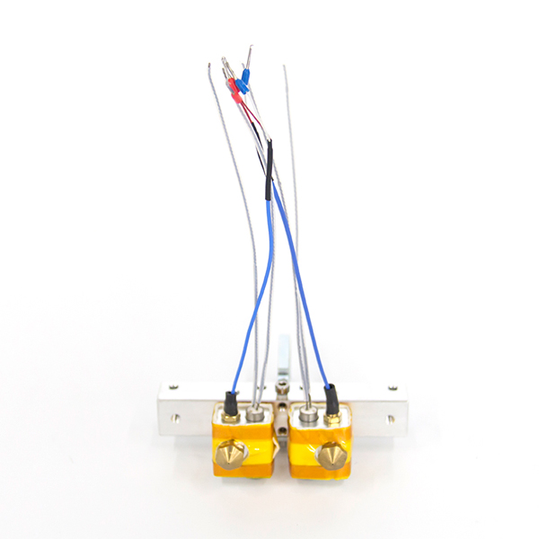
Cold zone
As the name implies, the cold zone is exactly that - cold. This is the top of the 3D printer extruder system, where the filament is fed into and then passed into the hot zone to be melted and extruded onto the print bed.
The appearance and location of the cold zone on your 3D printer depends on whether it is a direct drive or Bowden drive extruder (both of which are detailed below).
There is no filament heating here. The cold zone consists of the extruder motor and gear train, which are usually mounted either on the printer frame or on the print head itself, depending on the type of extruder, and a PTFE tube to smoothly guide the filament into the hot end.
What happens in the cold zone?
With the heatsink removed on this e3D Titan Aero, we can see the inner workings of the 3D printer's extruder.
Essentially, the cold zone consists of a stepper motor, some form of gear, a toothed bolt or gear, a spring-loaded idler (usually a bearing of some kind) to hold the filament, and then a PTFE tube to guide the filament.
A humble stepper motor with a metal gear required for a 3D printer's extruder drives the filament extrusion in most if not all modern desktop 3D printers.
However, one stepper motor is not enough to feed the filament to the hot end. The parts attached to and operating the stepper motor drive shaft must physically grab the filament and push it on its way to the hot end.
In this cutaway view of a 3D printer extruder, we see a metal gear and a plastic gear with a toothed shaft.
This usually uses a combination of toothed gears and toothed bolts or shafts (in the image above we see a metal gear and a plastic gear with a toothed shaft) serving as a pressure wheel along with a bearing or other rigid frictionless material.
Here we see a plastic lever with an integrated bearing, an extension spring and a plastic gear with a toothed shaft. Together they apply pressure to the filament and force it through the extruder.
Alternatively, there are versions of the cold end of the 3D printer extruder that use a slightly different arrangement of parts to feed the filament. Such deviations are often claimed to provide increased traction and yarn delivery.
Here we see both sides of the Prusa i3 Mk3 cold end, including the Bondtech extruder gear train.
As mentioned, there are varieties of 3D printer extruder that use these parts in slightly different layouts. Each has its pros and cons. Next, we will look at what is the difference between a direct drive 3D printer extruder and a Bowden 3D printer.
Direct drive extruders
The Direct Drive 3D Printer Extruder is different in that it places the extruder motor directly above the heating unit. This arrangement minimizes the travel distance of the filament to the hot end and can enable more reliable 3D printing of flexible filaments.
The advantage of using direct drive is more precise retraction control.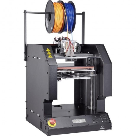 Due to the location directly above the hot end, there is less distance between the clamp and the thread passing through the thermal barrier into the heating block. Consequently, the filament has less room to bend and deform under pressure.
Bowden extruders
Bowden Style 3D Printer Extruder The does not mount directly on the top of the hot end like a direct drive 3D printer extruder, but the motor and gear assembly mounts on the frame of the printer. This gives this type of extruder an advantage over its head-mounted direct drive brother: speed.
By placing the mass of the 3D printer's extruder on the frame instead, the printhead is freed up to print at higher speeds without sacrificing print quality.
A side effect of placing the 3D printer's extruder this way is that the filament now has to travel a long way in a tube that's a fraction wider than it is. There should be enough room along the entire length of the tube for a slight bend in the thread. When pulling in the thread between strokes, this slack in the thread shortens the pull-in distance. Without correction (i.e., an increase in retraction), this results in a delay in relieving the pressure exerted on the hot end. In short, you can get confused if you don't change your retract settings.
Heating block (Hotend)
Inside the knot, known as the hot end, the filament passes into a heated chamber where it changes from solid to liquid. Sounds simple, and mostly it is. Although there is a lot more to make the filament silky extrude onto the build plate.
What happens in the heating zone?
The E3D Titan Aero combines a heating block and an extruder in one compact unit. The hot end usually only has the central parts of this image: the heatsink (and fan), the heating element (micro cartridge heater), the heater block, the thermistor, and the nozzle.
A typical 3D printer hotend consists of a specific sequence of parts. There is a slight difference depending on whether you are using PTFE/PEEK or a full metal hot end. Here we explain the all-metal hot block.
First, it is a filament supply tube. In both a Bowden 3D printer extruder and a direct drive extruder, it will just be a PTFE tube coming from your cold filament feeder.
You can sometimes find direct drive 3D printer extruders where the filament runs straight into the print head.
On a Bowden 3D printer's extruder, this feed tube inserts the filament directly into the thermal barrier via a heatsink. The thermal barrier that is screwed into the heatsink is often a threaded stainless steel (or other non-conductive metal such as titanium) tube.
Split in two (note the two separate threads in the image below - longer for the heatsink, shorter for the heater block) and machined on the inside, the thermal break allows the filament to pass freely into the extrusion nozzle.
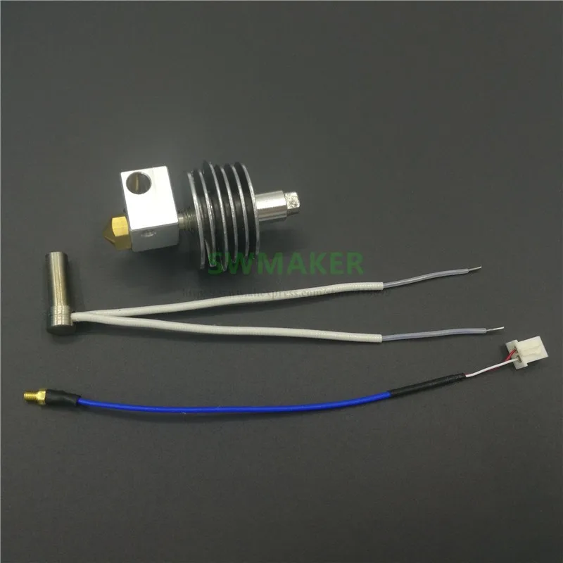
Clockwise from bottom left: steel thermal barrier, aluminum heating block and brass nozzle.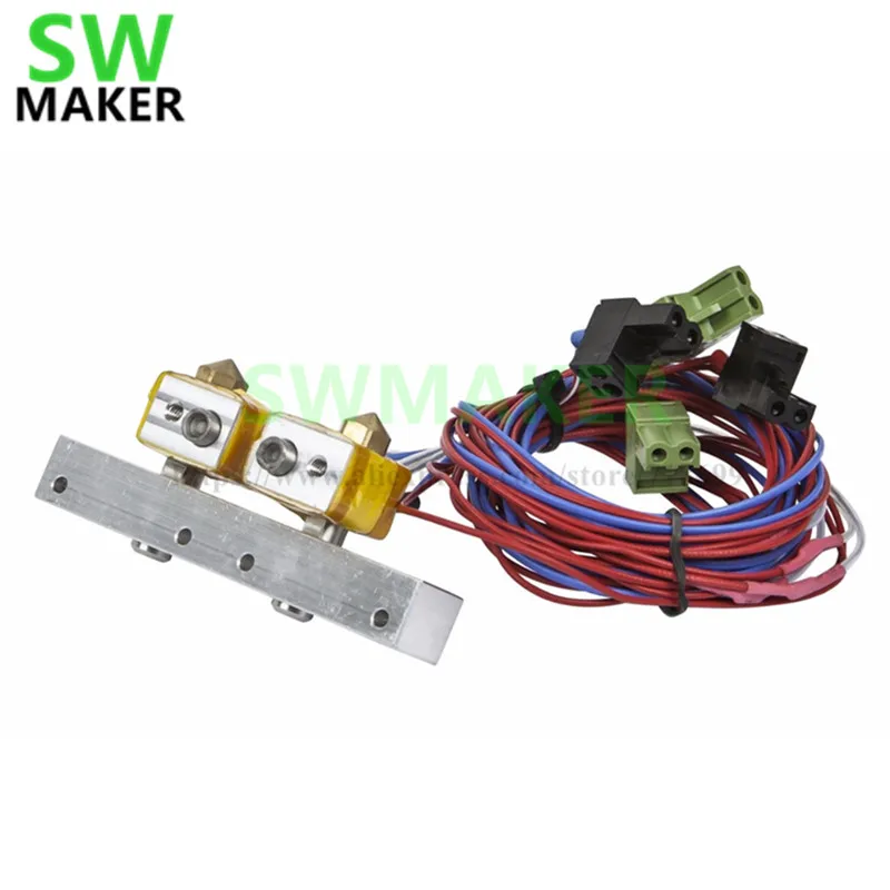
But since we're dealing with precision and a material that liquefies for rapid recooling, the 's temperature management is critical. The thermal barrier, in combination with the heat sink, maintains a certain limit at which the filament is exposed to high temperatures.
The top, which is actively cooled by a heatsink and dedicated fan, prevents heat from escaping from the hot end and weakening the filament before it is where it needs to be for extrusion. This unwanted phenomenon is known as thermal creep.
The lower part of the thermal barrier is located inside the heater block together with the cartridge heater, the temperature switch thermistor and the nozzle.
The heater block, usually made of aluminum, ensures a smooth transition of the filament from the open end of the thermal break tube to the nozzle.
The temperature to melt the filament has to come from somewhere, and this is where the cartridge heater comes into play.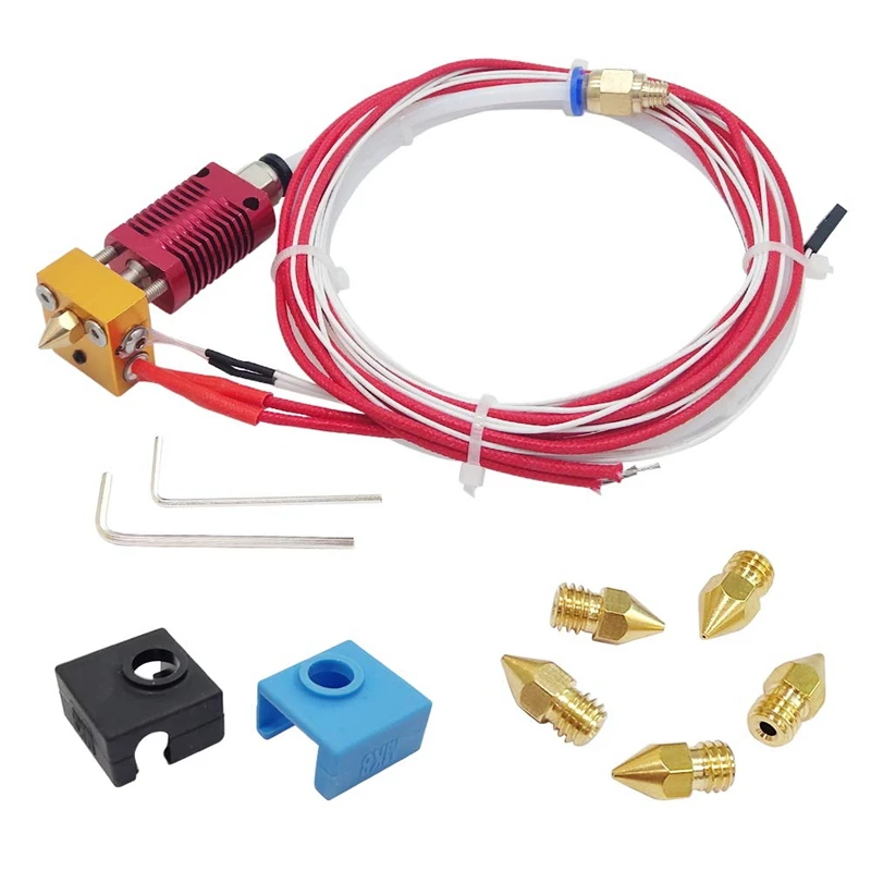


.jpg)