3D printer enclosure wood
3d Printer Enclosure Wood Frame
Etsy is no longer supporting older versions of your web browser in order to ensure that user data remains secure. Please update to the latest version.
Take full advantage of our site features by enabling JavaScript.
-
Loading
Click to zoom
644 sales |
5 out of 5 stars €26. 82
Loading
VAT Included
Listed on Nov 9, 2022
389 favorites
Report this item to Etsy
Choose a reason…There’s a problem with my orderIt uses my intellectual property without permissionI don’t think it meets Etsy’s policiesChoose a reason…
The first thing you should do is contact the seller directly.
If you’ve already done that, your item hasn’t arrived, or it’s not as described, you can report that to Etsy by opening a case.
Report a problem with an order
We take intellectual property concerns very seriously, but many of these problems can be resolved directly by the parties involved. We suggest contacting the seller directly to respectfully share your concerns.
If you’d like to file an allegation of infringement, you’ll need to follow the process described in our Copyright and Intellectual Property Policy.
Review how we define handmade, vintage and supplies
See a list of prohibited items and materials
Read our mature content policy
The item for sale is…not handmade
not vintage (20+ years)
not craft supplies
prohibited or that use prohibited materials
not properly labeled as mature content
Please choose a reason
Tell us more about how this item violates our policies.Tell us more about how this item violates our policies.
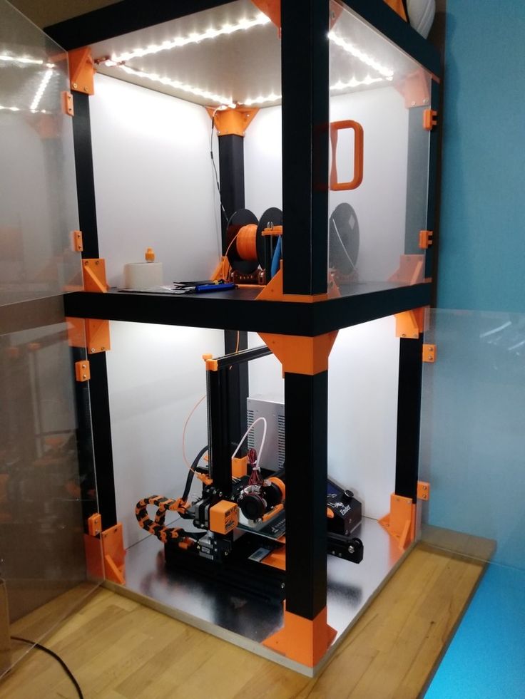
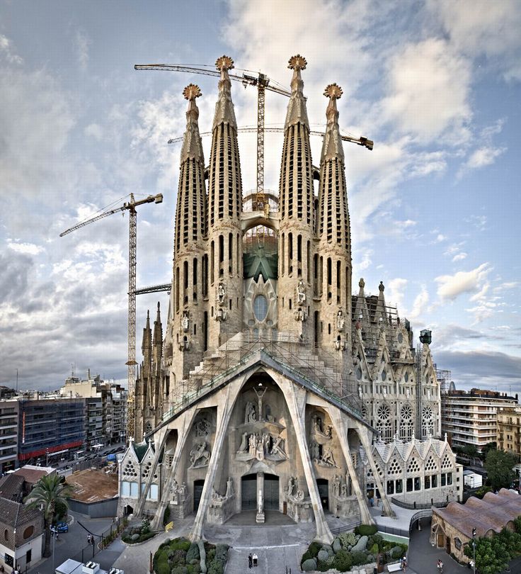
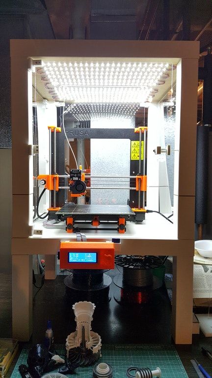
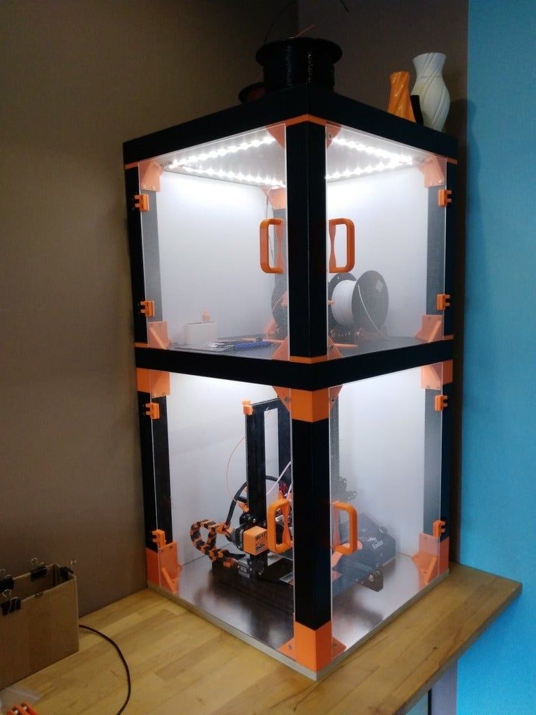
Build a 3D Printer Enclosure
Today, something slightly off-topic. This post is a short tutorial on how to build a heavy and solid 3D-printer enclosure. It uses a fully parametric design, where you can adjust the important dimensions – therefore it should work with a wide range of 3D-printer and materials.
Update 1: Added some photos, illustrating the process.
Update 2: Added more photos of the process.
The tools you need
- Fusion360 (Free for personal use, download here)
- For the wood boards:
- Tools to cut wood boards to exact and square dimensions.
- Hardware store with a board cutting service.
- For the acrylic glass:
- Tools to cut the sheets into exact shapes (CNC or laser)
- Alternatively, order them pre-cut (recommended).
- Four, short, adjustable metal feet/legs. A height of 50 – 150mm should work. I do not recommend casters.
- Pencil, meter, set square and some experience in woodworking.
- Power-drill with 4mm and 5mm ⌀ drills.
- Woodscrews with a countersunk head:
- 5mm × 50 mm (example)
- 4mm × 40 mm (example)
- Clamps, ideally some clamping squares.
I assume you already build a few objects out of wood, so I do not have to tell you how to cut wood or screw two boards together in a right angle.
My original design was made for an Original Prusa I3 MK3S printer.
Step 1: Chose the boards
Use heavy wood boards for the base, with a thickness from 20mm – 30mm. Do not use solid wood boards, but either plywood or particle boards. The base has two functions: It is used for storage of filament, but it provides the required stability to absorb vibrations from the printer.
The enclosure uses two of the heavy boards as bottom and top for stability, but lighter boards around the enclosure to make the best use of the enclosed space. Use boards with a thickness from 8mm – 12mm. Again, do not use solid wood, but either plywood, particle boards or similar.
It is important these boards will keep its dimensions and do not start to bend or buckle. The 3D-printer will produce some heat and therefore the enclosure will be exposed to a constant temperature change. Solid wood would be a really bad choice for this use case.
Now select two wood types and write down the thickness of each.
Step 2: Adjust the 3D Model
Download the 3D-Model and open it in Fusion 360.
Open the parameters in the model (Modify → Change parameters):
First, adjust the thickness for the base (Parameter BaseWoodThickness), then adjust the thickness for the enclosure (Parameter EnclosureFrameWoodThickness). Just click into the Expression field of the parameter and write your new value and unit. The model will adjust automatically.
Next, adjust the main dimensions:
| Parameter | Minimum | Maximum |
|---|---|---|
| BaseWoodThickness | 20mm | 30mm |
| EnclosureFrameWoodThickness | 8mm | 12mm |
| FeetHeight | 10mm | 150mm |
| PlatformHeight | 600mm | 1500mm |
| PlatformWidth | 500mm | |
| PlatformDepth | 500mm | |
| EnclosureHeight | 500mm |
- Start with the height of the adjustable feet/legs. Adjust the parameter FeetHeight.
- Next, chose the height of the platform, where the printer is placed. If you have a table with a height you are comfortable with, use this height. Adjust the parameter PlatformHeight.
- Now check the required dimensions of your 3D-printer. Make sure you add enough space around the printer for e.g. printer-bed movements, attached filament spools, etc.
- Write these dimensions down as width, depth and height.
- Add two times the thickness of the enclosure boards to the width and depth. Also, add two times the thickness of the boards of the base to the height.
- Adjust the last parameters:
- PlatformWidth ← width
- PlatformDepth ← depth
- EnclosureHeight ← height
At this point, the model should automatically be adjusted to the new dimensions.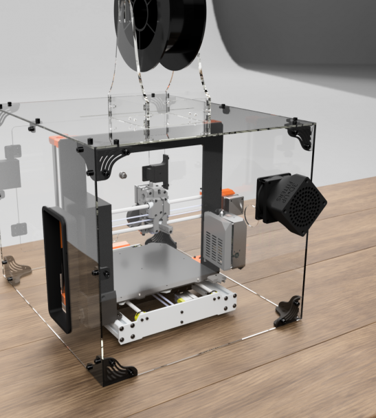 Check the timeline at the bottom of the windows for any errors or warnings. If you get some, check the parameters are in the valid ranges above.
Step 3: Extract the Dimensions
On the left side, you find all components in the object browser:
I numbered all required parts with a three digit number.
- Use a paper or your favourite spreadsheet program to note the dimensions of all components.
- Right-click on a component, e.g. “101 Bottom”, and select “Isolate” from the menu. Now you see just this component on the screen.
- Use the Inspect → Measure tool to extract the width and height of each required part.
- Write down the part number and measurements.
- Also, write down the thickness or material for each entry.
- Repeat for every component. Check each dimension twice!
- Now you can count boards of the same material and dimensions to simplify a material order.
Here an example table with all original dimensions:
| Part Names | Count | Thickness (mm) | Width (mm) | Height (mm) |
|---|---|---|---|---|
| 101, 102 | 2 | 22 | 600 | 600 |
| 103, 104 | 2 | 22 | 806 | 600 |
| 105, 106 | 2 | 22 | 568 | 556 |
| 107 | 1 | 22 | 806 | 556 |
| 201, 203 | 2 | 10 | 150 | 600 |
| 202, 213 | 2 | 10 | 600 | 600 |
| 204, 205 | 2 | 10 | 70 | 600 |
| 206, 209 | 2 | 10 | 60 | 600 |
| 211, 212 | 2 | 22 | 580 | 580 |
| 207, 208 | 2 | 5 | 358 | 598 |
| 210 | 1 | 5 | 474 | 594 |
Step 4: Cut or order the boards
Now cut all boards to the noted dimensions, make sure the angles of the boards are perfectly square.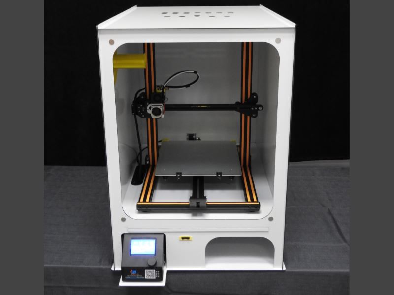 If you ordered the boards pre-cut, check if the angles are square.
Add rounded corners to the acrylic glass, a radius of 5-10mm should be enough. This is especially important for the front door. Also, trim any sharp corners.
Step 5: Assemble the Base
Start with the frame of the box. Parts 101, 102, 103 and 104.
Fix two boards using clamping squares, drill holes and fasten the boards using a minimum five evenly spaced screws. Check the angle of the two boards before you continue.
Continue with the other boards until you get the box as shown above.
Now insert the back, part 107. You may need to remove some material if your boards are thicker as calculated.
Fasten the back board with evenly spaced screws around all four sides.
Add the shelves at your desired heights.
The most difficult way, with the best stability, is to screw the shelves into place from the sides. It requires you to mark the height of a shelf inside of the box and the centerline for the screws at the outside.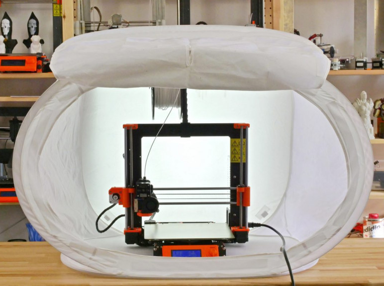 If you are confident at woodworking, I recommend this method to add extra stability to the base.
Alternatively use brackets or (not recommended) pegs to fasten the shelves in the box.
Finally add the feet/legs to the base. Done!
Step 6: Assemble the enclosing
Start with the base plate and back side, parts 202 and 211.
Assemble the two boards using clamping squares or an angle bracket. Don’t tighten the screws too much, the angle doesn’t need to be perfect at this stage.
Now add the sides, part 201 and 203.
Fasten the two parts with two or three screws to the base plate. Make sure these parts are in a perfectly right angle to the base plate.
Prepare the top frame, part 212.
Now fasten the top frame, part 212 to the back plate, part 202.
Now fasten the left and right boards, part 201 and 203 to the back plate, part 202. Use 4mm screws to connect the thinner boards. Make sure everything is in a perfect right angle. Don’t fasten the left and right boards to the top frame yet.
Next add parts 204 and 205.
Fasten the two parts using screws at the base plate and top frame. Check if all parts are in a right angle to each other. Next, fasten parts 201 and 203 to the top frame, part 212.
Add the front panels, part 206 and 209.
Finally add the acrylic glass panels.
Best use soft transparent silicone sealant to fasten the two panels into place. If you use screws, make larger holes into the acrylic glass, to allow some wood expanding and shrinkage. If this fit is too tight, the glass may break.
Now check the fit of the top cover, part 213.
Drill holes in all four corners and add pegs to align the top cover with the top frame. With the pegs, the top cover can be easily removed if necessary.
Step 7: Add the front door
Fastening the front door should be the last step. I prepared a fully parametric design for 3D printed hinges. By default, they are designed to use M5 screws with cylindric heads, and 4mm wood screws.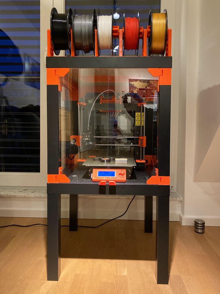 They should be work fine, but you may want to choose a different/own design.
- Print the four parts twice to produce two hinges.
- Assemble both hinges with the M5 screw as the axis.
- Fasten the two hinges to the wood panel on the front. Make sure they are attached in a perfect right angle and are flush with the wood.
Now place the enclosure on the back.
Carefully align the acrylic glass of the front door with even spacing around all four edges. Use masking tape to lock the glass in the right location. Now mark the locations of the holes for the hinge.
Drill the 6mm holes for the M5 screws of the hinge, this will give some room for an alignment of the glass plate.
Add a door knob of your favourite design to the right side of the door.
Done!
- Stack the enclosure on the base.
- Put the printer into the enclosure.
The two elements, the base and enclosure aren’t connected for a good reason. Add a heavy rubber mat between these two parts to decouple vibrations from the printer to the floor or the other way around.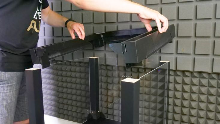
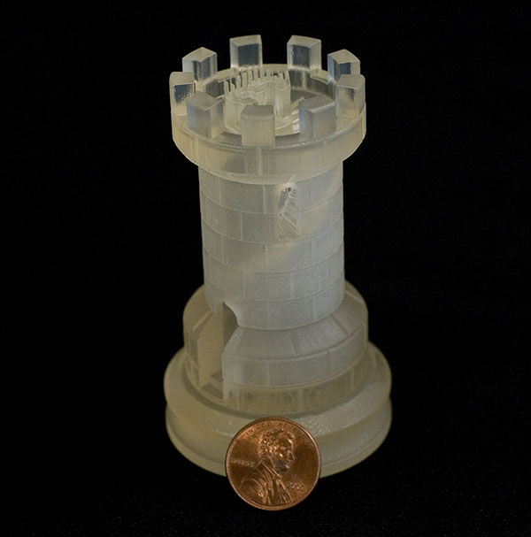
I hope you enjoyed this short, off-topic tutorial and it inspired you to build your own enclosure for your 3D printer.
If you have any questions, missed any information, or simply want to provide feedback, feel free to comment below. 😄
More Posts
Get Blog Updates With the New Mailinglist
In a few days, I will stop using Twitter for project notifications. If you like to get notified about new projects and updates, please subscribe to the new mailing list: It is a low-frequency mailing ...
Read More
How to Create a Large 3D Printed Artwork
I recently built a relatively large (100cm × 80cm) 3D printed artwork, which features a painted relief of mathematical functions. Read how I prepared the data, converted it into 3D printable tiles and converted them ...
Read More
Large Update to the Circle Pattern Generator
Today I published a significant update to the circle pattern generator. Version 1.4.1 of the application is available for macOS and Windows for download.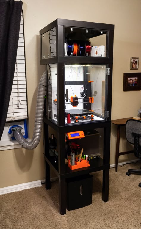 This new version adds various shapes, rotations, colours and a generator ...
Read More
Update to the Storage Boxes System
Last week I sent all subscribers a small update to my storage boxes system. There are new split boxes for the tall boxes (LR2052-300C-S) and a new extensive PDF catalogue with a great overview, but ...
Read More
Build a Sustainable Refillable Active Coal Filter
If you ever used air filters to keep smells, fumes and dust at a low level in your workshop, you for sure came in contact with these expensive throwaway active coal filters. While throwing-away the ...
Read More
Huge Storage Boxes Update
Today I release a huge update of my storage boxes system for 3d-print. This update not only further improves the geometries of the models, but also extend the available sizes and variants. There are now ...
Read More
3D Printer Case Rigidity
Printing on my Wanhao Duplicator i3 Mini, I realize more and more that I lack its capabilities.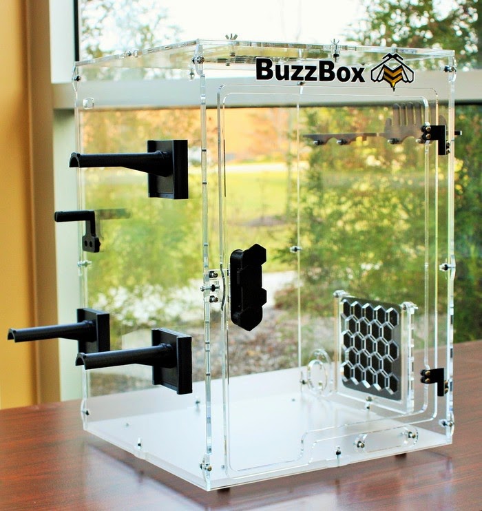 And its print area is small (120 x 135 x 100), and there are restrictions on the materials used. In this regard, and with my ever-growing interest in the designs of various printers, there was a desire to make my own 3D printer, and not buy a ready-made more advanced one.
And the first thing I started with was thinking about the design of the hull.
For those who prefer to watch in video format, here is a link to the video.
There are a wide variety of 3D printer case designs, and in my opinion, the essential characteristic of any case will be its rigidity. Experienced makers recommend using two options as a case:
- frame made of metal sheets;
- structural profile frame.
At the same time, it is considered that it is better to leave printed parts in the housing design. If there are printed parts in the case design, then such a 3D printer will have some restrictions on maximum accelerations and printing speed.
I have not seen any quantitative comparisons of the rigidity of printer cases. As a rule, all the results are obtained empirically from people who have independently assembled far from one 3D printer. In this regard, it became interesting for me to check the static stiffness of various variants of 3D printer cases. I have taken a few of the more common ones. The first case is the Prusa i3 printer case made of steel, the thickness of the material is 3 mm.
The second case considered is the case of the Ultimaker 2 printer. The material is steel, 3 mm thick.
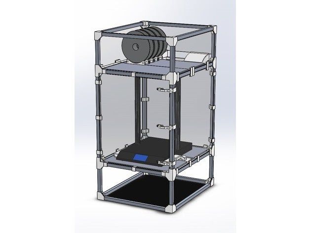
Then I looked at several cases made from a 20x20 mm structural profile. Material - aluminum. Here is the first option:
The second version is reinforced with L-connectors 60x60 mm in size and 2 mm thick
And the last option considered is the hull version, reinforced with diagonal structural elements. At the same time, one of the side walls is open, since work with the 3D printer table is carried out through it.
All models considered have comparable print area sizes, which will clearly demonstrate the difference in rigidity.
Concerning the last version of the homemade housing with diagonal elements, I will do a little demonstration with a children's construction set to show how much diagonals can increase rigidity.
A square truss is made from a children's construction toy. Each of the four nodes of the truss has a hinge and can be easily deformed.
Now let's add a diagonal element.
The truss is then completely immobile, despite the fact that each of its four nodes still has a hinge, i.e. an element with zero torsional rigidity.
Let's move on to the calculation results. All calculations were performed by the finite element method in the free program Z88 Aurora V5. The following scheme was chosen as the design scheme for all printer bodies:
As can be seen from the figure, the bottom of the printer was fixed, and a load of 10 kg was applied to the upper part along the X and Y axes separately.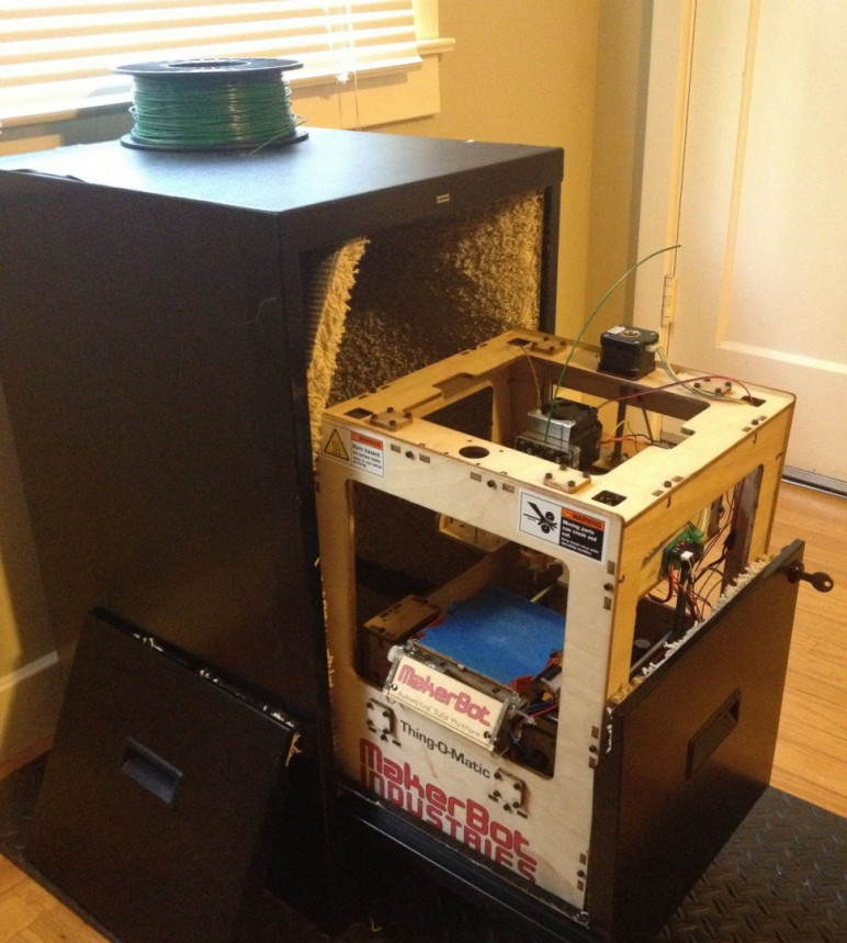 First along the X axis, then along the Y axis. The result of the calculations is the amount of body movement in millimeters. You can watch the animation of the deformation of all the hulls in the video from the beginning of the article.
Results for the Prusa i3 printer body. The scale of deformations is increased for clarity. X-axis deformation:
Y-axis deformation:
Here are the results for the Ultimaker 2 printer body. X-axis deformation:
It can be seen that due to the rigidity of the rear solid wall, the main deformation occurs in the area of the front wall of the housing.
Y-axis deformation:
And now let's move on to the results of calculating the options for housings, often used in homemade 3D printers. The first version does not have any reinforcing elements. Such a design can be roughly considered as a case design, which uses printed connecting elements, the rigidity of which leaves much to be desired.
Due to the fact that the body is symmetrical, the load was applied only once along one axis:
The next version of the self-made case is reinforced with corners, the so-called L-connectors, 60x60 mm in size. Due to symmetry, the load was also applied only once.
As we can see, in comparison with the first version, the amount of deformation has significantly decreased.
And the last version of the self-made body, reinforced with diagonal elements. Since this version of the body is not symmetrical, the load was applied along the X and Y axes. Deformation along the X axis:
It can be seen that there is no significant increase in rigidity along the X axis, in comparison with the version reinforced with L-connectors. At the same time, it can be seen from the figure that the main deformations are concentrated in the front frame of the case, where there is no diagonal element.
Y-axis deformation:
Y-axis distortion is significantly lower and comparable to that of the Ultimaker 2 printer body.
The histogram shows the calculation results for all blocks:
As we can see, the case of the Ultimaker 2 printer turned out to be the winner - the deformation of this case turned out to be minimal. The second place was taken by the Prusa i3 printer case. And then there are various options for a makeshift hull, which are designated as RepRap.
Note the fairly significant difference in stiffness between all the homemade cases and the Prusa i3 and Ultimaker 2 cases. Only the diagonal case homemade case came close to them in terms of stiffness and only along one axis. At the same time, the low rigidity of this option along the X axis is explained by the absence of a diagonal on the front wall.
Next, I will consider several options for strengthening this case in order to increase its rigidity.
Considering that the Ultimaker 2 printer case turned out to be the leader in rigidity, I decided to consider adding a 3 mm thick wall to the front frame of the printer as the first reinforcement option:
This reinforcement made it possible to increase the rigidity of the body along the X axis by approximately two times.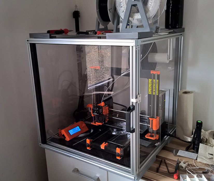
L-connectors 60x60 mm in size have been added to the front panel as the next case reinforcement:
This variant does not increase the body rigidity so much.
As a final revision, a diagonal was added to the top wall of the case:
For this modification, the stiffness was comparable to adding a 3 mm wall to the front panel.
Below is a histogram comparing all the considered options for a homemade case with the Ultimaker 2 printer case.
It can be seen that when creating the body from structural profiles, we failed to achieve a rigidity comparable to the body from sheet material. As close as possible, the variant of the case with diagonal elements and a front panel made of 3 mm sheet turned out to be the closest.
Conclusions from the calculations:
First, the opinion of experienced printer builders is once again confirmed that the case made of sheet metal is the most rigid and durable.
Secondly, it is possible to make a case from structural profiles, but for this we will need to sacrifice the convenience or aesthetic appearance of the case. For example, adding diagonals is not always convenient in terms of the layout of 3D printer elements.
I hope the results will be useful to you. That's all for now.
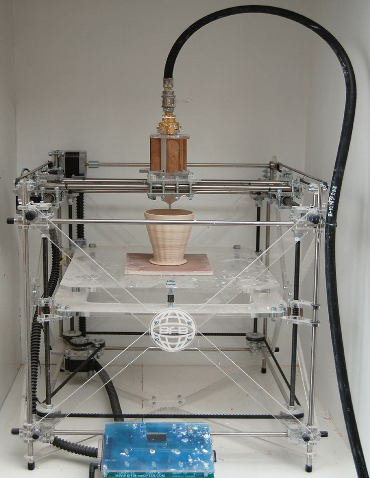
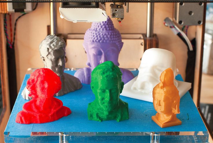
Exploring the features of a 3D printer
Hello everyone! A new RobotON article is devoted to learning how a 3D printer works, reviewing the key components for a 3D printer and assembling this device. Also, this article will help you choose and buy the right 3D printer. We note right away that in this article we will not consider industrial 3D printers, for now we will limit ourselves to home use devices. The most common 3D printer for the home is the Prusa i3 or its replicas. It is on her example that we will analyze the main components of any 3D printer. For simplicity, we divide the device into several parts:
- Frame with rails
- Table
- Extruder
This is the order in which any such device should be assembled.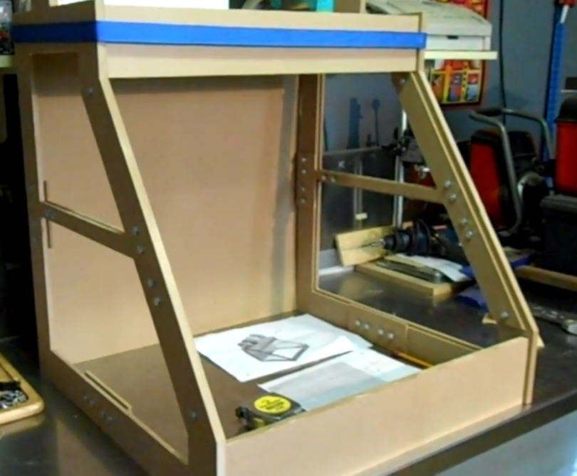 Let's start studying the framework. Despite its simplicity, it greatly affects the quality of 3d printing. The fact is that during operation, a 3D printer makes a huge number of small movements of the extruder and table, driven by stepper motors. Each such movement causes vibrations, which, in order to avoid printing errors (displacements), the body must absorb. That is, the body must be strong, heavy enough and have good rigidity.
Very often, the quality of 3d printing drops when the body elements are skewed. This can be caused by improper assembly (lack of rigid fixation of some elements or excessive tightening of others) or a change in the shape of the case under the influence of various external factors. One of these factors is the thermal change of the material. An example of a bad case is a 3D printer with a plastic or acrylic case.
Often, to improve the quality of printing 3d models, you need to place a 3D printer in a thermally insulated box, which maintains a fairly high temperature (60 degrees and above). Under such thermal influence, the case may begin to deform. Based on such nuances, we can conclude that the best option would be a metal case. Wooden cases are very good compared to plastic ones and they are also often used, as they are easy to cut on simple laser CNC (numerical control machines).
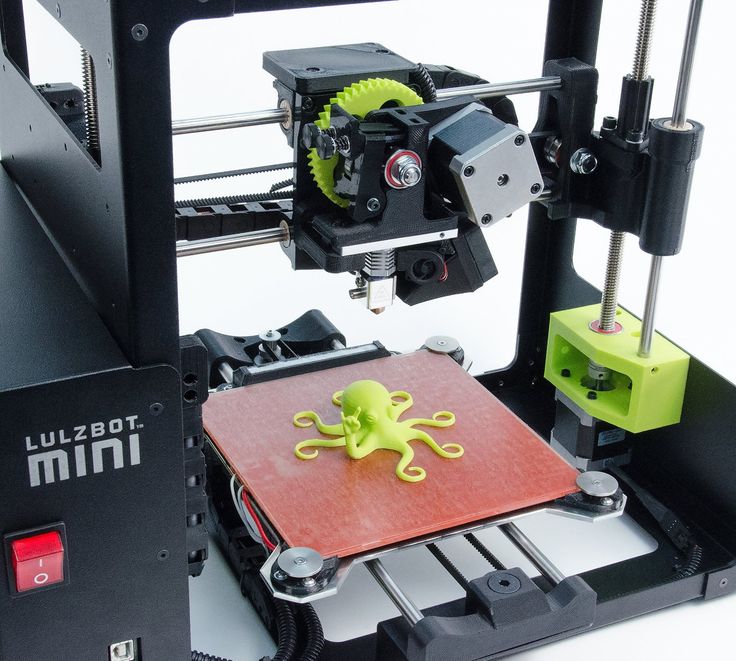
Now let's move on to the guides and motors located on the frame. It makes no sense to describe the assembly of the 3D printer frame, since it consists of inserting structural elements into the grooves and tightening them with bolts and nuts. Then comes the assembly of vertical guides on which the extruder is located (marked in red).
To do this, you first need to install 2 stepper motors in the indicated places on the sides of the frame. After installing the motors and vertical guides, guides with screw threads are installed in the motors, along which the extruder will ride in a vertical plane.
At this point, we can assume that a third of the assembly is completed. Now we need to assemble a table moving in a horizontal plane. To do this, we need to put two guides in the frame, into which slides on ball bearings are pre-threaded, designed to move the table along them. Then we install another stepper motor behind the frame, which will drive the table. To do this, using a belt, we connect the motor shaft and a freely rotating element in front of the frame. We connect the ends of the belt at the bottom of the table. It is very important that this belt is pulled tight, otherwise poor quality 3D printing is guaranteed. You can tension the belt with the help of an additional spring, it is very convenient.
All key elements are illustrated.
Now you need to assemble the extruder. First, let's figure out what it consists of:
- Nozzle
- Heating element (+ holder)
- Thermal decoupling tube
- Radiator with bar pusher
- Accessories and accessories
Now about everything in more detail.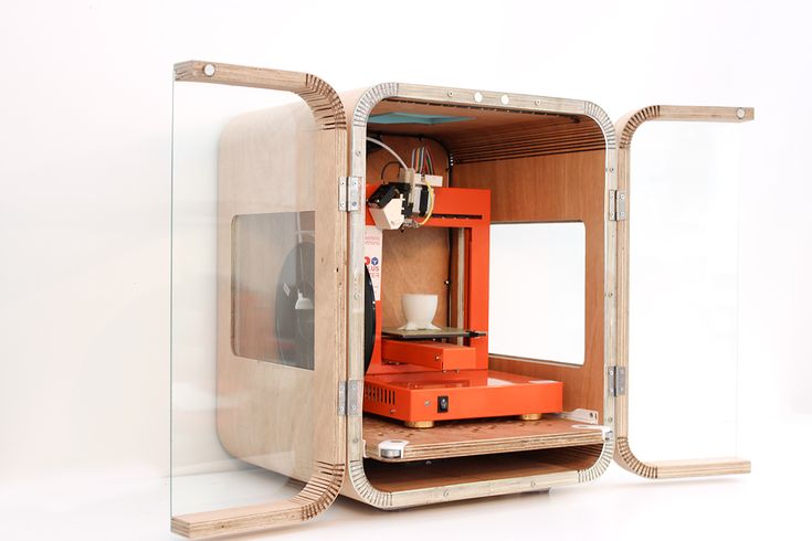 Let's start with the nozzle. It serves as an outlet for molten plastic to the table. The key difference between nozzles is the diameter of the outlet: the smaller it is, the better the print quality and the longer the print itself. Most often, nozzles with a diameter of 0.3 mm are used (the marking on the nozzle is “3.0”). This nozzle is optimal in terms of quality and print time.
Nozzle temperature is an extremely important parameter when printing. It is different for different plastics and it is this value that must be set in the Repetier Host settings before slicing the model. For example, for PLA plastic, the temperature range is within 180-230 degrees, ABS plastic is 230-260. It is also necessary to pay attention to how and where the temperature is determined. The nozzle is heated by the heating element holder (hot end) into which it is screwed. Therefore, for better heat transfer, this element must be made of aluminum. You can often find clamping screws in the hotend holder. In our opinion, only one screw is needed - the one that fixes the heating element and the temperature sensor (thermocouple) together with it. This is where the temperature is measured. The head of the temperature sensor must be inside the hole intended for it. It often happens that during the prototyping process, with poor fixation of the hot end or inattention when installing the thermocouple, the sensor does not touch the aluminum heater holder badly or at all, thereby measuring a much lower temperature. In this case, the printer tries to heat up the hot end more and more. This is easy to see with the eye, because in this case it becomes red hot, and you will immediately smell the burnt plastic. Therefore, in the process of assembling the extruder, you need to be especially careful and accurate.
Next, we move on to the thermal decoupling tube. There are several types, but the best option is to use the following:
- The tube must match the diameter of the plastic rod used.
 So, for example, for the most common 1.75 mm bars, the diameter of the thermal barrier hole (exit hole) will be about 2 mm. True, such a hole should not be all over this element. From the end where the rod enters the thermal decoupling tube, the hole should be slightly larger than 1.75 mm and in no case be larger than 1.9mm. It is also better to choose a thermal barrier with a conical entrance - a plastic rod for a 3D printer will move better. An example of such a tube is shown in the figure.
 - A thermal decoupler must be provided to accommodate the Teflon tube. As shown in the figure, a PTFE or Teflon tube should be installed at one end and abut against the constriction. That is why the thermal barrier must comply with the parameters described above. The thing is that the metal conducts heat perfectly, and the thermal decoupling screwed into the heater holder heats up quite a lot. If there is no fluoroplastic tube, the plastic rod going to the nozzle will begin to melt and lose its rigidity much earlier.
 In this case, it will be very difficult to push the plastic into the nozzle and thus you may not get extrusion at all. To avoid this problem, a Teflon tube is used. This material has very poor thermal conductivity and can withstand high temperatures (many have probably heard of Teflon-coated pans?). Nevertheless, it is still necessary to remove heat from the thermal decoupling, otherwise, after some time, it will heat up to a critical temperature. Therefore, the thermal decoupling tube is screwed into the radiator block with a plastic rod pushing mechanism located inside. A fan is attached to the radiator for cooling. The pushing mechanism is quite simple: with the help of a stepper motor, a wheel is set in motion, tightly pressing the plastic bar on one side. On the other hand, the bar is pressed by another wheel, the degree of "pressure" can be changed by twisting the bolt.
After assembling the extruder, we must place it on a sled similar to that on which the table is mounted.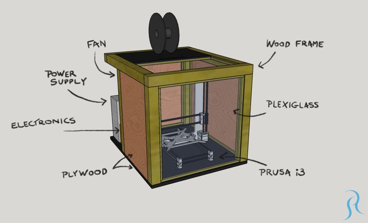 We thread two guides into this sled, the ends of which are connected to the vertical guides of the frame using plastic (possibly even printed stl models for a 3D printer) parts. The last, fifth, stepper motor is attached to one of these parts. Similar to a table, the motor is connected via a belt to the extruder via a freely rotating wheel located on another plastic piece. As in the previous case, the belt must be well tensioned!
Now our printer can move in all three axes: Z - vertical guides of the frame, Y - table, X - movement of the extruder along the horizontal guides. This is enough to print a three-dimensional detail. It remains to install 3 more elements on each of the axes. In order for the printer to be aligned, it is necessary to explain to him where the starting point is. For this, 3 limit switches or, in other words, stoppers are used. We install the first one on one of the vertical guides, the other - on the horizontal one, along which the table rides, and the third one - on the horizontal one, along which the extruder rolls.