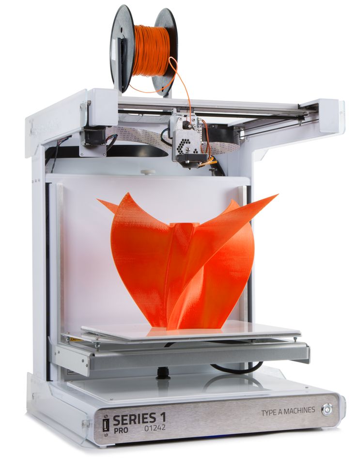
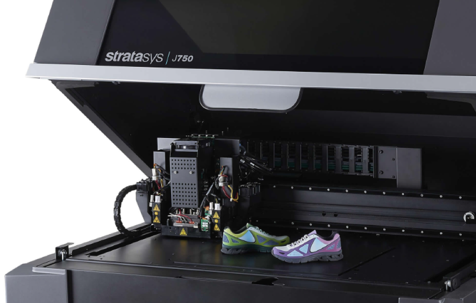
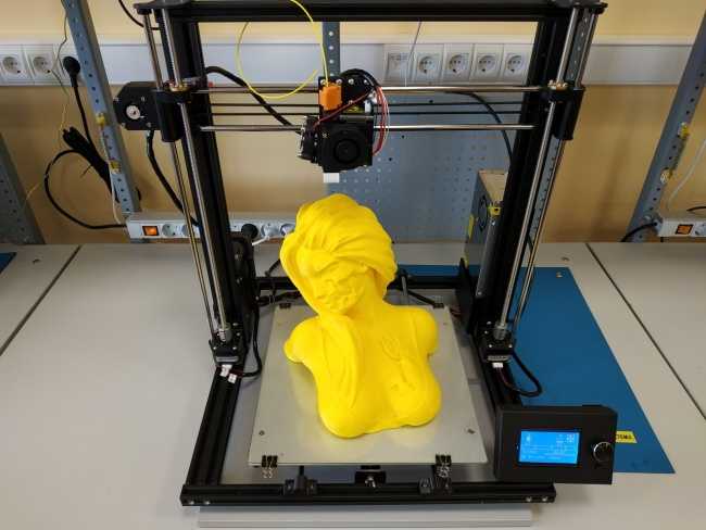
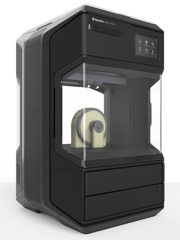
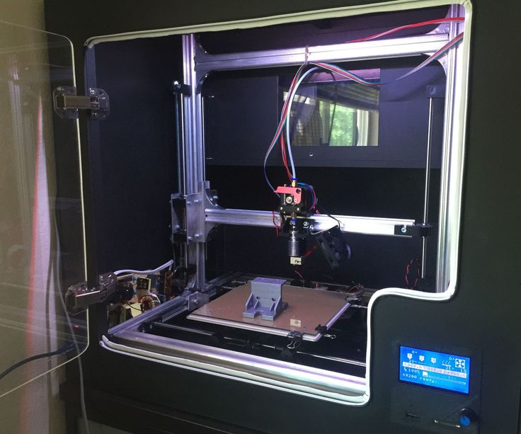
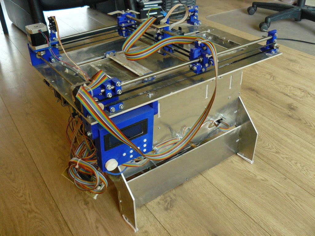
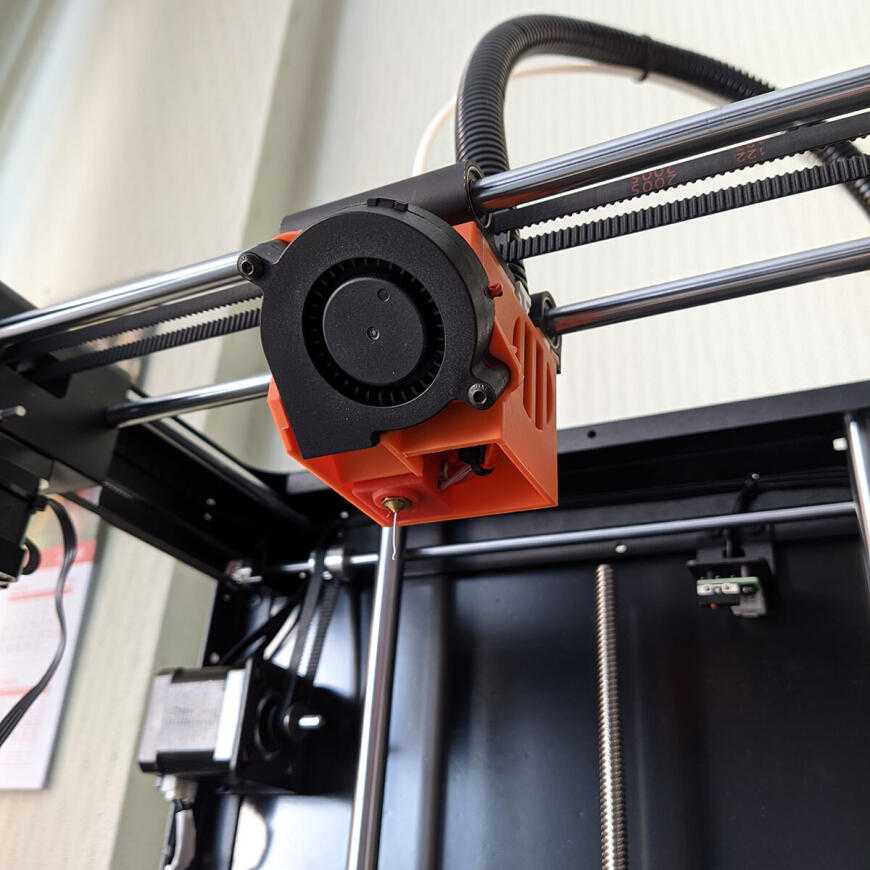
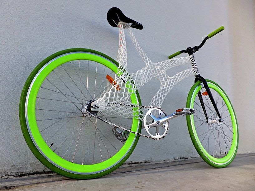
3D printer details
3D Printing Definition
By
Adam Hayes
Full Bio
Adam Hayes, Ph.D., CFA, is a financial writer with 15+ years Wall Street experience as a derivatives trader. Besides his extensive derivative trading expertise, Adam is an expert in economics and behavioral finance. Adam received his master's in economics from The New School for Social Research and his Ph.D. from the University of Wisconsin-Madison in sociology. He is a CFA charterholder as well as holding FINRA Series 7, 55 & 63 licenses. He currently researches and teaches economic sociology and the social studies of finance at the Hebrew University in Jerusalem.
Learn about our editorial policies
Updated November 29, 2021
Reviewed by
Khadija Khartit
Reviewed by Khadija Khartit
Full Bio
Khadija Khartit is a strategy, investment, and funding expert, and an educator of fintech and strategic finance in top universities. She has been an investor, entrepreneur, and advisor for more than 25 years. She is a FINRA Series 7, 63, and 66 license holder.
Learn about our Financial Review Board
Fact checked by
Vikki Velasquez
Fact checked by Vikki Velasquez
Full Bio
Vikki Velasquez is a researcher and writer who has managed, coordinated, and directed various community and nonprofit organizations. She has conducted in-depth research on social and economic issues and has also revised and edited educational materials for the Greater Richmond area.
Learn about our editorial policies
What Is 3D Printing?
Three-dimensional (3D) printing is an additive manufacturing process that creates a physical object from a digital design. The process works by laying down thin layers of material in the form of liquid or powdered plastic, metal or cement, and then fusing the layers together.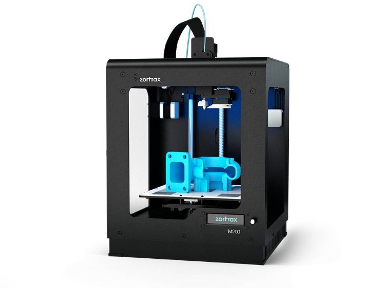
Key Takeaways
- Three-dimensional (3D) printing is an additive manufacturing process in which a physical object is created from a digital design by printing thin layers of material and then fusing them together.
- Some industries, such as hearing aids manufacturers, airline manufacturers, and car manufacturers, use 3D printing to create prototypes and mass produce their products using custom scans.
- While it is currently too slow to be used in mass production, 3D printing technology is still evolving and has the potential to massively disrupt both the manufacturing logistics and inventory management industries.
Understanding 3D Printing
Since it was introduced, 3D printing technology has already increased manufacturing productivity. In the long-term, it has the potential to massively disrupt both the manufacturing, logistics, and inventory management industries, especially if it can be successfully incorporated into mass production processes.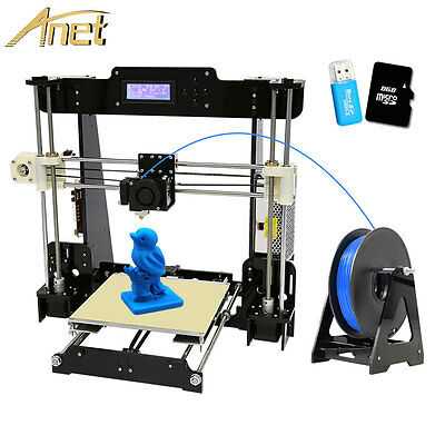
Currently, 3D printing speeds are too slow to be used in mass production. However, the technology has been used to reduce the lead time in the development of prototypes of parts and devices, and the tooling needed to make them. This is hugely beneficial to small-scale manufacturers because it reduces their costs and the time to market, that is, the amount of time from a product being conceived until its being available for sale.
3D printing can create intricate and complex shapes using less material than subtractive manufacturing processes, such as drilling, welding, injection molding, and other processes. Making prototypes faster, easier, and cheaper allows for more innovation, experimentation, and product-based startups.
Industrial Uses
Car and aircraft manufacturers have taken the lead in 3D manufacturing, using the technology to transform unibody and fuselage design and production, and powertrain design and production. Boeing is using 3D-printed titanium parts in the construction of its 787 Dreamliner airliner. In 2017, General Electric created a helicopter engine with 16 parts instead of 900–an indication of how big an impact 3D printing could potentially have on supply chains.
In medical sciences, 3D printing is being used to customize implants. In the future, organs and body parts may be created using 3D printing techniques. In the fashion world, Nike, Adidas, and New Balance are using 3D printing to create their shoes. In the construction industry, companies around the world are making breakthroughs in 3D printing of the materials need to build homes. Using layers of concrete, homes can be built in 24 hours, which are stronger than regular cinder blocks and cost a fraction of the price.
In the manufacturing of hearing aids, 3D printing is now customary. The use of 3D printing accelerates the process of manufacturing and enables manufacturers to make custom hearing aids. Audiologists can use 3D scanners to create a custom prototype using reference points from the scan. Manufacturers can feed the scan into a 3D printing machine and after fine-tuning the materials and the ear shapes, print the entire hearing aids.
Article Sources
Investopedia requires writers to use primary sources to support their work. These include white papers, government data, original reporting, and interviews with industry experts. We also reference original research from other reputable publishers where appropriate. You can learn more about the standards we follow in producing accurate, unbiased content in our editorial policy.
Norsk Titanium. "Norsk Titanium to Deliver the World’s First FAA-Approved, 3D-Printed, Structural Titanium Components to Boeing." Accessed Aug. 23, 2021.
General Electric. "An Epiphany Of Disruption: GE Additive Chief Explains How 3D Printing Will Upend Manufacturing." Accessed Aug. 23, 2021.
Nike. "Nike Flyprint is the First Performance 3D Printed Textile Upper." Accessed Aug. 23, 2021.
Adidas. "4DFWD: Data-Driven 3D Printed Performance Technology Designed to Move You Forward." Accessed Aug.23, 2021.
New Balance.
 "New Balance Launches a Premium 3D Printing Platform." Accessed Aug. 23, 2021.
Sonova. "3D Printing Technology for Improved Hearing." Accessed Aug. 23, 2021.
What is 3D Printing? - Technology Definition and Types
3D printing, also known as additive manufacturing, is a method of creating a three dimensional object layer-by-layer using a computer created design.
3D printing is an additive process whereby layers of material are built up to create a 3D part. This is the opposite of subtractive manufacturing processes, where a final design is cut from a larger block of material. As a result, 3D printing creates less material wastage.
This article is one of a series of TWI frequently asked questions (FAQs).
3D printing is also perfectly suited to the creation of complex, bespoke items, making it ideal for rapid prototyping.
Contents
- What materials can be used?
- History
- Technologies
- Process types
- How long does it take?
- Advantages and disadvantages
- What is an STL file?
- Industries
- Services
- FAQs
TWI
TWI is an Industrial Membership based organisation. TWI's experts can provide your company with an extension to your own resources. Our experts are dedicated to helping industry improve safety, quality, efficiency and profitability in all aspects of materials joining technology. Industrial Membership of TWI currently extends to over 600 companies worldwide, embracing all industrial sectors.
You can find out more by contacting us, below:
There are a variety of 3D printing materials, including thermoplastics such as acrylonitrile butadiene styrene (ABS), metals (including powders), resins and ceramics.
Who Invented 3D Printing?
The earliest 3D printing manufacturing equipment was developed by Hideo Kodama of the Nagoya Municipal Industrial Research Institute, when he invented two additive methods for fabricating 3D models.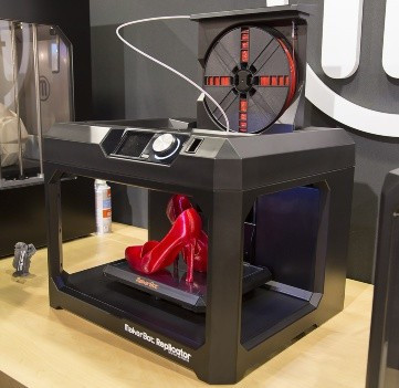
When was 3D Printing Invented?
Building on Ralf Baker's work in the 1920s for making decorative articles (patent US423647A), Hideo Kodama's early work in laser cured resin rapid prototyping was completed in 1981. His invention was expanded upon over the next three decades, with the introduction of stereolithography in 1984. Chuck Hull of 3D Systems invented the first 3D printer in 1987, which used the stereolithography process. This was followed by developments such as selective laser sintering and selective laser melting, among others. Other expensive 3D printing systems were developed in the 1990s-2000s, although the cost of these dropped dramatically when the patents expired in 2009, opening up the technology for more users.
There are three broad types of 3D printing technology; sintering, melting, and stereolithography.
- Sintering is a technology where the material is heated, but not to the point of melting, to create high resolution items.
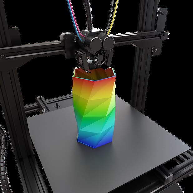 Metal powder is used for direct metal laser sintering while thermoplastic powders are used for selective laser sintering.
 - Melting methods of 3D printing include powder bed fusion, electron beam melting and direct energy deposition, these use lasers, electric arcs or electron beams to print objects by melting the materials together at high temperatures.
- Stereolithography utilises photopolymerization to create parts. This technology uses the correct light source to interact with the material in a selective manner to cure and solidify a cross section of the object in thin layers.
Types of 3D printing
3D printing, also known as additive manufacturing, processes have been categorised into seven groups by ISO/ASTM 52900 additive manufacturing - general principles - terminology. All forms of 3D printing fall into one of the following types:
- Binder Jetting
- Direct Energy Deposition
- Material Extrusion
- Material Jetting
- Powder Bed Fusion
- Sheet Lamination
- VAT Polymerization
Binder Jetting
Binder jetting deposits a thin layer of powered material, for example metal, polymer sand or ceramic, onto the build platform, after which drops of adhesive are deposited by a print head to bind the particles together.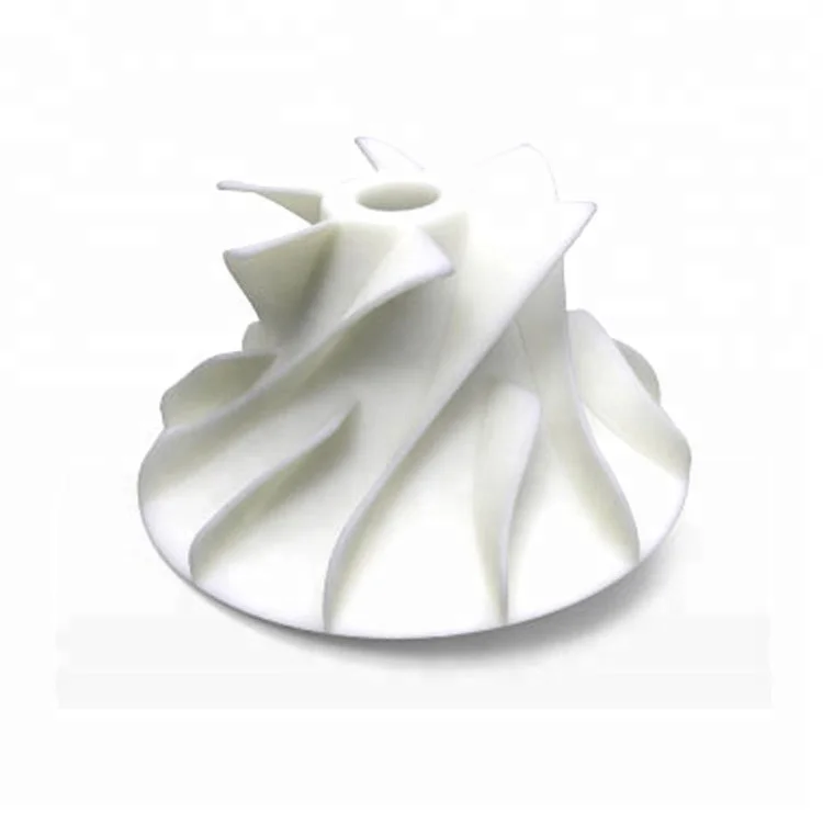 This builds the part layer by layer and once this is complete post processing may be necessary to finish the build. As examples of post processing, metal parts may be thermally sintered or infiltrated with a low melting point metal such as bronze, while full-colour polymer or ceramic parts may be saturated with cyanoacrylate adhesive.
Binder jetting can be used for a variety of applications including 3D metal printing, full colour prototypes and large scale ceramic moulds.
Direct Energy Deposition
Direct energy depositioning uses focussed thermal energy such as an electric arc, laser or electron beam to fuse wire or powder feedstock as it is deposited. The process is traversed horizontally to build a layer, and layers are stacked vertically to create a part.
This process can be used with a variety of materials, including metals, ceramics and polymers.
Material Extrusion
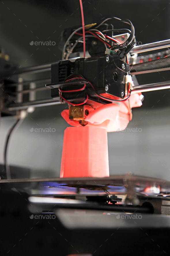
Material extrusion or fused deposition modelling (FDM) uses a spool of filament which is fed to an extrusion head with a heated nozzle. The extrusion head heats, softens and lays down the heated material at set locations, where it cools to create a layer of material, the build platform then moves down ready for the next layer.
This process is cost-effective and has short lead times but also has a low dimensional accuracy and often requires post processing to create a smooth finish. This process also tends to create anisotropic parts, meaning that they are weaker in one direction and therefore unsuitable for critical applications.
Material Jetting
Material jetting works in a similar manner to inkjet printing except, rather than laying down ink on a page, this process deposits layers of liquid material from one or more print heads. The layers are then cured before the process begins again for the next layer. Material jetting requires the use of support structures but these can be made from a water-soluble material that can be washed away once the build is complete.
A precise process, material jetting is one of the most expensive 3D printing methods, and the parts tend to be brittle and will degrade over time.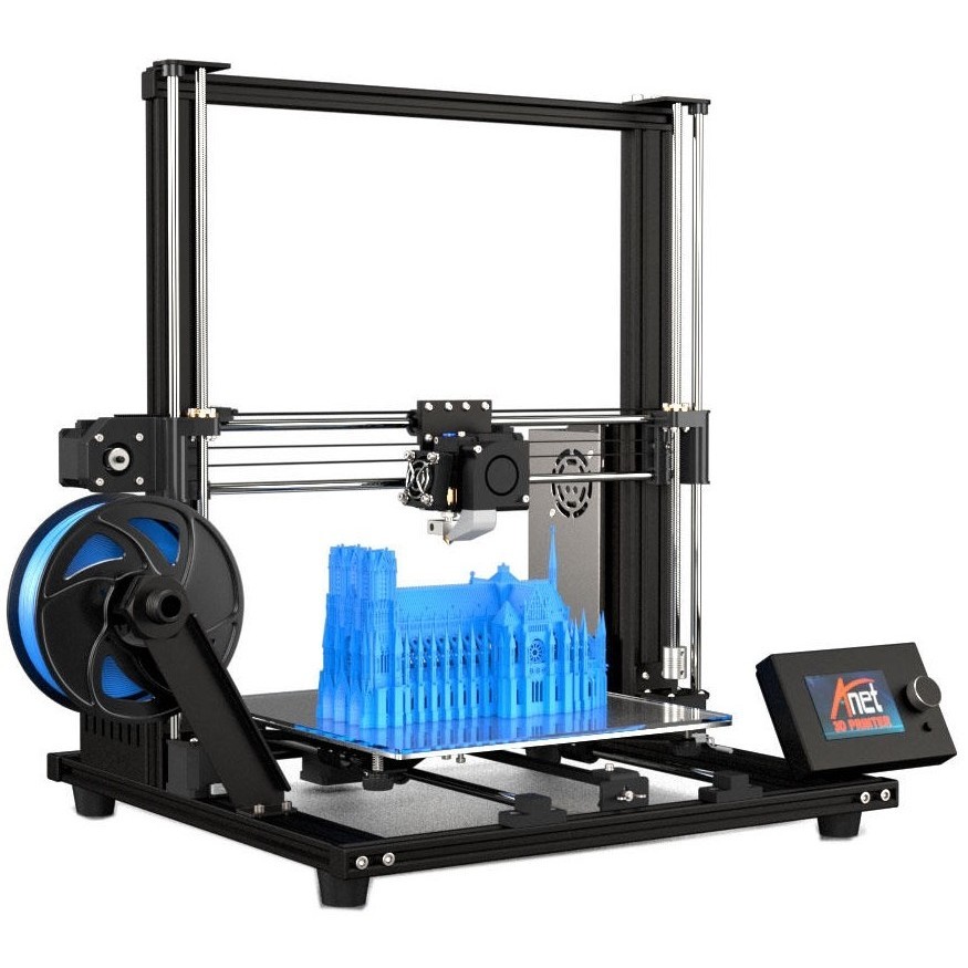 However, this process allows for the creation of full-colour parts in a variety of materials.
Powder Bed Fusion
Powder bed fusion (PBF) is a process in which thermal energy (such as a laser or electron beam) selectively fuses areas of a powder bed to form layer, and layers are built upon each other to create a part. One thing to note is that PBF covers both sintering and melting processes. The basic method of operation of all powder bed systems is the same: a recoating blade or roller deposits a thin layer of the powder onto the build platform, the powder bed surface is then scanned with a heat source which selectively heats the particles to bind them together. Once a layer or cross-section has been scanned by the heat source, the platform moves down to allow the process to begin again on the next layer. The final result is a volume containing one or more fused parts surrounded by unaffected powder. When the build is complete, the bed is fully raised to allow the parts to be removed from the unaffected powder and any required post processing to begin.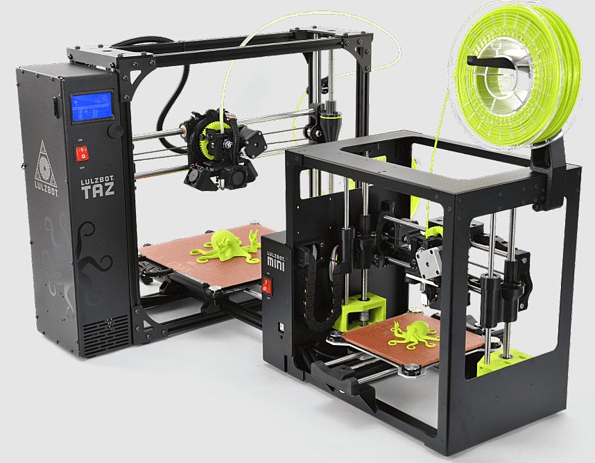
Selective laser sintering (SLS) is often used for manufacture of polymer parts and is good for prototypes or functional parts due to the properties produced, while the lack of support structures (the powder bed acts as a support) allows for the creation of pieces with complex geometries. The parts produced may have a grainy surface and inner porosity, meaning there is often a need for post processing.
Direct metal laser sintering (DMLS), selective laser melting (SLM) and electron beam powder bed fusion (EBPBF) are similar to SLS, except these processes create parts from metal, using a laser to bond powder particles together layer-by-layer. While SLM fully melts the metal particles, DMLS only heats them to the point of fusion whereby they join on a molecular level. Both SLM and DMLS require support structures due to the high heat inputs required by the process. These support structures are then removed in post processing ether manually or via CNC machining. Finally, the parts may be thermally treated to remove residual stresses.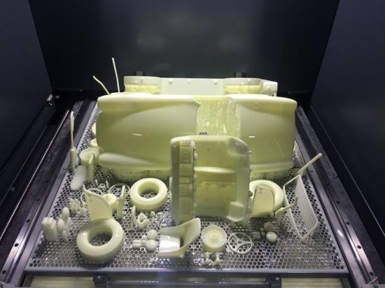
Both DMLS and SLM produce parts with excellent physical properties - often stronger than the conventional metal itself, and good surface finishes. They can be used with metal superalloys and sometimes ceramics which are difficult to process by other means. However, these processes can be expensive and the size of the produced parts is limited by the volume of the 3D printing system used.
Sheet Lamination
Sheet lamination can be split into two different technologies, laminated object manufacturing (LOM) and ultrasonic additive manufacturing (UAM). LOM uses alternate layers of material and adhesive to create items with visual and aesthetic appeal, while UAM joins thin sheets of metal via ultrasonic welding. UAM is a low temperature, low energy process that can be used with aluminium, stainless steel and titanium.
VAT Photopolymerization
VAT photopolymerization can be broken down into two techniques; stereolithography (SLA) and digital light processing (DLP).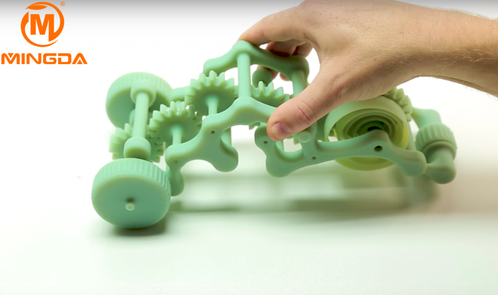 These processes both create parts layer-by-layer through the use of a light to selectively cure liquid resin in a vat. SLA uses a single point laser or UV source for the curing process, while DLP flashes a single image of each full layer onto the surface of the vat. Parts need to be cleaned of excess resin after printing and then exposed to a light source to improve the strength of the pieces. Any support structures will also need to be removed and additional post-processing can be used to create a higher quality finish.
Ideal for parts with a high level of dimensional accuracy, these processes can create intricate details with a smooth finish, making them perfect for prototype production. However, as the parts are more brittle than fused deposition modelling (FDM) they are less suited to functional prototypes. Also, these parts are not suitable for outdoor use as the colour and mechanical properties may degrade when exposed to UV light from the sun. The required support structures can also leave blemishes that need post processing to remove.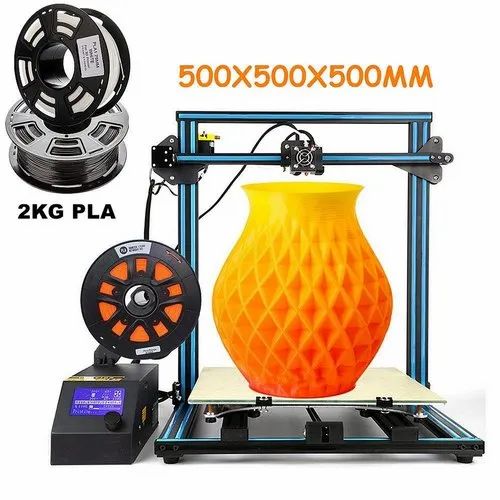
The printing time depends on a number of factors, including the size of the part and the settings used for printing. The quality of the finished part is also important when determining printing time as higher quality items take longer to produce. 3D printing can take anything from a few minutes to several hours or days - speed, resolution and the volume of material are all important factors here.
The advantages of 3D printing include:
- Bespoke, cost-effective creation of complex geometries:
This technology allows for the easy creation of bespoke geometric parts where added complexity comes at no extra cost. In some instances, 3D printing is cheaper than subtractive production methods as no extra material is used. - Affordable start-up costs:
Since no moulds are required, the costs associated with this manufacturing process are relatively low. The cost of a part is directly related to the amount of material used, the time taken to build the part and any post processing that may be required.
 - Completely customisable:
Because the process is based upon computer aided designs (CAD), any product alterations are easy to make without impacting the manufacturing cost. - Ideal for rapid prototyping:
Because the technology allows for small batches and in-house production, this process is ideal for prototyping, which means that products can be created faster than with more traditional manufacturing techniques, and without the reliance on external supply chains. - Allows for the creation of parts with specific properties:
Although plastics and metals are the most common materials used in 3D printing, there is also scope for creating parts from specially tailored materials with desired properties. So, for example, parts can be created with high heat resistance, water repellency or higher strengths for specific applications.
The disadvantages of 3D printing include:
- Can have a lower strength than with traditional manufacture:
While some parts, such as those made from metal, have excellent mechanical properties, many other 3D printed parts are more brittle than those created by traditional manufacturing techniques. This is because the parts are built up layer-by-layer, which reduces the strength by between 10 and 50%. - Increased cost at high volume:
Large production runs are more expensive with 3D printing as economies of scale do not impact this process as they do with other traditional methods. Estimates suggest that when making a direct comparison for identical parts, 3D printing is less cost effective than CNC machining or injection moulding in excess of 100 units, provided the parts can be manufactured by conventional means. - Limitations in accuracy:
The accuracy of a printed part depends on the type of machine and/or process used. Some desktop printers have lower tolerances than other printers, meaning that the final parts may slightly differ from the designs. While this can be fixed with post-processing, it must be considered that 3D printed parts may not always be exact.
 - Post-processing requirements:
Most 3D printed parts require some form of post-processing. This may be sanding or smoothing to create a required finish, the removal of support struts which allow the materials to be built up into the designated shape, heat treatment to achieve specific material properties or final machining.
An STL file is a simple, portable format used by computer aided design (CAD) systems to define the solid geometry for 3D printable parts. An STL file provides the input information for 3D printing by modelling the surfaces of the object as triangles that share edges and vertices with other neighbouring triangles for the build platform. The resolution of the STL file impacts the quality of the 3D printed parts - if the file resolution is too high the triangle may overlap, if it is too low the model will have gaps, making it unprintable. Many 3D printers require an STL file to print from, however these files can be created in most CAD programs.
Due to the versatility of the process, 3D printing has applications across a range of industries, for example:
Aerospace
3D printing is used across the aerospace (and astrospace) industry due to the ability to create light, yet geometrically complex parts, such as blisks. Rather than building a part from several components, 3D printing allows for an item to be created as one whole component, reducing lead times and material wastage.
Automotive
The automotive industry has embraced 3D printing due to the inherent weight and cost reductions. It also allows for rapid prototyping of new or bespoke parts for test or small-scale manufacture. So, for example, if a particular part is no longer available, it can be produced as part of a small, bespoke run, including the manufacture of spare parts. Alternatively, items or fixtures can be printed overnight and are ready for testing ahead of a larger manufacturing run.
Medical
The medical sector has found uses for 3D printing in the creation of made-to-measure implants and devices. For example, hearing aids can be created quickly from a digital file that is matched to a scan of the patient's body. 3D printing can also dramatically reduce costs and production times.
Rail
The rail industry has found a number of applications for 3D printing, including the creation of customised parts, such as arm rests for drivers and housing covers for train couplings. Bespoke parts are just one application for the rail industry, which has also used the process to repair worn rails.
Robotics
The speed of manufacture, design freedom, and ease of design customisation make 3D printing perfectly suited to the robotics industry. This includes work to create bespoke exoskeletons and agile robots with improved agility and efficiency.
TWI has one of the most definitive ranges of 3D Printing services, including selective laser melting, laser deposition, wire and arc additive manufacturing, wire and electron beam additive manufacturing and EB powder bed fusion small-scale prototyping, and more.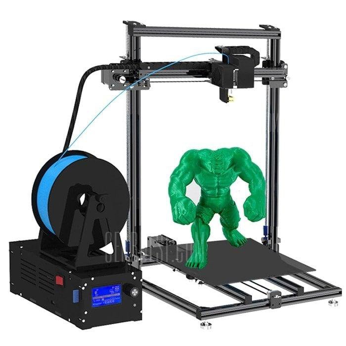
Additive Manufacturing
TWI provides companies with support covering every aspect of metal additive manufacturing (AM), from simple feasibility and fabrication projects to full adoption and integration of metal AM systems.
Laser Metal Deposition
TWI has been developing LMD technology for the last ten years. For full details of our capabilities in this area, and to find out more about the process and the benefits it can bring to your business.
Selective Laser Melting
TWI has been developing selective laser melting technology for the last decade. Find out full details of our capabilities in this area and the benefits it can bring to your business.
Can 3D Printing be used for Mass Production?
While there have been great advances in 3D printing, it still struggles to match other manufacturing techniques for high volume production. Techniques such as injection moulding allow for much faster mass production of parts.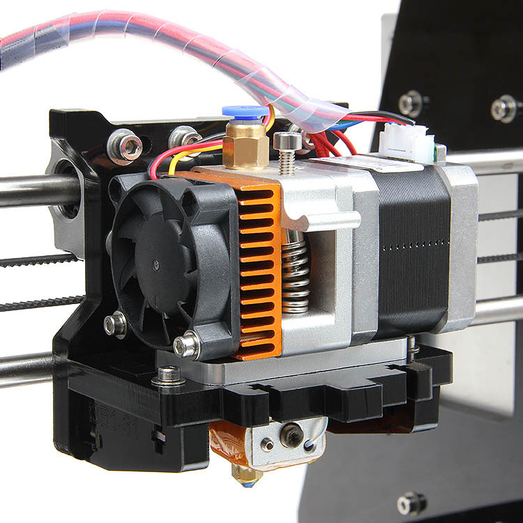
Where is 3D Printing Heading in the Future?
As 3D printing technology continues to improve it could democratise the manufacture of goods. With printers becoming faster, they will be able to work on larger scale production projects, while lowering the cost of 3D printing will help its use spread outside of industrial uses and into homes, schools and other settings.
Which 3D Printing Material is most Flexible?
Thermoplastic polyurethane (TPU) is commonly deemed to be the most flexible material available to the 3D printing industry. TPU possesses bendable and stretchy characteristics that many other filaments do not have.
Which 3D Printing Material is the Strongest?
Polycarbonate is seen as the strongest 3D printing material, with a tensile strength of 9,800 psi, compared to nylon, for example, with just 7,000 psi.
Why is 3D Printing Important?
3D printing is important for the many benefits it brings. It allows users to produce items that have geometries which are difficult or impossible for traditional methods to produce.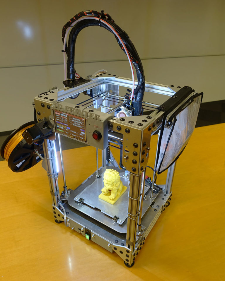 It also allows users with a limited experience to edit designs and create bespoke, customised parts. On-demand 3D printing also saves on tooling costs and provides an advanced time-to-market. 3D printing is important for industries such as aerospace, where it can create lightweight yet complex parts, offering weight saving, the associated fuel reductions and a better environmental impact as a result. It is also important for the creation of prototypes that can advance industry.
Will 3D Printing Replace Traditional Manufacturing?
3D printing has the capability to disrupt traditional manufacturing through the democratisation of production along with the production of moulds, tools and other bespoke parts. However, challenges around mass production mean that 3D printing is unlikely to replace traditional manufacturing where high volume production of comparatively simple parts is required.
Are 3D Printing Fumes Dangerous?
3D printing fumes can be dangerous to your health as the process produces toxic filament fumes. These emissions are produced as the plastic filaments are melted to create the product layer-by-layer. However, correct procedures such as ensuring sufficient ventilation or using extractors can solve this issue.
Related Frequently Asked Question (FAQs)
What are the Pros and Cons of 3D Printing?
The demand is growing due to some of the revolutionary benefits that it can provide. Like almost all technologies it has its own drawbacks that need considering.
How Long Does 3D Printing Take?
There are several factors that determine the time it takes to 3D print a part. These include the size, height, complexity and the printing technology used.
Can 3D Printing Use Metal?
Yes, it is possible to 3D print items from metal. There are several types of process which fall under the heading of metal additive manufacturing.
What is Additive Manufacturing?
Additive manufacturing (AM) is a computer controlled process that creates three dimensional objects by depositing materials, usually in layers.
How to create models that are larger than the print volume of a 3D printer
Don't have a large format 3D printer yet? When evaluating the capabilities of a compact desktop 3D printer, do not limit yourself to print volume. Many objects, like your smartphone or a bridge over a river, are made up of many individual components. Therefore, splitting the model into smaller parts that can be aligned after printing is a great solution for 3D printing large objects that do not fit on the platform.
Also, splitting the model can be a great way to get a high quality result, even if the whole model fits on the platform. This makes sense when multiple or opposing surfaces must be free from support structures, when the model has complex ledges, or contains cavities where liquid polymer can remain.
3D printing of various parts opens up new possibilities, for example, the creation of prefabricated structures from various materials or the combination of rigid and flexible parts to simulate the overmolding method.
When choosing a gluing method, it is necessary first of all to take into account the required degree of strength of the glued joints, which depends on the purpose of the models:
-
chemical: use adhesive on artwork, scale models, and complex shapes that are not intended for functional use and should not be impacted;
-
Mechanical: Provide threaded holes or sockets for attaching parts that require a secure mechanical connection, or repeatedly detaching and attaching components as needed.
This tutorial focuses on building large, prefabricated 3D stereolithographic (SLA) printed models with chemically bonded components. Read on to learn all the steps in this process, from model separation to post-processing for a professional finish.
Formlabs Form 3L is the first affordable, easy-to-use large format 3D printer optimized for reliable production of industrial-quality models. The Form 3L stereolithographic 3D printer features a huge print volume of 30 x 33. 5 x 20 cm and unrivaled cost-effectiveness.
Meet the Form 3L
We recommend two ways to separate models: adding features to the design that will allow the parts to fit together, or separating the model with straight lines, which will require them to fit together properly during the bonding process.
Regardless of which method you choose, if you have a lot of parts, it's helpful to add a unique identifier (letters/numbers) for each one to make assembly easier.
Use CAD software to split a 3D model and add basic centering components such as slots, pins, slots, notches, and tabs, or more complex features such as dovetails and slots to match model folds.
Adding centering components to the design makes it easier to assemble parts.
Ideally, these components should make it easier to align and assemble parts, but can cause problems if they differ even slightly from your 3D models, preventing perfect centering. Therefore, it is best to use centering components only when the printer can print parts with accurate dimensions that are not subject to deformation.
Splitting a 3D model along straight lines requires less effort than adding components to center it. With this separation method, there are also fewer problems if the parts are slightly deformed or differ in size.
Adding IDs for each part makes the assembly process easier.
On the other hand, parts separated by straight lines can be time consuming to assemble, as each part must be manually centered and ensured that they all remain in the correct position until the adhesive is completely dry.
By default, when printing on a stereolithographic 3D printer, solid models without voids are obtained. Depending on the design, different requirements may apply to the manufacture of large items. In such cases, 3D printing the outer shell or converting the structure into a hollow is a great way to save a lot of material and time. When printing hollow models on a stereolithographic 3D printer, be sure to add ventilation holes to avoid creating cavities filled with air and pressurized resin.
SAMPLE PART
Experience Formlabs print quality firsthand. We will send a free sample of the printed model directly to your office.
Request a free print sample
Converting a model design to a hollow saves a lot of time and material because the printer only needs to print the outer shell.
Learn more about how to save materials and time by hollowing out 3D models.
Depending on the size of the details and the purpose of the model, we recommend three mounting methods:
| Epoxy glue (5-30 min) | cyanoacrylate (CCA, Supercollah) | Resin | ||||
|---|---|---|---|---|---|---|
| Square. | Large | Small/Medium | Small | |||
| Paintable | Yes | Yes | Yes | 9006 70072Medium | Low | Low |
For large parts and maximum adhesion, use 5-30 minute dry epoxy. It takes longer to dry than other adhesives, allowing you to fit large 3D printed parts but slows down the assembly process. Most 5-minute epoxy adhesives stop changing shape in as little as five minutes and cure by about 75% in less than an hour.
For large parts and maximum adhesion we recommend using epoxy adhesive.
The next option is cyanoacrylate (CA or superglue), which quickly forms a strong bond, ideal for small to medium sized parts. Thoroughly clean the part before applying CA to the surface, because contaminants adversely affect the quality of the connection. CA has a moderate impact strength, but is not recommended for models that require high strength.
For small models, you can simply use liquid resin from a stereolithographic 3D printer. Pour a small amount of resin into a tray from a bottle or cartridge, pick it up with a pipette or syringe, and place it on the surface to be bonded. Connect the parts and wipe off excess resin that may spill around the edges.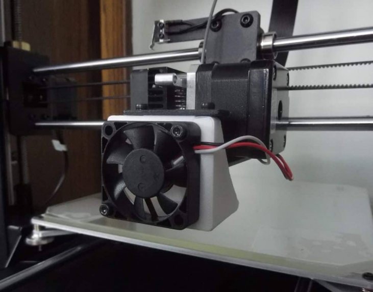 Aim a 5mW (405µm wavelength) UV laser pointer at the contact area to cure the resin and bond the parts.
This method produces a chemical bond similar to 3D stereolithography printing, but is only suitable for bonding small surfaces as a low power light pointer cannot penetrate the model deep enough to create a strong bond.
Note. Protective equipment must be worn when working with polymers, including proper eye protection and gloves.
Download PDF
Don't have time to read the article now? Download it in PDF format.
Download as PDF
After assembling the model, it's time to move on to post-processing. This step includes geometric correction of the model to provide a smooth surface that matches the original 3D model, and aesthetic finishing to obtain a uniformly colored surface.
Depending on the precision of the printer and the size of the printed parts, there will almost always be slight voids or mismatches at the contact points. Automotive sealant (e.g. Bondo 907) adheres well to polymers, therefore, to eliminate such inconsistencies, it is recommended to apply it in a thin layer on the surface. Lightly sand the surface after each coat has dried to bring the model to its final shape.
Sealing models with automotive sealant (red area in image) will help eliminate small gaps and inconsistencies between parts.
Sanding helps remove traces of support structures and remaining inconsistencies in the model. Gently start sanding the surface with 150-grit sandpaper to remove traces of support structures and smooth edges where parts meet. Once the surface is smooth, sand it wet using 320 grit sandpaper to remove any remaining layer lines. Sand the surface in random motions so as not to leave marks. In most cases, these two methods will produce a fairly smooth surface, but you can continue to increase the grit of the sandpaper up to 2 times and, after wetting it, sand the entire model until the surface is reasonably smooth.
Power sanding is great for large flat surfaces, but can ruin fine details. Grinding of small models is recommended to be done by hand, and for large ones, a combination of manual and mechanical grinding is recommended.
Machining large parts with mechanical and manual grinding saves a lot of time. Power sanding is great for large, flat surfaces, but can ruin the fine details, sharp corners, and subtle contours that are typical of stereolithography. As a result of mechanical grinding, a lot of dust is also generated, so before starting processing, it is necessary to prepare the working area.
Note. The use of power tools requires full attention and the use of protective equipment. The surface can be damaged very quickly without even realizing it, just by leaving the sander without moving.
When finished sanding the model, rinse it in soapy water to remove dust and debris and dry thoroughly before proceeding to the last step.
The primer helps the paint adhere to the surface and can indicate areas where additional sanding is needed or removal of traces of supports that you may have missed. The Universal Matte Gray Plastic Primer shows these spots exceptionally well. For best results, apply it to the surface in several thin coats. Sand critical areas and reapply a thin coat of primer. Repeat this process until the entire surface of the model is level.
Note. Use protective equipment during priming and painting, including a respirator to protect against paint fumes.
All-purpose matt gray primer for plastics is exceptionally good at showing fine details and helping to identify areas that need to be sanded down.
Find out more about sanding and priming in our detailed guide.
When painting with multiple colors, protect the model with a temporary coat. First, plan the order in which you will paint the model, depending on the color, transparency, and size of the area of a particular color. Start with small details so that fewer of them can be protected when painting with the main color. Apply painter's tape to the edges and corners. To quickly cover large areas, attach sheets of paper to them. Ribbon guides (laser cut) can also be useful for creating straight lines, circles and complex shapes.
When it comes to masking, figuring out the correct order is your first priority. In our case, the parts were first painted silver and the sections that would remain silver on the final part were then covered with painter's tape to hide them from the next l
painting. In our case, we first painted the parts silver and put masking tape on the areas that should remain silver in the finished model so that they do not get paint of a different color.
As with primer, several thin coats of paint should be applied for optimal results rather than one thick coat. Most spray paints will achieve the best color in warm and slightly damp conditions in the absence of wind. In this case, you must always follow the manufacturer's recommendations, which can be given on the paint container or in the technical documentation.
Consider the time the paint needs to dry: Allow layers to settle before applying the same color and allow the paint to dry completely before applying a new color.
The area where we applied masking tape is still silver.
Become an expert in painting 3D models with our detailed guide
Already wondering what your finished model will look like?
"Sorry sir, that R2-D2 over there is in excellent condition and inexpensive."
Formlabs optics designer Adrien Tanner created this R2-D2 model from 105 parts printed on a Formlabs stereolithographic 3D printer. It even has working electronics borrowed from the Form 2 printer - a galvanometer drive for sound reproduction, a cartridge dispenser for lamps, and a Z-axis drive for dome rotation. 9The 0003
Form 3L is the first large-format 30 x 33.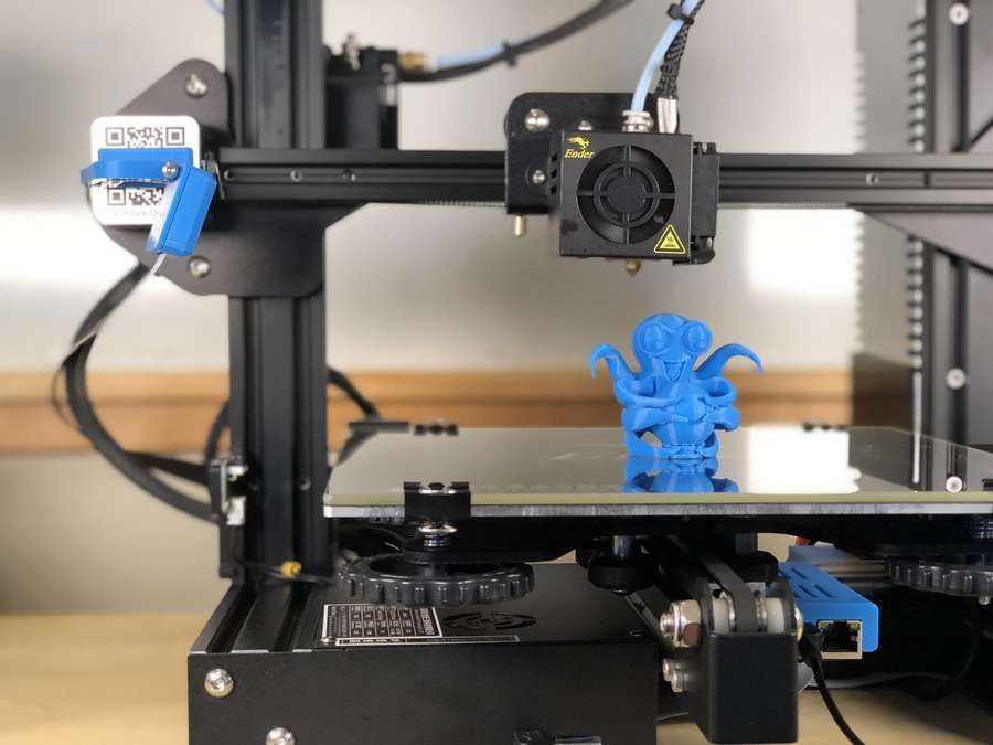 5 x 20 cm 3D printer for producing massive, industrial-quality models.
Reduce order processing time when outsourcing or manual work when assembling large-scale 3D models. Now you can print large 3D models in their entirety on the Form 3L, the first affordable large format SLA printer.
Want to see how stereolithographic parts work? Explore our resources to learn more about stereolithographic resins, or request a free sample to evaluate print quality for yourself.
Request a free print sample
Post-processing of 3D printed parts (PLA, ABS, SBS, PETG)
Table of Contents
- Remove Supports
- Remove Soluble Supports
- Sanding
- Cold welding
- Filling voids
- Polishing
- Priming and painting
- Pair smoothing
- Epoxy
- Metallization
Introduction
FDM technology is best suited for fast, low-budget prototyping. Layer lines are usually visible in FDM prints, so post-processing is essential if a smooth surface is to be achieved.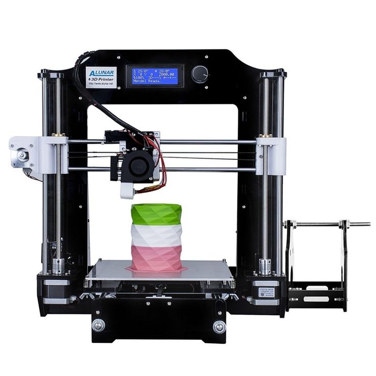 Some post-processing techniques can also make a print more durable by changing the degree of its elastic properties, density, structural and textural features.
In this article, we will discuss the most common post-processing techniques in FDM.
Post-processed FDM prints (left to right): cold welded, void filled, raw, sanded, polished, painted and epoxy coated. Photo 3dhubs.com
Removing supports
Removing supports is usually the first step in post-processing for any 3D printing technology that uses them. In general, props can be divided into two categories: standard and soluble. Unlike other post-processing methods discussed in this article, the removal of props is mandatory and does not result in improved surface quality.
Initial printout with props, poor prop removal, good prop removal. photo 3dhubs.com
Removal of standard props
Tools
- Nippers, needle nose pliers, tongs
- Toothbrush, brush
| Finishing | ★ ☆ ☆ ☆ ☆ |
| Approvals | ★ ★ ☆ ☆ ☆ |
| Speed | ★ ★ ★ ★ ☆ |
| Suitable for | all thermoplastics FDM |
Process
Normally, backups come off the printout without problems, and hard-to-reach places (such as holes or cavities) can be removed from the backup material with an old toothbrush.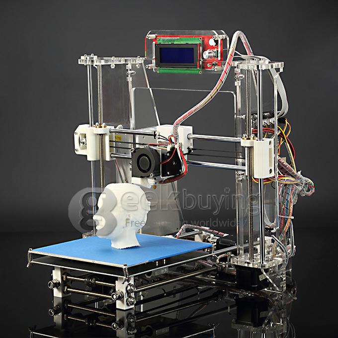 Proper placement of support structures and correct print orientation can significantly reduce the negative impact of supports on how the final printout will look.
Pros
- Does not change the overall geometry of the part.
- The process is very fast.
Cons
- Does not remove layer lines, scratches or other surface defects.
- If excess material or marks remain from the support structure, print accuracy and appearance suffer.
Soluble Support Removal
Instrumentation
- Solvent resistant container
- Thinner
- Ultrasonic cleaner (optional)
| Finishing | ★ ★ ★ ☆ ☆ |
| Approvals | ★ ★ ☆ ☆ ☆ |
| Speed | ★ ★ ★ ★ ☆ |
| Suitable for | all thermoplastics FDM |
Process
Soluble support standard materials are removed from the printout by immersing it in a reservoir of the appropriate solvent.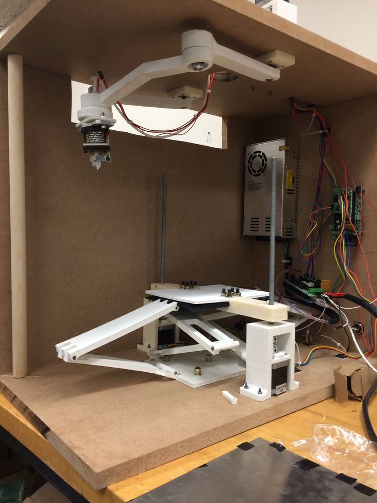 Supports are usually printed:
- HIPS (usually with ABS)
- PVA (usually with PLA)
A glass container like a preservation jar is fine. Any non-porous vessel is suitable for water treatment. To quickly remove props from HIPS/ABS printouts, you will need a solution of equal parts D-limonene and isopropyl alcohol. Many other support structure materials such as PVA (with PLA) dissolve in normal water.
Pro Tricks
Shorten the solution time by using an ultrasonic cleaner and changing the solvent as it becomes saturated. A warm (not hot) solution works faster - heating is useful if there is no cleaner.
Pluses
- Complex geometry is allowed for which the standard method of removing props is not possible.
- Smooth surface at the support points.
Cons
- Incorrect dissolution of the props can cause discoloration and skewed printouts.
- Does not remove layer lines, scratches or other surface imperfections.
- May cause small holes or holes if soluble material seeps into the object during printing.
Cleaning with a skin
SHID SHIP SHIP ABS ABS ABS PROBECTION
Instrumentation
- E END1 with grain
on 150, 220, 400, 600, 1000 and 2000 - Wiping cloth
- Toothbrush
- Soap
- Face mask
| Finishing | ★ ★ ★ ★ ☆ |
| Approvals | ★ ★ ★ ☆ ☆ |
| Speed | ★ ★ ☆ ☆ ☆ |
| Suitable for | all thermoplastics FDM |
Process
After the props have been removed or dissolved, sanding can be done to smooth the part and remove any obvious defects such as blots or marks from the props. Which sandpaper to start with depends on the thickness of the layer and the quality of the print: for layers of 200 microns or less, or for prints without blotches, you can start with sandpaper at P150. If there are blobs visible to the naked eye, or the object is printed with a layer thickness of 300 microns or more, stripping should begin with P100.
The process can be continued up to P2000 grit (one approach is to go to 220, then 400, 600, 1000 and finally 2000). Wet sanding is recommended from the very beginning to the very end - this will avoid excessive friction, which can lead to an increase in temperature and damage the object, as well as contaminate the sandpaper itself. Between sanding, the printout should be cleaned with a toothbrush and washed with soapy water, then wiped with a cloth to remove dust and prevent it from sticking together. Even P5000 can be sanded to achieve a smooth, shiny FDM part.
Pro Tricks
Always sand in small circular motions - evenly over the entire surface of the part. It may be tempting to sand perpendicular to the layers, or even parallel, but this can lead to gouges. If the part is discolored or has a lot of scratches after sanding, it can be heated a little to soften the surface and allow some defects to smooth out.
Pros
- An exceptionally smooth surface is obtained.
- Further post-processing (painting, polishing, smoothing and epoxy coating) is greatly facilitated.
Cons
- Not recommended for double or single shell parts as sanding may damage the printout.
- The process is difficult in the case of sophisticated surfaces and the presence of small details in the object.
- If the grinding is done too aggressively and too much material is removed, the appearance of the part may be affected. Acetone for ABS. Dichloromethane for PLA, ABS
- Sponge applicator
| Finishing | ★ ★ ☆ ☆ ☆ |
| Approvals | ★ ★ ☆ ☆ ☆ |
| Speed | ★ ★ ★ ★ ★ |
| Suitable for | all thermoplastics FDM |
Process
If the size of the object exceeds the capacity of the printer, the object is printed in parts and then assembled. In the case of PLA and some other materials, assembly can be done with Dichloromethane or a suitable adhesive (the choice of adhesive depends on the plastic). In the case of ABS, it is possible to "weld" with acetone. The mating surfaces should be slightly moistened with acetone and squeezed tightly or clamped and held until most of the acetone has evaporated. So the parts will be held together by chemical bonds.
Pro Tricks
Increasing the surface area of the acetone contact increases bond strength. Tongue-and-groove to help.
Pros
- Acetone does not change surface color as much as most adhesives.
- After drying, the compound acquires the properties of ABS, which makes further processing easier and more uniform.
Cons
- Cold "welding" acetone on ABS parts is not as strong as if the part were printed as a whole.
- Excessive use of acetone can dissolve the part and affect final appearance and tolerances.
Void Filler
Black ABS Print, Filled and Sanded
Tool Kit
- Epoxy (for small voids only)
- Automotive body filler (for large voids and joints)
- ABS filament and acetone (only for small voids in ABS printouts)
| Finishing | ★ ★ ☆ ☆ ☆ |
| Approvals | ★ ★ ★ ☆ ☆ |
| Speed | ★ ★ ★ ☆ ☆ |
| Suitable for | all thermoplastics FDM |
Process
Unusual voids may come out after the part has been ground or the soluble props have been dissolved. These voids are formed during printing when the layers are incomplete due to any restrictions on the trajectory of the print head, which is often inevitable. Small gaps and voids can be easily filled with epoxy and no additional treatment is required in this case. Larger gaps or voids left by assembling a multi-part object can be filled with automotive bodywork filler, but the printout will then need to be re-sanded. Putty works great, is easy to process with sandpaper and can be painted. Moreover, the parts connected by such a filler, or voids filled with it, turn out to be stronger than the original plastic.
Slots in ABS printouts can also be filled with ABS thinned with acetone, which reacts chemically with the ABS object and seeps into existing voids. It is recommended to make such a putty from 1 part ABS and 2 parts acetone, then it will not spoil the surface if used correctly.
Dichloromethane works on all plastics: ABS, PLA, HIPS, SBS, etc.
Epoxy is also useful if you want to make your 3D printed part more durable
Pros
- Epoxy filler is easy to sand and prime, resulting in an excellent surface for painting.

- ABS solution of the same filament will give the same color so nothing will be visible on the surface.
Cons
- Auto body filler or other polyester epoxy adhesive is opaque when dry and will leave discolored areas on the printout.
- Additional processing required to achieve a uniform surface.
- If the grinding is done too aggressively and too much material is removed, the appearance of the part may be affected.
Polished
PLA model, polished. Photo rigid.ink
Tool kit
- Plastic polishing compound
- Sandpaper for P2000
- Wiping cloth
- Toothbrush
- Polishing pad or microfibre cloth
| Finishing | ★ ★ ★ ★ ★ |
| Approvals | ★ ★ ★ ☆ ☆ |
| Speed | ★ ★ ☆ ☆ ☆ |
| Suitable for | all thermoplastics FDM |
Process
Once the part has been cleaned, a plastic polish can be applied to the part to give a standard ABS or PLA object a mirror finish. After the part has been sanded for 2000, it is necessary to remove dust from the printout with a cloth and rinse the printout under warm water using a toothbrush. When the object is completely dry, buff it on a buffing pad or microfiber cloth, adding a polishing compound as you go, such as polishing jewelry. They are designed specifically for plastics and synthetics and give a long-lasting shine. Other plastic polishes, such as those used to polish car headlights, also work well, but some of them contain chemicals that can damage the printout.
Pro Tricks
To polish small parts, place the polishing wheel on your Dremel (or other rotary tool such as a power drill). For larger and stronger parts, you can use a grinder, just make sure that the part does not stay in one place for too long, otherwise the plastic may melt from friction.
Pros
- The part is polished without solvents, which can distort it or change its tolerances.
- When properly ground and polished, a mirror-smooth surface is obtained, very similar to cast.
- Polishing and deburring plastics is extremely economical, making this a very cost-effective method of achieving a quality finish.
Cons
- If you want to achieve a mirror-smooth surface, the part must be carefully ground before polishing, which may affect tolerances.
- After polishing, the primer or paint no longer sticks.
Primer and paint
Gray PLA FDM print spray painted black. 3dhubs.com
Tools
- Wiping cloth
- Toothbrush
- 150, 220, 400 and 600 grit sandpaper
- Spray Primer for Plastics
- Finish paint
- Polishing sticks
- Polishing paper
- Masking tape (only if multiple colors are expected)
- Nitrile gloves and matching face mask
| Finishing | ★ ★ ★ ★ ★ |
| Approvals | ★ ★ ★ ☆ ☆ |
| Speed | ★ ☆ ☆ ☆ ☆ |
| Suitable for | all thermoplastics FDM |
Process
After the printout has been properly sanded (it is enough to reach P600 when painting), it can be primed. Aerosol plastic primer should be applied in two coats. This primer is intended for subsequent painting of models, provides an even coating and at the same time thin enough not to hide small elements. Thick primer, which is sold in hardware stores, can clump, and then you have to seriously work with sandpaper. Apply the first spray coat with short pressures from a distance of 15-20 cm from the object, trying to do it evenly. Let the primer dry and smooth out the unevenness with 600 grit sandpaper. Apply a second coat of spray with light, quick pressures, also very gently and evenly.
When the priming is completed, you can start painting. You can paint with artistic acrylic paints and brushes, but a spray gun will provide a smoother surface. Hardware store spray paints are thick and viscous and difficult to control, so use paints that are designed specifically for modeling. The primed surface must be sanded and polished (sanding and polishing sticks, which are used in nail salons, can be purchased online, they are great for our task), and then wiped with a cloth. The paint should be applied to the model in very thin layers, the first layers should be transparent. When the paint finish becomes opaque (usually 2-4 coats), let the model rest for 30 minutes to allow the paint to dry completely. Carefully polish the paint layer with manicure sticks, repeat the procedure for each of the colors (between each applied paint).
Separate parts of the model can be covered with masking tape so that the colors, if there are several, do not mix. When painting is complete, remove the masking tape and polish the object with polishing paper. Polishing paper, such as 3M or Zona, comes in a variety of grits and is a relatively new product. It is sold in packs in various online stores, and after processing with this paper, the ink layer or topcoat will literally shine - and nothing else can achieve this effect. Apply 1-2 coats of top coat to protect the paint and let it dry completely. The top coat is selected in accordance with the recommendations of the paint manufacturer. If the topcoat and paint are incompatible, it can render your entire painting job meaningless, so compatibility is very important here.
Pro Tips
When using spray paint, don't shake the can! It is important not to mix the pigment or primer with the propellant (propellant gas), which will cause bubbles to form in the spray. Instead, the can must be rotated for 2-3 minutes so that the mixing ball rolls like a pearl, and does not strum.
Pros
- An excellent result, if you take into account all the nuances of the process and practice.
- You can do anything with the final look of the object, no matter what material it is printed on.
Cons
- Primer and paint increase the volume of the model, which affects tolerances and can be a problem when it comes to a part of a larger object.
- High quality spray paint or spray gun increases costs.
Vapor smoothed
Vapor smoothed black ABS printed hemisphere
Tools
- Cleaning cloth
- Solvent resistant sealed container
- Thinner
- Paper towels
- Aluminum foil (or other solvent resistant material)
- Face mask and chemical resistant gloves
| Finishing | ★ ★ ★ ★ ☆ |
| Approvals | ★ ★ ☆ ☆ ☆ |
| Speed | ★ ★ ★ ☆ ☆ |
| Suitable for | all thermoplastics FDM |
Process
Line the bottom of the container with paper towels, if possible along the sides. It is critical that the vapors cannot damage the container and that the container itself is sealed. It is recommended to use a glass or metal container. Apply enough thinner to the paper towels so that they are wet but not soaked - this will also help them adhere better to the walls. Acetone is famous for its ability to smooth out ABS. PLA can be smoothed with a variety of other solvents (dichloromethane works well), but this plastic tends to be much harder to smooth than ABS. When working with any solvents, please follow the safety precautions for handling chemicals and always take appropriate precautions. Place a small "raft" of aluminum foil or other solvent-resistant material in the center of the paper towel-lined container. Place the printout on the "raft" (either side of your choice) and close the lid of the container. Steam polishing can take varying amounts of time, so check your printout periodically. To increase the speed of polishing, the container can be heated, but this must be done carefully so as not to cause an explosion.
When removing the printout from the container, try not to touch it in any way, leave it on the “raft”, take them out together. In all those places where the printout has come into contact with something, there will be defects, since the outer layer will be under-dissolved. Before working with it, let the printout completely “breathe” so that all solvent vapors have evaporated.
Many aerosols and/or solvent sprays are flammable or explosive and their vapors can be harmful to humans. Be extremely careful when heating solvents, always handle them and store them in a well ventilated area.
Pros
- Many small blotches, as well as a lot of layer lines, are smoothed out without additional processing.
- The printout surface becomes exceptionally smooth.
- The procedure is very fast and can be performed using commonly available materials.
Cons
- Doesn't "heal" gaps, doesn't completely hide layer lines.
- During the smoothing process, the outer layer of the printout dissolves, which greatly affects the tolerances.
- Negatively affects the strength of the printout due to changes in the properties of its material.
Immersion
PLA model immersed in dichloromethane. Photo 3dpt.ru
Tools
- Solvent resistant container
- Thinner
- Eye hook or cog
- Heavy wire for sculpture or landscaping
- Dryer or drying rack
- Face mask and chemical resistant gloves
| Finishing | ★ ★ ★ ★ ☆ |
| Approvals | ★ ☆ ☆ ☆ ☆ |
| Speed | ★ ★ ★ ★ ☆ |
| Suitable for | all thermoplastics FDM |
Process
Make sure the container you are using is wide and deep enough to completely submerge the printout in the solution.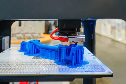 Fill the container with the appropriate amount of solvent - be careful not to splash. As with vapor smoothing, ABS dip smoothing can be done with acetone, which is easy to find in the store, and for PLA, dichloromethane can also work well with ABS, HIPS, SBS, PETG, and many other materials. PLA is quite resistant to solvent smoothing, so it may take several passes to achieve the desired result. Prepare the printout for dipping by screwing a hook or eye screw into it in an inconspicuous place. Pass the wire through the eyelet or wrap the wire around the screw so that the printout can be immersed in the solvent. If the wire is too thin, it will not be able to withstand the buoyant force on the printout, and it will be difficult to sink the object.
Once the printout is ready, use a wire to completely immerse it in the solvent for a few seconds. Remove the printout and hang it by the wire in a dryer or on a drying frame to allow the solvent to completely evaporate from the surface.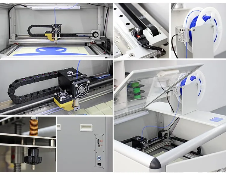 After ejection, the printout can be gently shaken to facilitate the drying process and ensure that no solvent has accumulated in the depressions.
Pro Tricks
If an opaque whitish coating appears on the printout after drying, this can be corrected by holding the object over a solvent bath for a while so that its vapor slightly dissolves the surface. This restores the original color of the printout and achieves a shiny outer layer.
Pros
- The printed surface is smoothed much faster than steam polishing.
- Significantly less fumes are generated than other solvent polishing methods, so this method is less hazardous.
Cons
- The surface is smoothed very aggressively, so you can forget about tolerances.
- Immersion for too long can result in complete deformation of the object and a significant change in material properties.
Epoxy
Black ABS printout, half epoxy coated, half uncoated
Toolbox
- 2-component epoxy06
- Sponge applicator
- Mixing container
- Sandpaper P1000 or finer
| Finishing | ★ ★ ★ ★ ☆ |
| Approvals | ★ ☆ ☆ ☆ ☆ |
| Speed | ★ ★ ★ ★ ☆ |
| Suitable for | all thermoplastics FDM |
Process
After the printout has been cleaned (preliminary cleaning gives the best end result), wipe it thoroughly with a cloth. Mix the resin and hardener in the proportion indicated in the instructions, accurately measuring all volumes. The curing process of epoxy resin is exothermic, so glass containers and containers made of materials with a low melting point should be avoided. It is recommended to use containers that are specifically designed for mixing epoxy resins. Incorrect ratio of resin and hardener can result in longer curing time or no curing at all and result in a permanently sticky substance. Mix the resin and thinner as directed in the instructions - carefully, in smooth movements to minimize the amount of air bubbles remaining inside the mixture. Very little epoxy is needed, and most of these resins only work for 10-15 minutes, so plan accordingly.
Apply the first coat of epoxy with a sponge applicator, being careful not to build up in crevices and small parts. When the printout is sufficiently coated, allow the resin to fully cure - as described in the instructions that came with it. One coat may be sufficient, but for optimum results it is best to lightly sand the printout with fine sandpaper (on P1000 and above) to eliminate any imperfections. Wipe off the dust with a cloth and, in the same way as before, apply a second layer of epoxy.
Pros
- A very thin coat of epoxy won't affect tolerance too much (unless the printout has been sanded too hard first).
- A protective shell is formed around the object.
Cons
- The layer lines will remain visible, they will only be covered by a smooth shell.
- If too much epoxy is used, it can flood parts and edges, and the surface can appear greasy.
Plating
FDM-printed structural element nickel-plated with Repliform RepliKote
Tools (for homework)
3
Solvent A galvanizing solution can be obtained by mixing a metal salt, acid and water, but if the proportions are inaccurate and the substances are of insufficient quality, one cannot count on a professional result. If you buy a ready-made solution (as in Midas kits), you can be sure that the problems with plating are not caused by the solution.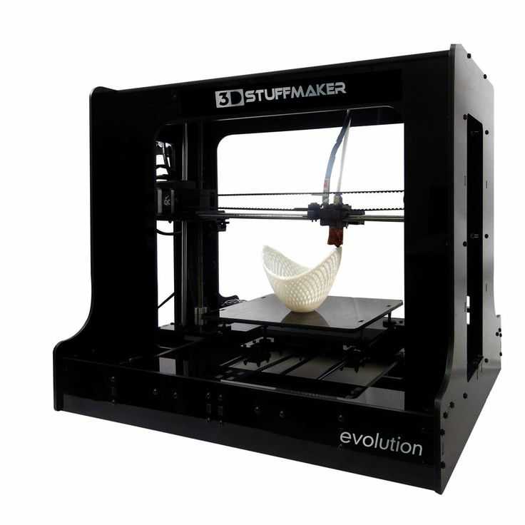
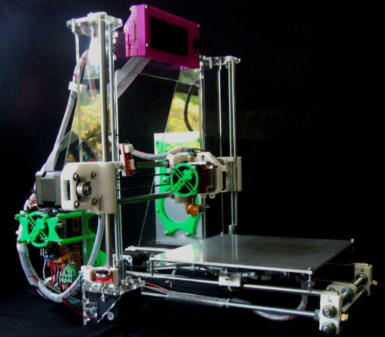
| Finishing | ★ ★ ★ ★ ☆ |
| Approvals | ★ ★ ★ ☆ ☆ |
| Speed | ★ ★ ★ ★ ☆ |
| Suitable for | all thermoplastics FDM |
Process
Electroplating can be carried out at home or in a professional workshop. To do everything right, you need to be well versed in the materials, in what is actually happening - and at home these opportunities are usually limited.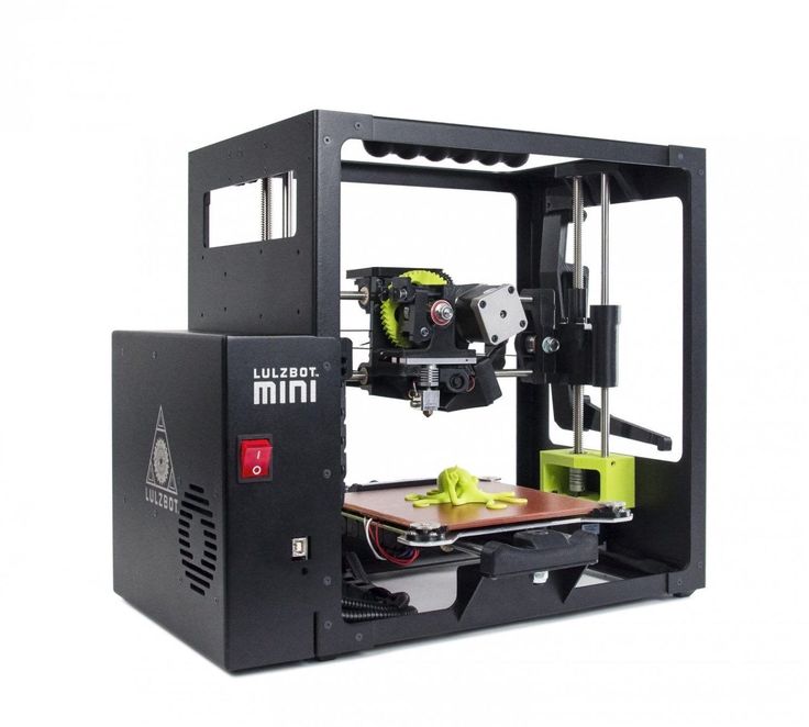 In order to achieve excellent surface quality and to have more plating options, including chrome plating, it is best to use the services of professional workshops. The copper galvanization process will be described below as an example.
At home, you can galvanize with copper or nickel, and this coating will then serve as the basis for galvanizing with other metals. It is critically important that the printout surface be as smooth as possible before it is galvanized. Any bumps and lines in the layers will be enhanced as a result of the process. Prepare the sanded and cleaned object for plating by coating the plastic with a thin coat of high quality conductive paint, or with a graphite and acetone solution for ABS printouts. Allow the conductive coating to dry completely, sand if necessary to ensure a smooth surface. At this stage, it is extremely important not to touch the printout with bare hands or to wear gloves, because sweat marks on the object will certainly affect the quality of the galvanization.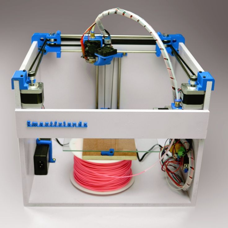
Insert a screw or eyelet in an inconspicuous place on the printout and connect it to the negative terminal of the rectifier. This will be the cathode. Connect the copper anode to the positive contact of the rectifier. Fill the container with enough copper plating solution so that the printout is completely covered with it. Immerse the anode in the container and turn on the power. After the rectifier is turned on, immerse the printout in the container, making sure that it does not touch the anode anywhere. Beware! When the object is already in the bath, the galvanization system is active, and contact with the solution, cathode or anode can be traumatic. Set the voltage on the rectifier to 1-3 Volts, and the process will go to full metallization. To speed things up, the voltage can be increased, but not more than 5 volts. When enough metal has deposited on the printout, simply turn off the power and dry the object with microfiber towels. When it's dry, varnish the object to protect it from corrosion.