3D printer circuit
3D-printed circuit boards: How they're made and why they matter
Once confined mainly to home-brew tinkering, circuit boards created via 3D printing are now practical for some manufactured products.
J.F. Brandon, BotFactory Inc.
In the past ten years, 3D Printing has gone from a niche prototyping tool to a process acceptable for mass production. Most of the recent hubbub has been about monolithic plastic and metals. But new materials and processes have appeared to help create 3D-printed PCBs that meet long-standing engineering problems.
If the history of electronics manufacturing could be summarized in one phase, it would be, “Shrinking everything to nothing to squeeze out something faster.” The push towards miniaturization has been driven by the inviolable laws of nature – faster devices that consume less power require shorter electrical paths.
However, the printed circuit board is an outlier in the electronics world. PCBs still use basic drilling and plating processes perfected 50 years ago. That is not to say that PCB manufacturing is trivial or antiquated. But the investment in new PCB manufacturing methods is a pittance compared to the hundreds of billions put into chip fabs by IC makers such as TMSC and AMD.
It is worth looking at the details of PCBs and their construction. The word ‘printed’ in printed-circuit board only describes half of the process – the silkscreen masks are the only part that is printed. A PCB is originally copper foil on a rigid fiberglass laminate which is selectively etched, drilled, and plated using a set of silkscreens and chemical baths to produce the final product.
Examples of inkjet-printed circuitry made with a BotFactory SV2 PCB printer.The sole purpose of the PCB is to reliably connect passive and active components and provide a reliable platform for integration or interactions with the rest of a product. For example, the PCB in the average computer keyboard connects electronic elements together, but it also must manage human interactions and provide a sound mechanical connection to the body of the product.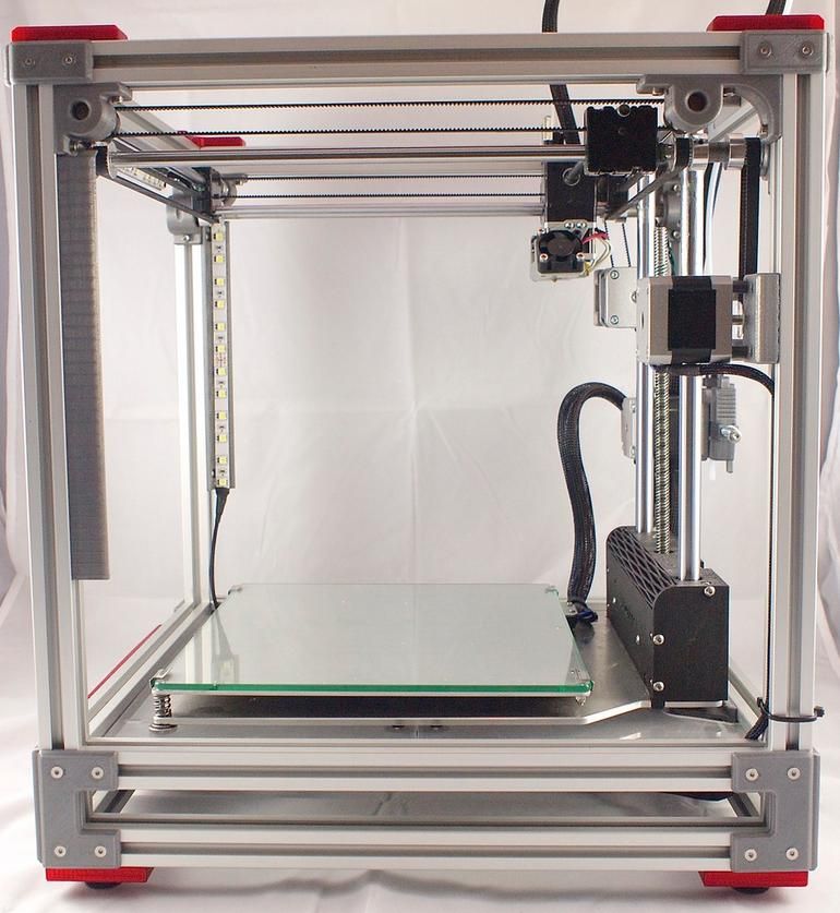 In addition, PCBs must be designed so they can easily be stenciled with reflow solder paste and integrated into industrial surface-mount pick-and-place lines. Optical inspection and flying-probe systems require PCBs that can be easily analyzed and binned for repair or discard automatically. All in all, modern PCBs can play a variety of roles within the end products in which they are found. So it is worth considering new manufacturing processes that can expand the capabilities of PCBs.
PCBs have thermal, electrical, geometric and mechanical requirements that go beyond what most materials for 3D printing can offer. For example, the average $500 3D printer that uses Fused Deposition Modeling (FDM) uses PLA, ABS and PETG which melt under the harsh gaze of any standard soldering station. Metal 3D printing techniques are designed to handle one material at one time. Yet PCBs require, at a bare minimum, a dense and conductive metal for conductors.
Three technical paths have appeared for PCB printing: inkjets, extrusion, and additive manufacturing (AM)-electroless plating.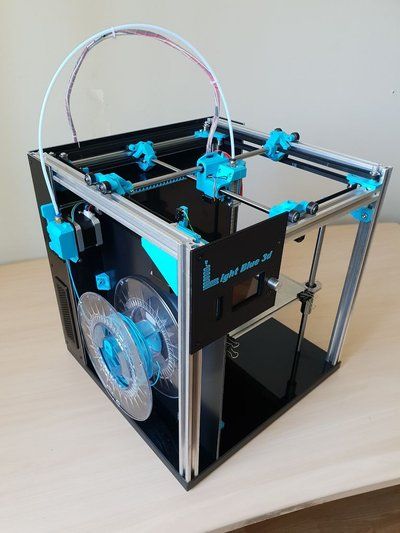 First consider ink-jetting. New nanoparticle and particle-free inks have allowed inkjet printing to go beyond CMYK inks and graphics. Inkjets can now lay down metal (overwhelmingly silver) inks in fine patterns on flexible materials. In combination with a polymer ink, it is possible to create PCBs with complex multilayer circuitry (blind and buried vias are trivial items) in only a few steps on a single machine.
The inherent advantage of creating PCBs layer-by-layer this way is that each layer can be tested and validated. The minimal level of processing simplifies the dispensing solder paste, part assembly, and testing for every layer. The disadvantages are that material dispensing via inkjet printing is slow relative to all other additive manufacturing processes– deposition speeds can be in the millimeters-per-hour range. It’s possible to create precise traces with inkjet printing (metal traces with 100-micron widths are commonly attainable). But the smaller droplets limit deposition speeds.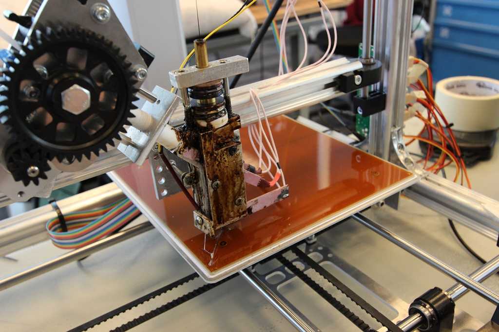
And there are problems with metal inks: Applying too much can cause bleeding and cracking during drying, thus limiting PCB fabrication speeds. Solderability is a particular blind spot – silver can wilt under standard pastes like SAC305, suffering from tin ‘scavenging’ silver during reflow. In addition, inkjet polymers melt at temperatures that standard PCBs easily manage. Fortunately, industry-accepted low-temperature tin-bismuth and indium-based solder pastes are compatible with inkjet-printed PCBs.
Today there are two PCB printers that use ink jetting – the BotFactory SV2 and the Nano Dimension DragonFly. Each printer uses the same process to create multilayer circuitry, although the BotFactory SV2 utilizes inexpensive thermal inkjet heads instead of the piezo heads found in the DragonFly. Nano Dimension has focused on printing for production, whereas BotFactory has emphasized integration of pasting and PCB assembly into a small unit, working on projects with the USAF to automate the entire process. In this regard, BotFactory is unique in the electronics industry and is the only commercial product below $20,000.
Single nozzle jetting
Inkjetting isn’t the only way that nanoparticles can be deposited to create circuitry. An alternative method extrudes lines onto flat surfaces and uses fused-deposition modeling to provide a polymer structure for the traces to inhabit. Pastes are notoriously difficult to control when creating fine traces and spaces, requiring precise control and extremely close contact with the substrate surface.
Here the target surface must be covered twice – first for mapping, then for pasting. The two-step procedure handicaps the scalability of the process for production. Pastes must be devoid of air pockets lest each bubble act as a kind of ‘spring’ and impede the extrusion process. The flip side of using viscous pastes is that metal-loading is higher and it’s possible to deposit metal in thicker layers, boosting conductivity and solderability right off the bat.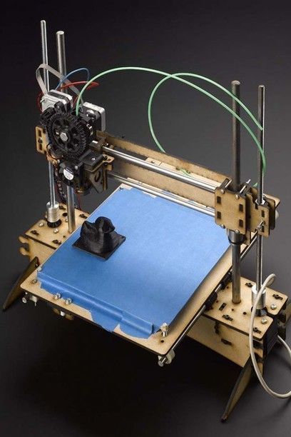 However, at this time, silver is the overwhelming favorite material and thus suffers from the same constraints as inkjet-printed PCBs in regards to silver scavenging.
The first example of 3D printed electronics was demonstrated by Voxel8 in 2015. The printer used FDM and paste extrusion to create basic circuit traces. After delivering early beta systems, Voxel8 switched to industrial-scale fabrication with a broader focus on multi-material printing rather than just electronics. nScrypt has taken a similar tack, creating a more general tool that includes pasting as well as polymer extrusion to create three-dimensional objects with traces within the object.
Example of an nScrypt system extruding conductive traces on an FDM-printed substrate.AM + electroless plating (also abbreviated as AMEP, or 3D-Print-and-Plate) is a completely new category of AM that combines existing additive manufacturing processes and well-understood electroless plating techniques. An object is printed via stereolithography (SLA) or fused-deposition modeling (FDM) using a distinct metal-loaded material that can be electroless-plated afterward.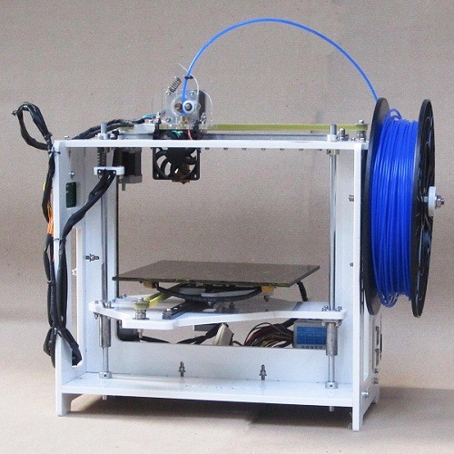 AMEP continues to be a topic of academic research. Last year, researchers at UCLA published results on using SLA to create multi-material prints that could be selectively plated. Using two vats of pure and metal-loaded polymers, the process enhances the existing premise of AM with no extra constraint on fabrication speed.
Palladium, a metal that is traditionally extremely expensive, normally serves as a seed material in this process. But on the other side of the world, UK researchers devised a way of printing less expensive metal on a new polyimide material. Polyimide (also known as Kapton) is highly prized by electrical engineers in flexible and printed electronics for its low thermal expansion and dielectric constant. UK researchers found UV energy can be used to chemically bond silver particles and the polymer chains, providing seeds for plating afterward.
The technology described above has not been commercialized, but the overall concept has been utilized for creating unique antennae at firms like Swissto12. There a high-resolution SLA print is made, coated, and then electro-plated (not electroless plated). Electroplating requires a current to initiate and control the plating process, whereas a PCB often has unconnected traces and vias that require plating.
Overall, the greatest challenge to AMEP is that it cannot create conductors within an object unless there are exposed holes or the PCB undergoes multiple dips into the plating baths. As it stands, the technology has the ability to meet all the technical requirements for high-performance PCBs, including ease-of-solderability and high-thermal tolerances.
What it’s not
There is some confusion about what is and isn’t ‘AM electronics,’ and certain lines have been drawn. In the AM industry overall, any process that uses subtractive processes is not additive manufacturing. So it is fair to argue that any process that builds circuitry on pre-existing substrates or augments AM with subtractive processes is not 3D-printed electronics.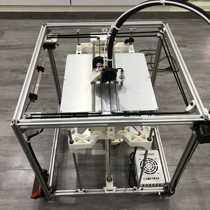 Consider the traditional PCB: UV-curable polymers mask copper foils, utilizing a process and materials seen in AM technologies like inkjet printing and stereolithography. By conveniently ignoring the drilling process for vias and shaping, one could argue that PCBs are made with AM when they clearly are not.
When an entire model is fabricated using AM, it typically has characteristics and form factors that go beyond what would be possible if subtractive fabrication is included. In other words, use of subtractive processes detracts from the entire point of adopting AM.
An example of a semi-additive process that is commonly cited as 3D-printed electronics is Laser Directed Structuring, a technique developed by LPKF. Essentially, an object consists of an injection-molded plastic that has been filled or coated by an organometallic compound. When a laser applies a circuit pattern to the surface, metallic seeds form and create an electroless nickel or copper plating. The technology is limited by the reach of the laser, inhibiting the possibility of allowing conductors to pass thru the object.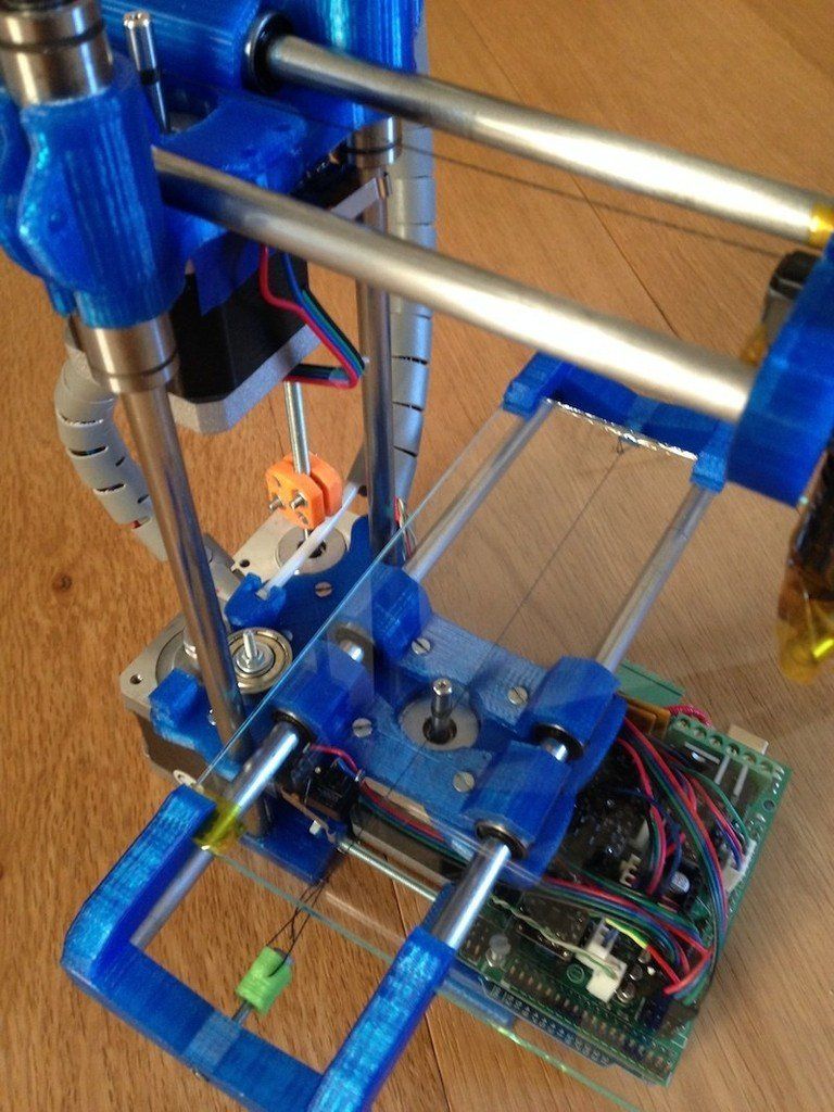 Thus LDS parts are not true 3D PCBs by any means.
The same limitation also applies to aerosol jetting, a concept commercialized by Optomec. Here a carrier gas (nitrogen typically) jets out of a fine nozzle at high speed and carries a fine suspension of materials such as nanoparticle metal inks. The wide variety of viscosity, metal-loading and material choice makes aerosol jetting a candidate for creating sensors on objects, overcoming the limited choice of materials for LDS. As both processes utilize non-AM elements, they arguably do not create 3D-printed electronic devices.
Credible advances in materials, metals and polymers have made it possible to 3D-print PCBs that are useful in many applications today. However, the 3D-printed circuit board made in a few hours which is a perfect replica of a traditional PCB is the Mount Everest of AM. The most mature technique is inkjet printing; it comes closest to reaching the necessary geometric and electric properties, with materials advancing quickly to meet the thermal and mechanical needs. Extrusion is well-understood but hard to scale, and its fundamental capabilities are uneven. AM-EP is the dark horse in the race, combining old and new techniques to provide another path to the 3D PCB.
Ultimately, all technologies can be viable paths to reducing PCB size and shortening traces, yielding lighter devices in forms that would have been unthinkable just ten years ago.
BotFactory Inc.
www.botfactory.co/
What's Possible Now and in the Future?
Ziv Cohen
Application Manager, Nano Dimension
The semiconductor industry gets a lot of attention—and for good reason. Integrated circuits make technology possible, and these devices are built on the back of semiconductors.
Semiconductor manufacturing processes have come a long way since Robert Noyce invented the integrated circuit in 1959. With the rise of Industry 4.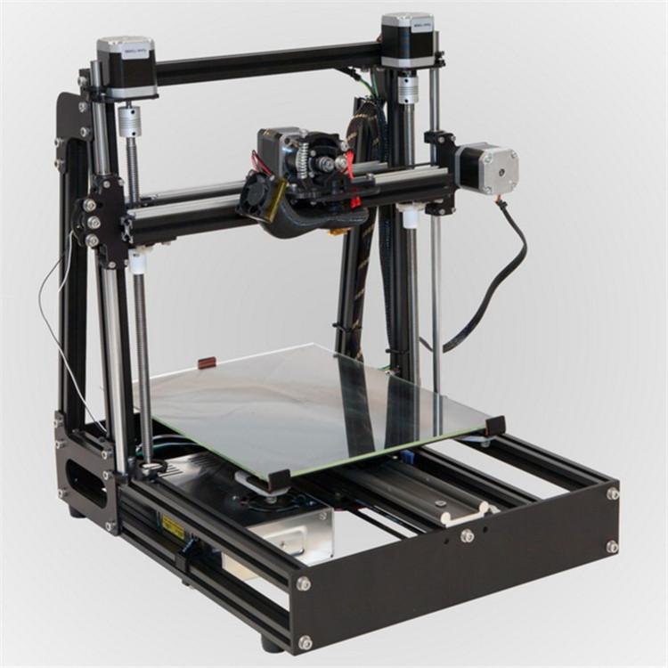 0 and the wide array of additive manufacturing processes, one naturally wonders whether the electronics industry will advance to 3D printing integrated circuits at full scale.
In this discussion, the question naturally arises: Why use additive manufacturing processes to produce integrated circuits? 3D printing is already being used to produce fully-functional PCBs with unique geometry, interconnect architecture, and various levels of component embedding. The ability to 3D print integrated circuits and other semiconductor devices directly into a PCB allows low-volume fabrication of highly specialized devices with unique form factor and capabilities.
IC dies on a silicon wafer
The Current State of 3D Printing Integrated Circuits
Silicon, III-V, and II-VI semiconductor manufacturing processes are highly advanced and are used to produce integrated circuits with less than 10 nm gate sizes. Currently, the most advanced 3D printing processes provide near micron-level resolution and co-deposition of multiple materials.
Co-deposition is critical for 3D printing integrated circuits because conductors and semiconducting materials must be printed simultaneously. The resolution of the most advanced 3D printing systems must still improve before VLSI is possible. In addition to improving device performance, miniaturization will provide much lower power consumption for switching logic gates.
As an example of what is currently possible with 3D printing integrated circuits, researchers at the Air Force Research Laboratory and American Semiconductor recently 3D printed microcontroller SoCs from polymers on a flexible silicon substrate. These microcontroller units offer 7000x memory compared to other flexible integrated circuits at the time. Some envisioned applications include environmental or strain sensing, as well as munitions inventory monitoring.
A flexible microcontroller integrated circuit. This circuit was fabricated using polymers on silicon.
Currently, thin-film transistors (TFTs), diodes, LEDs, can be 3D printed from organic polymers with commercially available and experimental systems.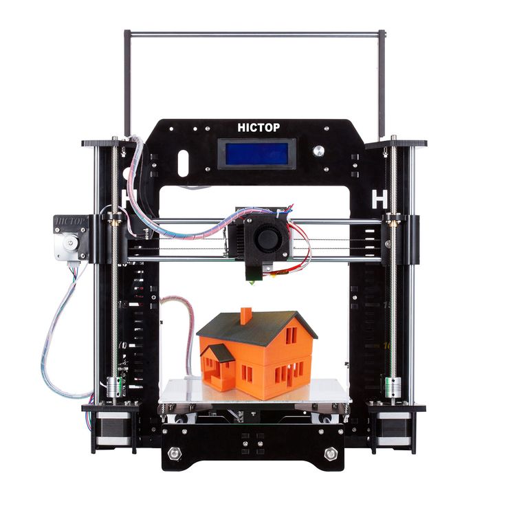 The 3D-printed TFTs can have various contact/gate configurations and can easily be scaled horizontally and vertically. Polymers can be easily doped and functionalized, allowing their electronic and optical properties to be tuned to meet the demands of different devices.
Using polymers on a semiconductor wafer is a natural route to pursue 3D printing integrated circuits. Electrical contacts can already be deposited in an additive manner through a mask (i.e., thermal evaporation, PVD, or CVD), followed by deposition of semiconducting polymers and larger conductive tracks with a 3D printer. Their adaptability to low-temperature processes also makes them ideal for 3D printing integrated circuits directly on standard semiconductor wafers.
Other researchers are working on advancing additive manufacturing processes and materials to enable 3D printing integrated circuits. As an example, the University of Hamburg and Deutsches Elektronen-Synchrotron developed a 3D printing process that can enable the fabrication of integrated circuits.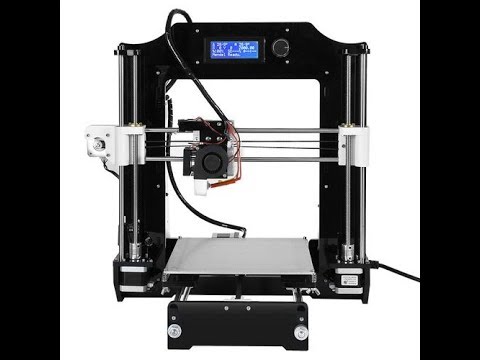 This process uses a mesh of ~20 nm silver nanowires as conductive elements and a thin film of polymer as an insulator or semiconducting material. This process is still in the research phase, but it illustrates how unique nanostructures can be used to fabricate semiconductor devices that rival silicon integrated circuits.
The Economics of 3D Printing Integrated Circuits
In any manufacturing process, the cost structure involved in manufacturing is an important driver of the price of a finished device. Integrated circuits succeed or fail based on the cost of the die on the wafer—when more dies can be placed on a single wafer, the costs per device decreases. The cost structure of integrated circuit manufacturing is responsible for the high costs of highly specialized, low-volume integrated circuits. An excellent example can be found in the defense industry, where the cost of a single FPGA for a complex system can reach tens of thousands of dollars.
The unique cost structure of 3D printed devices changes this economic dynamic. 3D printed integrated circuits do not need to be produced on a wafer and can even be manufactured individually. Because 3D printed devices can be produced with predictable fabrication time, and the cost structure is complexity agnostic, the costs involved in 3D printing electronics depends on the weight of the materials used. This makes 3D-printed integrated circuits highly cost competitive for low-volume production compared to devices produced on semiconductor wafers with standard processes.
Challenges in 3D Printing Integrated Circuits
Commercially available printers are becoming more advanced, and the range of materials useful with these systems is expanding. That being said, there are still some challenges in 3D printing integrated circuits with the same level of performance as integrated circuits on monolithic circuits. These challenges involve finding rigid semiconducting materials that can be adapted to a standard 3D printing process, optimizing these materials for different frequency bands, and bringing printing resolution closer to the nanometer level.
A lithographic process may aid in 3D printing integrated circuits with less than one-micron resolution.
The fact losses and parasitics can be optimized in a variety of polymers for specific frequency bands allows these materials to compete with GaN, which is currently the best option for fabricating RF integrated circuits and SoCs. GaN is currently used in the best SoCs for high-frequency radar modules, as well as in power amplifiers for microwave and mmWave signal chains. Polymers are already used to 3D print substrates for building flexible and nonplanar PCBs, so it is natural to extend these materials to integrated circuits and other semiconductor devices.
To increase the printing resolution, the additive manufacturing industry may need to devise a completely new printing process. Currently, inkjet 3D printing provides among the highest resolution features for 3D printing PCBs, but it remains to be seen if this process can be improved to provide resolution less than 1 micron.![]() The future of 3D printing integrated circuits will likely adapt a photolithography process or functional self-assembly process to produce integrated circuits with competitive resolution.
The future of 3D printing integrated circuits will likely adapt a photolithography process or functional self-assembly process to produce integrated circuits with competitive resolution.
Innovative companies that are interested in 3D printing integrated circuits and fully-functional PCBs need an additive manufacturing system designed for full-scale production of complex electronics. The DragonFly LDM system from Nano Dimension is ideal for in-house full-scale PCB fabrication of complex electronics with a planar or non-planar architecture. Designers can embed standard components and can experiment with 3D-printed integrated circuits. Read a case study or contact us today to learn more about the DragonFly LDM system.
3d printing | 3D printing applications
Ziv Cohen
Application Manager, Nano Dimension
Ziv Cohen has both an MBA and a bachelor’s degree in physics and engineering from Ben Gurion University, as well as more than 20 years of experience in increasingly responsible roles within R&D. In his latest position, he was part of Mantis Vision team—offering advanced 3D Content Capture and Sharing technologies for 3D platforms. The experience that he brings with him is extensive and varied in fields such as satellites, 3D, electronic engineering, and cellular communications. As our Application Manager, he’ll be ensuring the objectives of our customers and creating new technology to prototype and manufacture your PCBs.
3D printing for the newest ones. From A to Z. Kinematics.
In this article, we will understand what 3D printing is and what the kinematics of 3D printers are.
1. 3D printing. What does she taste like?
There are a lot of printing technologies, from FDM (FFF), which is used by more than 90% of printers on this portal, to SLA / DLP / LCD (with photopolymers) and SLS / SLM (powder sintering using powerful lasers)
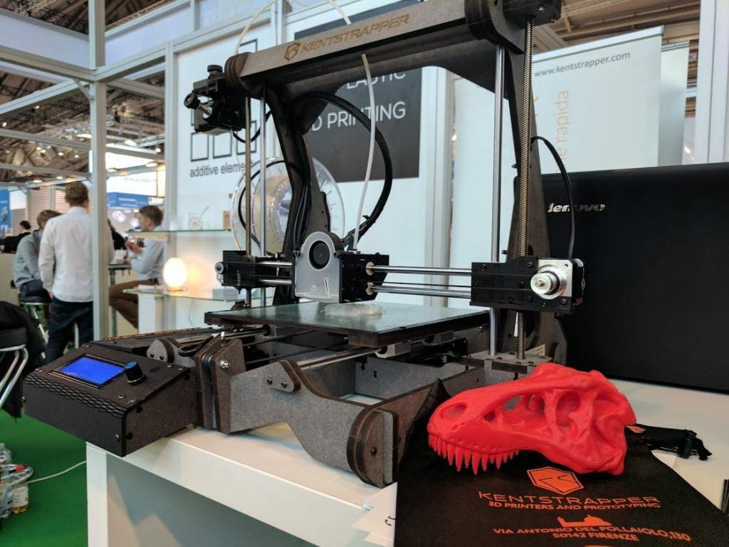
At the initial stage, we are interested in FDM - layer-by-layer deposition of a molten rod.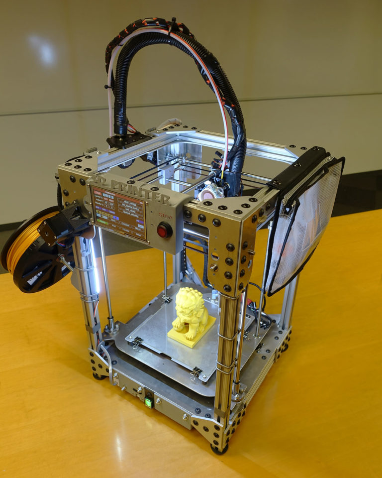 The picture below shows the hot end (Hot end) - that part of the 3D printer extruder where the rod is melted.
The plastic rod is fed through the Teflon tube and radiator into the thermal barrier, and through it into the heating block. It melts there and exits through the nozzle. The nozzle has a certain diameter, which is marked on it.
It is often made of brass, as the material is inexpensive and easy to process. The accuracy of printing depends on the nozzle. The smaller the nozzle, the more threads fit into one mm.
Heater and thermistor provide feedback for temperature control and regulation. That is, the voltage supply to the heater depends on what temperature the thermistor shows, and the processor compares it with the set one.
Next we see the heating block. A nozzle is screwed into it on one side, and a thermal barrier on the other.
The thermal barrier is used to minimize the heating of the plastic above the thermoblock.
[IMG]http://3d-makers.nethouse.ru/static/img/0000/0002/6151/26151635.2ofdbr37y8.W665.jpg[/IMG]
Most often made of stainless steel. It has a lower thermal conductivity than conventional, unalloyed steel. To prevent the rod from melting above the thermal block, a radiator is screwed on top of the thermal barrier and blown by a cooler. Everything is quite simple.
It is very common for melted plastic to leak through threads.
This means that the nozzle has not pressed the thermal barrier in the heater block. Therefore, when disassembling and assembling the hot end, we first screw the thermal barrier into the heating block, and then press it with a nozzle. If, when you twist the nozzle, there is a gap between the end of the nozzle and the heating block, then this is normal, the gap in order to press the thermal barrier with the nozzle.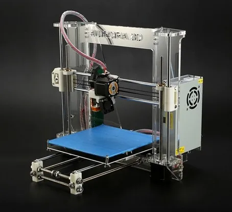
In order to feed the bar at the right time and in the right place, a feeder is needed, that is, a bar feeder.
Sometimes it is performed combined with a hot end, and then this type of extruder (this is all together a hot end + feeder) is called a direct (direct), that is, a direct feed, without tubes.
The same feeder is made separately, and the bar is fed through a fluoroplastic tube. Such a system is called bowden.
This is to lighten the moving part. As for the positive aspects and disadvantages - each design undoubtedly has them.
Direct extruder:
1. Advantages:
a) More reliable due to fewer plastic feed connections;
b) Less picky about the materials it prints on, in particular rubber-based rubber is problematic to print on bowden extruders;
2. Disadvantages:
a) Large weight, due to this, during acceleration / deceleration, small ripples can be observed on the surface of the part;
b) Dimensions. They greatly affect the plot area. Let's say, like in the picture above, a direct with 4 colors would be very huge. And for Bowden, this is just right.
Bowden extruder:
1. Advantages:
b) The coil does not twitch after the model, otherwise, when the coil turns with the direct are entangled, we will get a skip of steps, since the carriage will pull the coil along with it.
2. Disadvantages:
a) Retract settings (pulling the rod back during idle movements so that the molten plastic does not ooze out of the nozzle while expanding) is more difficult, since the rod is smaller than the inner diameter of the tube, it tends to stretch;
b) It is more difficult than on direct to select all gaps in order to print with various flexible plastics. Everyone who says that printing on Bowden is impossible with flexible plastics is blatantly lying. I am typing. And quite successfully.
Now we go directly to the mechanics and its calibration.
Part 2. Mechanics. What, how and what pulls?
There is a very limited number of kinematic schemes for which the firmware is written, and which work out movements quite tolerably.
Consider everything, from the most common:
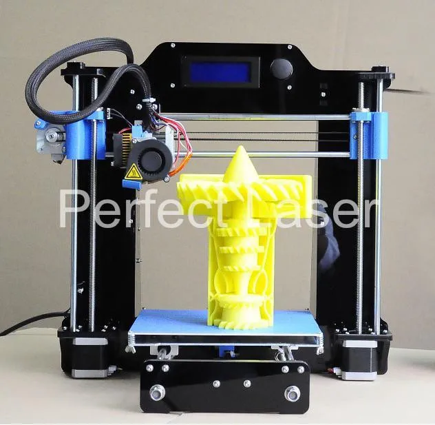
1. Design and kinematics from Joseph Pryusha (no need to read Prus, Prasha and so on, this is the name of a person, after all).
Movement along each of the axes is provided by its own independent motor. Movement along the Z axis (up and down) is provided with the help of 2 motors and with the help of a kinematic screw-nut pair. M5 studs are often used; recently, screws with trapezoidal threads have been increasingly installed.
Here is a trapezoidal screw. How studs with metric threads look I will not apply.
The only thing I will explain about moving along the studs and trapeziums is that for the production of trapeziums they take a calibrated rod and roll it between rollers at an angle. Get helical grooves. This method, a priori, gives better quality and step accuracy than building studs of far from the highest quality.
To connect 2 motors to one axle (and 1 connector) at the same time, the following scheme is used.
Connection in series, 2 wires soldered and the rest crimped. You can ignore the colors, the main thing is that the windings ring. A and B are windings, and 1 and 2 are terminals.
Advantages of this kinematics:
1) Independent movement of each axis. It is easy to catch to understand which axis skips steps. Kinematics migrated to printers from CNC milling, so many manufacturers make desktop milling machines on it, instead of an extruder they offer to install a laser for engraving or cutting, a spindle for milling boards, an extruder for chocolate or even dough to bake pancakes.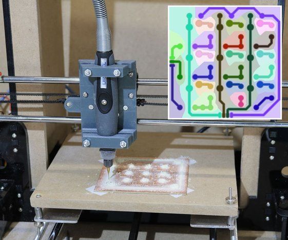
Pictured above is a ZMorph printer. It can be used as a printer (with one or two extruders), as an engraver (Dremel machine), as an engraving laser, and so on. A small presentation video.
Milling machine with this kinematics. I note that for milling it is necessary to use a screw-nut pair to move, and not belts, they are not designed for such loads.
Chocolate and pancake printers according to your design. It is worth noting that it is not recommended to use chocolates like Alenka or Babaevsky, since they already contain cocoa butter and during processing (melting and hardening) the result is unpredictable. It is necessary to use chocolate in galettes, such as the Belgian Callebaut, as it does not contain cocoa butter, and must be added for the final filling.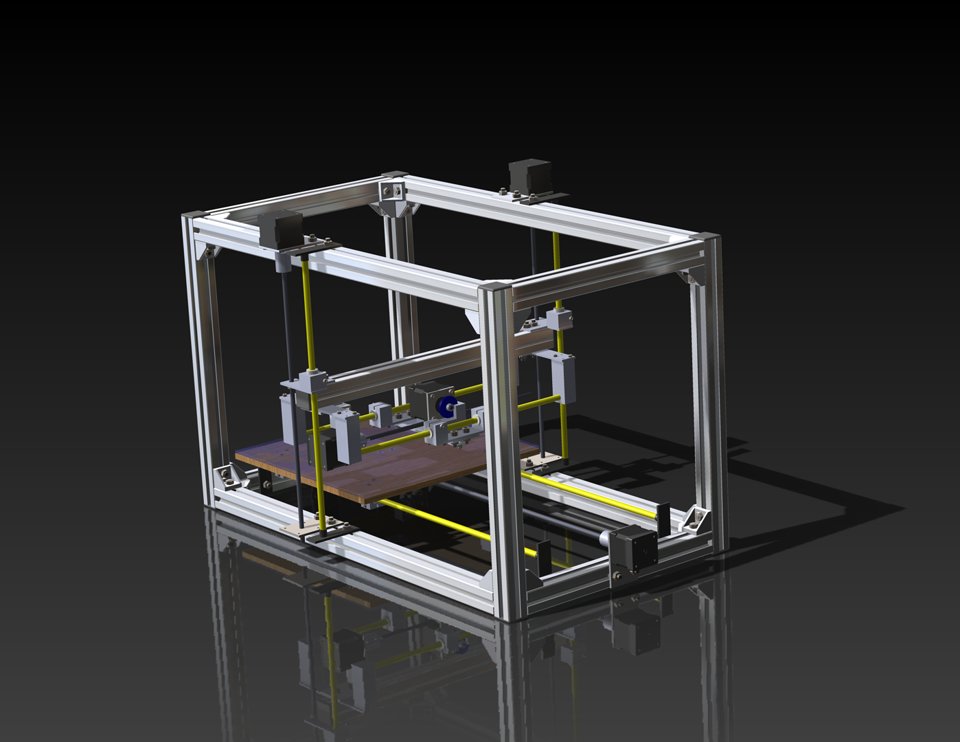 For this type of chocolate, each pack has a graph of its crystallization. It is desirable to take the oil in powder form. For more information, I recommend Google about tempering chocolate.
2) The kinematics are as easy as two fingers. Its very easy to assemble. Many even collect on old DVD drives.
3) Easily changed to suit your needs, the size of the extruder is also of little importance, as it protrudes forward and does not interfere with the movement of other parts. Many people put a second extruder, or make the nozzles swing so that the nozzles of one extruder do not remain on the part when printing with the second nozzle.
Therefore, for this kinematics, there are a huge number of extruder variations, for every taste, on a very famous site.
Disadvantages of this kinematics:
1) Complicated calibration. Yes, since the table 'jumps', it is difficult to print with high quality, because the part + table, with a sharp change in the direction of movement by inertia, tend to go further.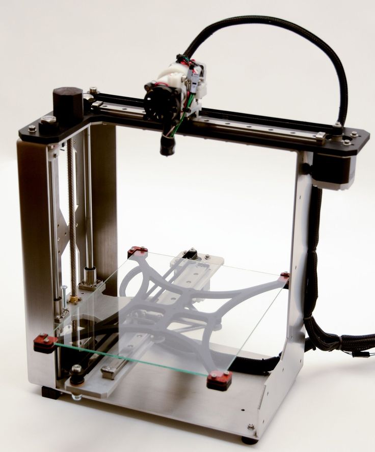 Ugly print artifacts are obtained. And for high-quality printing, you need a small speed. In general, it all depends on the frame. My first printer was a Chinese pryusha. With acrylic frame.
Acrylic is not very hard. And as you know, the rigidity of the printer, like the CNC, is the most important thing. And it was possible to print more or less qualitatively at speeds of 40-50 mm / s. Then I transplanted it to a steel frame from MZTO.
And after that, without loss of print quality, I was able to print at speeds up to 100 mm / s.
2) Delamination. Due to the open case and the constantly moving platform, hot air, one might say, is constantly blown away, and by cooling the part excessively with drafts, we increase the already large shrinkage of nylons, abs and other capricious plastics. Someone sews a fur coat for a fabric printer, and someone is content with boxes.
But the goal, as always, is the same - to reduce the effect of drafts on the shrinkage of the part.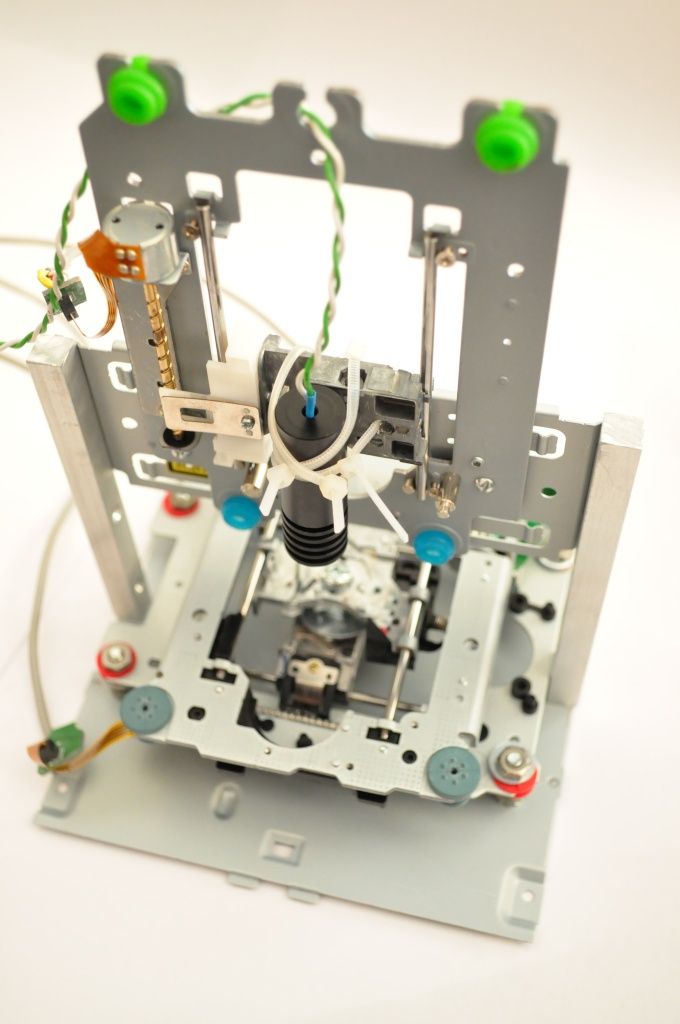
Key points for correct calibration of printers with this kinematics:
1) Place the printer on a level surface. Preferably horizontal. This requires a bubble level. Next, set the level of the position of the X axis.
2) Transfer to the home position. It is done either in the printer menu with the Home / Home command, if you are printing from a computer, then either with the G28 command in the command line, or with special buttons with the house icon.
Next, tighten the table screw so that the nozzle touches the glass. It did not press on the glass, but touched. We look at the light and twist. After that, move the extruder to another corner with the arrows in + X, + Y from the PC, or through menu
Turn the screw in the same way until it touches the nozzle. And repeat the operation for the remaining points.
I will try to save you from mistakes.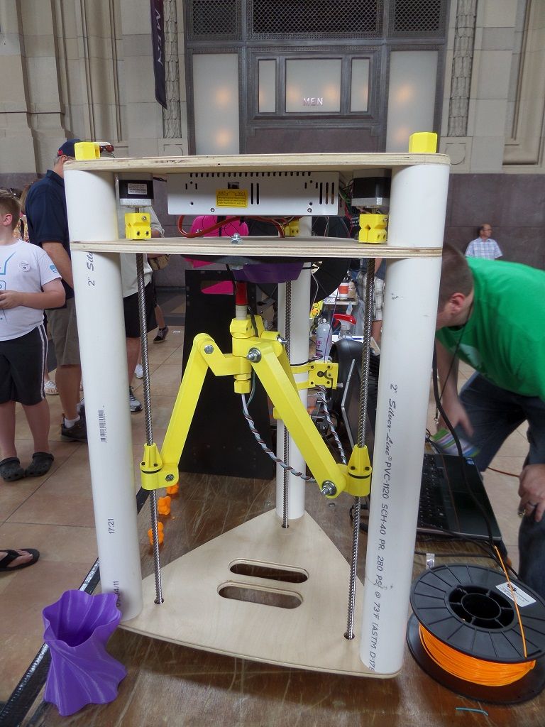 In the photo of the printer above, the glass on the table is fastened with as many as 8 clamps. And it is quite possible that there will be a hump in the center. To avoid such problems, the glass should be fixed with 3 clamps. The plane is built, as is known from descriptive geometry, by 3 points. And calibration will be easier in this case. Just tighten the screw over the limit switch in Z.
For the nozzle to touch the glass in the middle of the side with 1 clip. Then we distill the hot end into the corner where there is another clamp, tighten the table screw, and repeat the operation with another angle.
Regarding wobble.
All sorts of anti-wobble systems such as installing a bearing in the upper support do not work.
Just because putting 4 far from perfectly even cylinders in perfect parallel and in the same plane is an unrealistic task. Especially on a flimsy acrylic frame with printed details.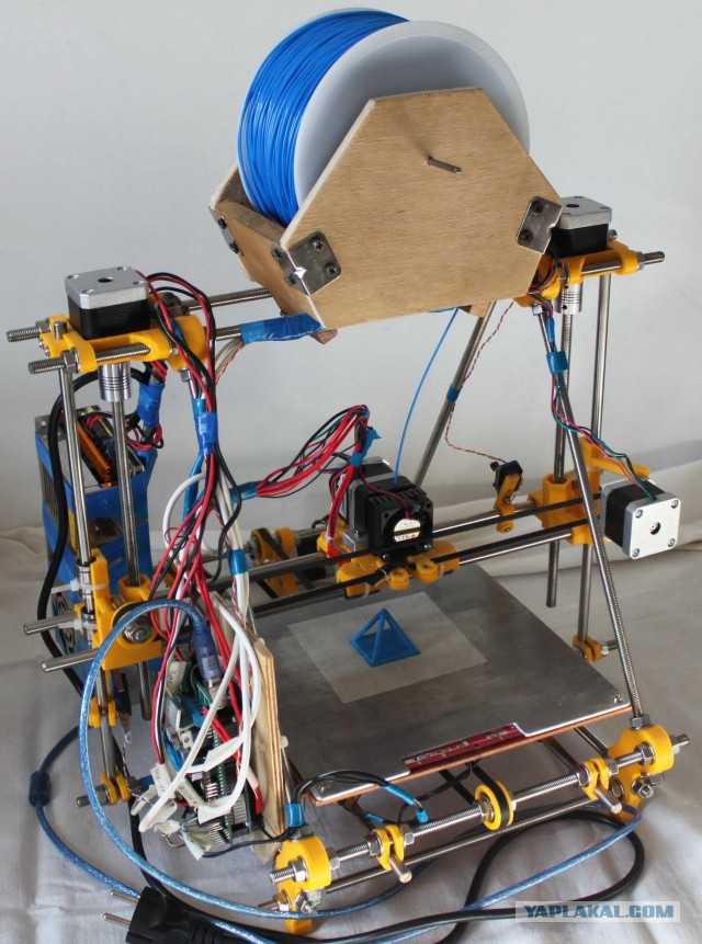 Therefore, if we take the straightness of the shafts as a constant, and set them parallel on the frame (purely hypothetically), and release the screws (from below the coupling for attaching to the motor) and nuts for attaching the X axis. Due to their curvature, the screws will spin like a mixer, but on printing will not be affected.
Otherwise, the design will work on who will be stronger in terms of bending resistance. And it will turn out far from a flat wall. Do you need it?
2. Kinematic design of Felix printers.
There are many such printers, such ones are made by MZTO (mz3d.ru), already mentioned by Felix. In fact, the kinematics are the same as those of the Prusa. axes independent of each other. Only now the table does not travel along one axis, but along two at once. Along the Z axis, and along the Y axis.
The design of the table is something like this.
A platform rides on the Z shafts. The engine hangs at the back. The table moves along the rails with the help of a belt. The hotend moves only along one axis. The design is very funny, since the table weighs much more than the hotend, and they try to move it along 2 axes at once.
Advantages of this kinematics:
1) There is no second motor along the Z axis. There is no notorious wobble simply because there are 2 shafts and 1 propeller. The screw should also not be fixed from above. If it's not a ball screw.
Ball screw is a separate issue. If we take a high-quality ball screw, say, from the same Hiwin, then it is manufactured according to at least the 7th accuracy class (if rolled, and if polished, then the class is even higher) and must be installed in bearing supports. On the drive side there are 2 back-to-back angular contact bearings, and on the other end a radial bearing with a loose fit to compensate for thermal expansion.
The purpose of mounting a ball screw is to ensure movement accuracy.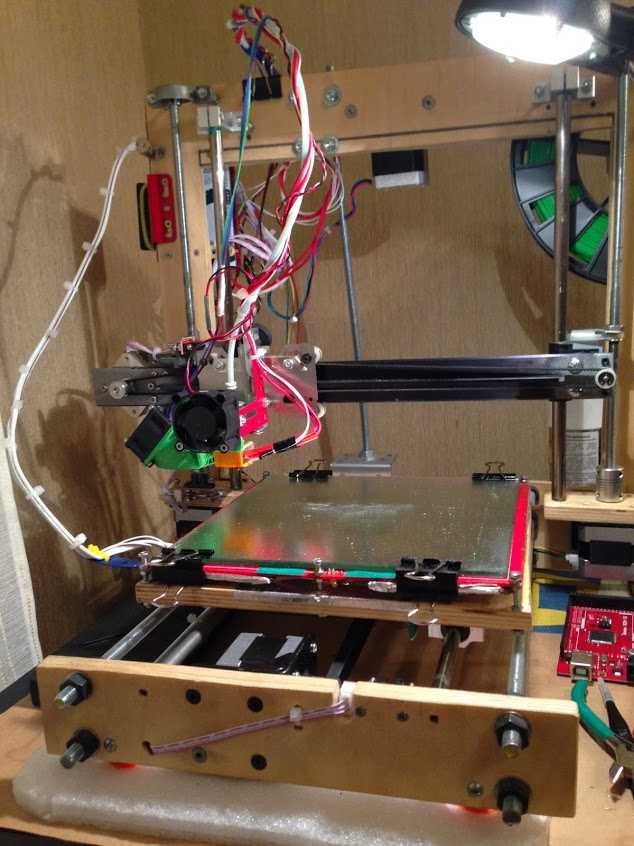 If it is installed incorrectly, money is wasted, and the accuracy will not be higher than a screw-nut pair with a trapezoidal thread. For FDM, trapezoidal accuracy is more than enough.
2) Plenty of space for a direct extruder. As in the previous kinematics, there is room for creativity, to select the one and only extruder that you like.
3) Rigid frame. It is possible to make a normal frame. Rigid, durable. Yes, even cast iron. The guys from Felix decided not to bother their heads and sculpt from an aluminum profile. MZTO went further, bent the steel sheet. And the shelf for the installation of the table was milled from a sheet of aluminum.
4) If we take the design of Felix on the profile, then by replacing a pair of pieces of the profile and the Z screw, you can increase the print area.
Just be sure to add stiffness. And it will turn out like a miracle of design thought. Big, meaningless and merciless.
Kinematic disadvantages:
1) Undoubtedly large twitching masses. The table back and forth, and if you turn on the movement along Z during idle movements (Z-hope), then there will be a disco.
2) There is no way to make him a normal heat chamber. The table moves back and forth and the temperature gradient simply blows away. Hence the problems when printing with nylons or ABS. Small drafts in the room will easily show you where the crayfish hibernate, how the material shrinks.
The calibration of the table of this printer is similar to the calibration of the Prusa table, only slightly simpler. It is easier due to the fact that you do not need to level the X-axis, it is automatically set when assembling the frame. We bring the nozzle to the table and twist the lambs.
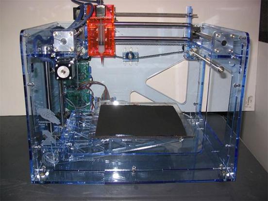
3. Ultimaker kinematics.
One of the most common variations of Cartesian kinematics.
There are not very many such printers, but they do exist. Variation from Zortrax deserves attention. A variant of the same Raise is closer to the classics.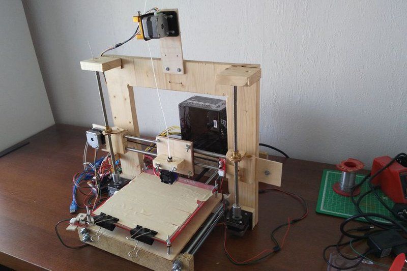
Zortrax has twin shafts, the reason is simple - they have a direct extruder with a full size Nema 17 motor. Raise Dual has a double direct extruder, so the classic 6 mm shafts are replaced by 8 mm. And the total weight of the 'head' is almost 900 grams.
Kinematics built entirely on shafts. They act both as guides and as pulleys. Kinematics also refers to Cartesian kinematics with independent movement along each axis by its own motor. Very picky about the straightness of the shafts. If you use curved shafts, you can get very funny artifacts on the walls of models. And they will be on all 3 coordinates. Most often it looks like a different thickness of the first layer and small waves along the walls. Therefore, all the salt and the high price of the original Ultimaker is only in high-quality components. Namely, in straight shafts. The belts are often used as ring belts, which simplifies their tensioning system, since it is important that all 4 belts are equally tensioned.
Advantages of this kinematics:
1) The table only moves along one axis. vertical. And the temperature gradient in no way suffers from this. The table is cantilever, so it is desirable to provide stiffeners or take this into account with the thickness of the table.
The metal fold on the table acts as a stiffener.
Many Chinese clones are equipped with such stiffening ribs for the table.
2) Despite the seeming complexity of the kinematic scheme, it is simple and each axis moves with its own motor.
3) The body is closed, which protects against drafts, and therefore delamination. Some put an acrylic door to heighten the effect.
Disadvantages of kinematics:
1) For good printing, it is not enough to buy a pack of even rollers. Collecting all these shafts correctly together is another task. At the same time and buy good bearings. Not that, Chinese junk, which is often sold on Ali, but normal bearings. If the bearings that are placed in the housing rotate poorly, the print will be jerky and with a shift in the layers. The consequences can be asked from Vanya (Plastmaska). Also, when buying leopard bushings, brass bearings with graphite inserts, be prepared for the fact that they will play. And if there is a backlash, the whole structure will knock.
And also, the Chinese like to push brass instead of bronze. And with even wear of brass and graphite, there will be an oily sticky black film on the shafts, which will make the movements harder. Ilya (tiger) offers good bushings. He also wrote about these difficulties.
2) All shaft parallels must be set correctly. I suggest using this device.
4 shafts that go along the walls of the body automatically stand up correctly, but it is important to set the crosspiece correctly in order to get angles 90 degrees in the XY plane.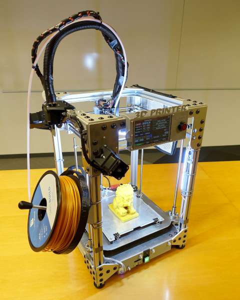
3) The design does not provide for an increase in the printable area with a couple of profile pieces, so the size of the hotend matters. Direct is difficult to put, but you can if you want.
Calibrating the table couldn't be easier. The table is often on 3 attachment points. Move the hot end by 3 points and turn the thumbs.
4. Kinematics used by Makerbot.
Also very widespread. In particular, printers from Makerbot, BQ, BCN3D, Magnum, magnum clone Zenit and quite tolerable makerbot replicas Flashforge and Hori work on this kinematic scheme.
In this case we have independent movement of each of the axes, with a Z table and all the resulting sides.
The main drawback is that the engine hangs on one side of the rolling beam, creating a kind of imbalance. This shortcoming was compensated in a two-extruder version - BCN3D Sigma. There, each bowden head has its own engine to move along the beam. And they are installed at the edges of the beam and balance each other. For uniform movement of each of the edges of the beam, 2 shafts, pulleys and belts are used. Belts must be tensioned equally.
Advantages of kinematics:
1) Independent movement of each axis.
2) Z-moving table. The temperature gradient does not suffer from 'blowing'.
3) Enclosed body. If not closed, then there is a quite normal chance from the point of view of aesthetics to close it.
4) Scalable kinematics possible. Various BigREPs and others with 1m print areas use exactly this kinematics, as various H-bot/CoreXYs will ring like hell due to the presence of 4-5m belts and their stretching during accelerations.
Disadvantages of kinematics:
1) Unbalanced masses on the moving beam, hence the maximum print speed, with acceptable quality no more than 60-80 mm/s. Some manage to balance them and it is not so noticeable.
2) Bulky structures on the shafts to avoid unbalance during movements.
3) Make sure that the belt tensions on the right and left are the same.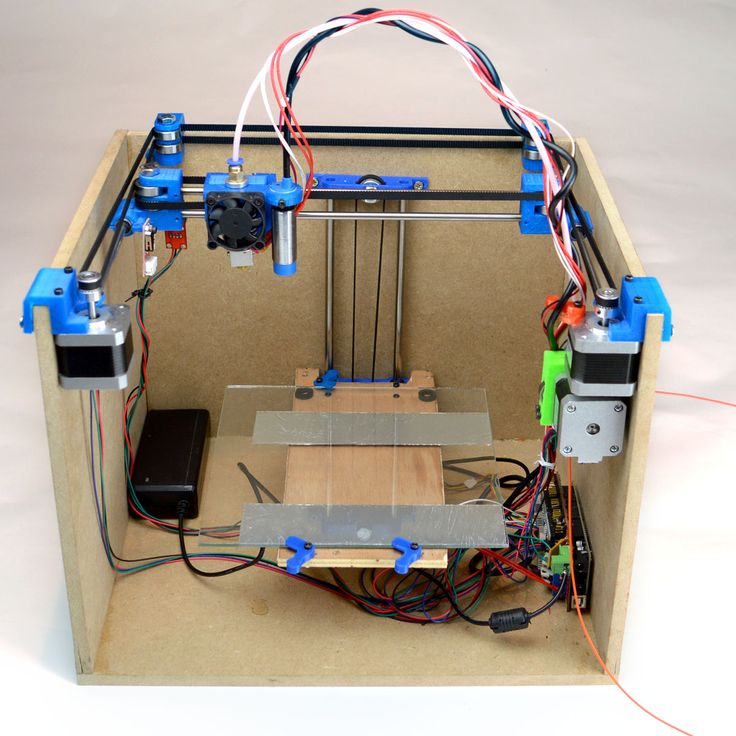
4. H-bot/CoreXY kinematics.
Next in distribution. Also Cartesian. Two motors are stationary, but move the carriage along the rails with one long piece of belt, or with two, but shorter. The math is more complicated than the previous ones, as it is necessary to synchronize the rotation of both motor rotors. That is, to move along each axis, you need to rotate both motors, and to move diagonally, only 1.
[IMG]http://www.doublejumpelectric.com/projects/core_xy/pics/hbot.svg[/IMG]
In fact, the mathematics for rotating motors is the same, but the implementation in mechanics is different. One of the biggest disadvantages of the H-bot over the CoreXY is that the belt tends to rotate the beam as it moves.
In the picture on the left, this is noticeable, the forces on the right and the forces on the left create a torque. Therefore, to implement this kinematics, the rigidity of the kinematic scheme is necessary. Most often it is implemented in rails.
With rigid beam. Some do, of course, on the shafts, but in the end - this is not a fountain.
And then they realize this and move to the rails.
For they are both easier to assemble and set up, and it is not necessary to invent carriages so that the shafts do not need to be fixed well.
CoreXY, unlike the H-bot, is driven by two belts.
And so, for ease of understanding, I will describe the positive and negative aspects of each variation of this kinematics.
H-bot.
Advantages:
1) Only one belt is needed, and the scheme provides for its operation without twisting.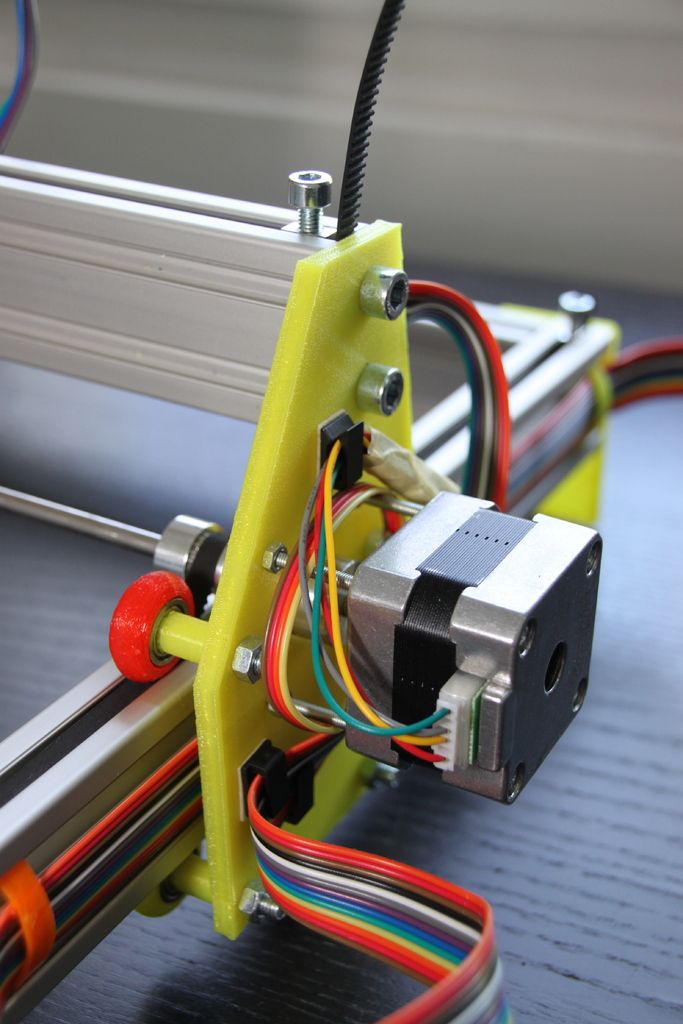
2) It is more convenient to tension one belt than 2, so only one normal tensioner is needed in this scheme.
Even so.
Disadvantages:
1) The belt tends to stretch over time, and since the amount of stretching directly depends on the length, it is necessary to monitor its tension. Otherwise, you will get ugly waves on the surface before the stops.
With a loose belt tension, the carriage will have this play.
2) It is necessary to set the rollers strictly perpendicular to the XY plane, since if the roller is slightly skewed, the belt will be eaten against the roller shoulders. And we will get such a bullshit.
Tested in the skin and ZAV printer. Therefore, I always recommend that the rollers be fixed normally, and not cantilevered, in order to avoid bending the roller axis from belt tension.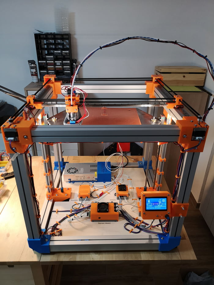
3) Complicated mathematics, due to which at speeds above 100 mm/s there may be problems with the lack of resources of 8 bit boards.
CoreXY.
Advantages:
1) Two short pieces of belt. They are easier to find than one long one.
2) The forces balance the beam, but do not tend to turn it, so these kinematics can also be assembled on shafts.
Disadvantages:
1) There are schemes with belt twisting and belt transition from one level to another - this is not very pleasant for a belt. Especially when one belt rubs against another. This moment is on video.
:{}
2) The difficulty of tightening the belts. They must be tensioned equally, otherwise the tension forces will tend to turn the carriage.
3) Complexity of assembly and development. It is necessary to maintain the verticality of the rollers, relative to the horizontality of the platform for installing motors and rails. A slight misalignment of the rollers will cause the belt to tend to slide down the roller, and if it rests against the shoulder of the roller, it will creak, if the shoulder is large, and if it is small, it will try to drive into it, as in the photo from the h-bot description .
The general disadvantage of kinematics is poor scalability. That is, it is very problematic to set such a kinematics for a print area larger than 300 * 300 simply because of the elongation of the belt during printing. For small printers with high print speeds - one of the best kinematics.
5. Delta kinematics.
The kinematics are based on the movements of the delta robot.
Only the hot end is installed instead of grippers. It has its own set-up problems, but it can take a very long time to print. It is rare when direct extruders are installed, since the effector (a platform for installing a hot end) is often mounted on magnets and it is necessary to unload it as much as possible. But in order to reduce the length of the tube (more specifically, the effect of the length of the tube on the print quality due to the correct adjustment of the retracts (pulling the plastic rod back to reduce its leakage from the expansion)) on the print quality, the extruder is hung on the same carriages, but on separate hangers.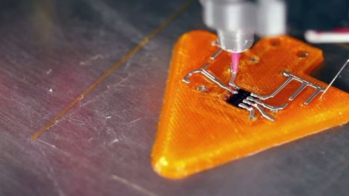 This reduces the length of the bowden tube and increases print quality.
Advantages:
1) Easy to customize. To increase the height, it is enough to buy 3 pieces of a longer profile, and increase the maximum height in the settings.
2) Takes up little space. It is more often high than bulky in length and width, due to this compactness.
3) If you make a light effector (carriage on which the hot end is installed), then you can achieve high speeds without losing print quality.
4) Vertical movement is the same as XY movement. Thus, there is no sticking of linear bearings on the table crossings, as in Cartesian printers, no extra motors rolling on the beam...
5) The absence of protrusions makes it possible to close the housing and stiffen the frame.
6) The aesthetic part - it's more interesting to stick to the work of the delta.
Disadvantages:
1) Difficult mathematics of movements, it is recommended to install 32-bit boards at once.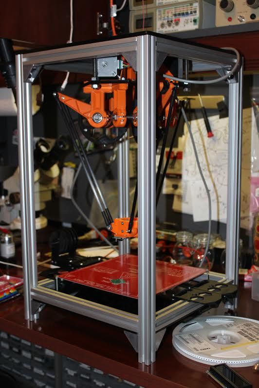
2) Complicated setting. A common problem in tuning is to remove the so-called 'lens', because each rod rotates with a radius, and if the tuning is incorrect, your printed plane will be either a convex or concave lens.
3) It is difficult and expensive to make a rigid frame, so that it would not dangle from the constant jerking of the carriages.
4) Difficulty installing a direct extruder. It turns out to be heavy, and since many deltas are made on magnets, it will not be possible to accelerate. Although, there is one neat and easy solution - installing a ready-made direct extruder with a gearbox. Like E3D Titan Aero or Bondtech BMG.
5) Parts precision problems - any unevenness and misalignment will be visible even if they are on the same axis. And they add up along the axes.
To sum up , do you want a small printer (not larger than 300*300 mm) with nimble kinematics? Then you should go to Ultimaker or H-bot/CoreXY. Need a printer with a large printable area or 2 independent extruders? Then to Makerbot. If you print vases, hookahs and sufficiently high details - delta. For everything else, there is a classic - Prusa. Experiments with double carriages, chocolate, engravings? Yes, anything. And most importantly - cheap.
You can even screw on 4 colors.
Kinematics of 3D printers: what are the best types
Kinematics of 3D printers - which device to choose?
The print quality of a 3D printer and how it works depends on several factors. One of the important indicators is kinematics. This article discusses its main types and their features.
- What is the kinematics of 3D printers?
- Types and types of kinematics
What is the kinematics of 3D printers?
Each 3D printer has its own kinematics.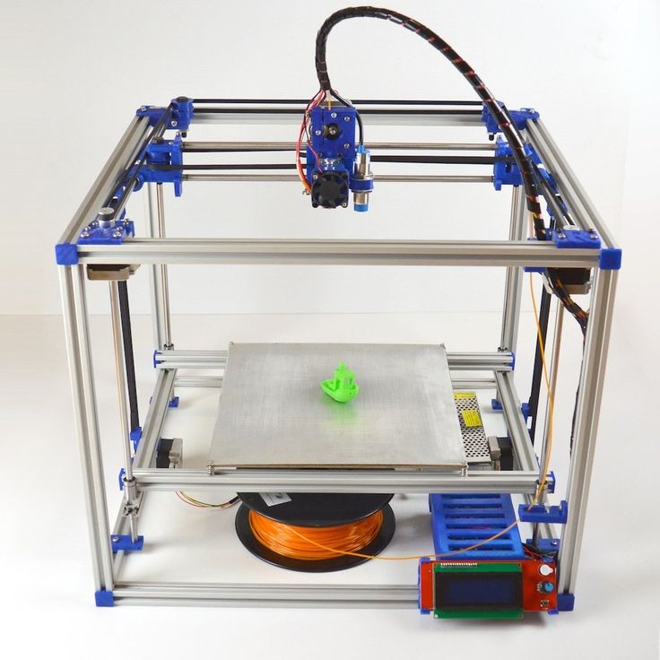 Models are equipped with a platform and an extruder. These parts move in a certain direction relative to each other. Kinematics in such a device means the scheme along which the extruder and platform move.
Types and types
There are five types of 3D printer kinematics. The principle of operation of the device and the method of processing the workpiece depend on their features.
Cartesian 3D printers
The most common are 3D printers with Cartesian kinematics. They are based on the Cartesian coordinate system, they work in the X, Y and Z axes. They set the coordinates by which the print head changes position relative to the platform. The printhead has limitations in terms of movement in three axes.
- The extruder moves up when the platform moves in the horizontal X or Y axis.
- The platform moves up in the Z axis, the extruder can move in the horizontal directions at this moment.
- The platform moves along one of the axes in height, the extruder rises along the other axis.
- The platform is static and does not move, the extruder moves in all three axes.
- The extruder moves along the coordinates in height, and the platform moves along the X and Y axes.
The most common options during operation are the first and second.
Cartesian kinematics has a number of advantages.
- This is a simple motion pattern suitable for hobby printing. Many budget models work on its basis.
- The printer can be produced in any dimensions, if necessary, it is upgraded.
- Consumables are freely available. Users are offered a large number of materials and colors.
- The printers can be shipped unassembled. This feature allows beginners in the world of 3D printing to understand the principle of the mechanism.
- Devices based on the Cartesian system are suitable for mass production of parts. They are designed to create blanks of different sizes.
Among the shortcomings of printers built on the principle of three coordinate systems, two factors stand out:
- models are bulky, after assembly they take up a lot of space on the desktop;
- The print speed is slow.

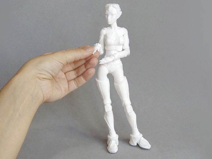
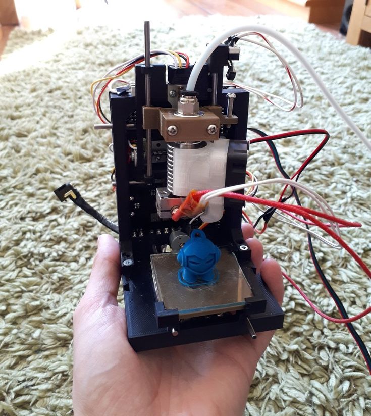
Cartesian kinematic printers suitable for hobby printing. They help beginners understand the process of work and learn how to create models.
Example of printing on a device with Cartesian kinematics.
Varieties of Cartesian kinematics CoreXY and H-Bot
The CoreXY has two feed belts, while the H-Bot has only one, but it is long - this is the main difference between the two varieties. The common feature in these devices based on Cartesian kinematics is that the platform moves only along the Z axis. The horizontal X and Y axes are moved by a pair of motors mounted on the frame.
Two motors are responsible for the movement along the horizontal axes, one motor along the vertical ones. Such kinematics is common not only in amateur printers, but also in professional ones.
CoreXY and H-Bot based 3D printers are more expensive than conventional Cartesian models. For the production of their cases, a metal alloy or composite materials are used.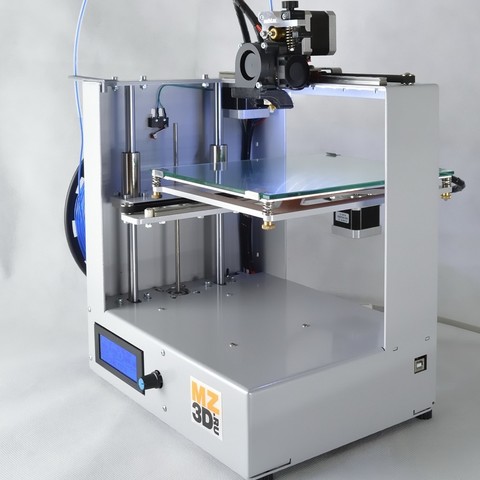 Rail guides unleash the potential of high-quality printing. This kinematics allows you to achieve good detail with fast printing.
The advantages of CoreXY and H-Bot are:
- high print speed;
- quality detailing of models;
- professional grade use.
But not without drawbacks:
- H-Bot is not implemented on steel shafts;
- it is necessary to constantly monitor the tension of the belt so that there is no play;
- high cost of instruments;
- belts can wear out quickly if they rub against neighboring objects during operation, this factor must be taken into account during operation;
- the pulleys on which the belts move must be located strictly perpendicular to each other.
Cartesian kinematic printers are widely used in various industries. They are distinguished by high print detail, a durable metal case, and high-quality components.
Help! Cartesian kinematics allows you to create detailed objects at high speed.

Delta Printers
Delta kinematic printers differ from their competitors in a number of ways. The table remains stationary, and three fixed axes are used to move the print head at once. In such devices, there is no division into the X, Y and Z axis. To move the carriage sideways, you need to lower one axis, and raise the rest.
Help! In the production of 3D printers, the Delta kinematics has not yet found wide distribution. This is a promising direction, which is currently being developed by developers.
Already existing delta printers offer the following advantages.
- Small dimensions. Devices do not take up much space on the desktop, they are tall, but not wide.
- High print speed. Models can process 300–400 mm/s.
- A new approach to blank making. The equipment does not print using the same technology as Cartesian. It is interesting to watch the process of processing the model.

Deltas also have a few drawbacks.
- Calibration complexity. A lens is formed on the printed surface, due to which it is impossible to fully calibrate the printing process. This is the main factor slowing down the mass introduction of kinematics.
- Poor accuracy. High print speeds sacrifice accuracy. All axes perform small movements, errors occur.
- Computing power requirements. Deltas are equipped with 32-bit boards, which is why they do not support interaction with 8-bit systems.
- The frame must be rigid. This is necessary to avoid backlash, deviations and distortions.
- Not all extruders will fit. Deltas have weight restrictions, so direct type extruders are not allowed.
Printing accuracy remains high.
On deltas, you can build high-quality vertical models, even with large dimensions. There are no protruding parts on the body, which allows you to independently increase its rigidity.
Polar
The polar kinematic scheme is represented by only one company - Polar.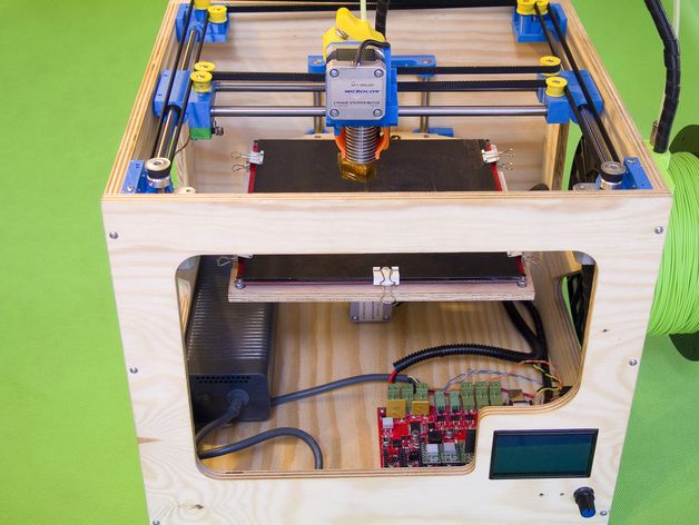 The essence of this technology lies in the fact that it does not have positioning along the X, Y and Z axes. The position of the extruder is set by the angle and radius. The platform of polar 3D printers is round in shape, it moves only along the horizontal axis and only rotates in a circle. The extruder moves up and down.
The advantages of 3D printers based on polar kinematics are:
- the ability to create large objects;
- high energy efficiency;
- material savings;
- small dimensions.
But there are also disadvantages:
- low printing accuracy, which was started by Polar representatives;
- platform does not warm up during operation;
- material restrictions - ABS plastic cannot be processed.
Polar printers are less accurate than Cartesian and Delta printers. The manufacturer recommends using such models for educational purposes; they are not yet suitable for professional printing.
Printing example shows that accuracy cannot be achieved. All features are blurred, the figure lacks sharpness and clarity.
With robotic arms
Printers with robotic arms are a design with a mechanically programmable extruder gripper arm. This is a multifunctional robot: it can carry out welding, painting, milling, etc.
The extruder can move in different directions: in layers, along complex paths in three dimensions, at different angles. Thanks to this set of functions, it is possible to create complex structures.
The main advantages are:
- versatility: the device can perform several types of tasks when replacing the extruder;
- are suitable for industrial applications: you can print large objects with virtually no size restrictions.
But there are also disadvantages:
- low accuracy: such equipment is inferior to Cartesian kinematics;
- large size: devices take up a lot of work surface space.
These models are not suitable for professional 3D printing. They can be considered as an object for a hobby or a tool for it. For industrial purposes, such devices work only when high precision in the execution of parts is unimportant.
SCARA
SCARA (Selective Compliance Articulated Robot Arm) is a kinematics based on horizontal rotation of the platform. The movement is achieved by the articulation of the linkage mechanism.
These instruments are highly accurate and repeatable, and operate with a minimum of noise and vibration. SCARA also surpassed the Cartesian models in terms of processing detail: the difference is that the former work noticeably faster.
Advantages of such kinematics:
- print accuracy;
- high workpiece processing speed;
- small dimensions and weight.
But there are also disadvantages:
- stiffness restrictions in the area of the X and Y axes;
- high cost;
- is not the widest area of use.

SCARA kinematic devices are devices that combine the functions of a 3D printer and a manipulator. Device actions are programmed through software or an installed mobile application.
The choice of kinematics for 3D printers depends on the requirements for technology and application.
- Cartesian kinematic models remain the most common. They combine high accuracy, good speed, small dimensions. They can be used for amateur 3D printing. They work in a Cartesian coordinate system, the platform and the extruder move along the X, Y, Z axes.
- CoreXY and H-Bot are varieties of Cartesian kinematics. They are highly detailed blanks, suitable for professional use. Their disadvantage is the complexity in the process of operation. The user must constantly ensure that the belts do not come into contact with foreign objects and are well tensioned.
- Delta printers are uncommon models whose weak point is print accuracy. In the process of working with the device, there are problems with calibration, as well as with the choice of extruder.

Learn more