3D scanner stl file
How to Use 3D Scanning and 3D Printing for Reverse Engineering
Reverse engineering is a powerful way to create digital designs from a physical part, and can be a valuable tool in your prototyping toolkit alongside technologies like 3D scanning and 3D printing.
3D scanners measure complex objects very quickly, and can speed up your design workflow tremendously when real-life references are involved. With the ability to capture and modify physical shapes, you can design 3D printed parts that fit perfectly on existing products of all kinds. 3D printed jigs allow you to repeatedly locate a drill or saw, or assemble parts precisely with adhesive. Create close-fitting, reusable masks for sandblasting, painting, or etching.
In this post, we’ll walk through the step-by-step reverse engineering process for an aftermarket digital gauge and explain how to scan a part for 3D printing, with tips along the way for using the right reverse engineering tools, from CAD software to to 3D scanners and 3D printers.
For a full breakdown of 3D scanning workflows and technologies, download our white paper.
Download the White Paper
Looking for a 3D scanner for your 3D printer? Read our detailed guide on choosing the best 3D scanner to use with your 3D printer.
One of the biggest challenges people encounter when converting physical objects to digital is a major incompatibility between two different types of 3D models: meshes and solids.
A 3D scanner outputs a mesh, rather than a constructive “solid” model. Meshes need to be reverse engineered to be made editable.
Meshes are the main output of all 3D scanners, and the format commonly understood by 3D printers (STLs). A mesh represents the surface of a shape with a large number of triangles, connected edge to edge. Mesh models don’t contain any information about the object, besides the position of the triangles that define the shape.
On the other hand, engineers are trained to work with solid models. Solid models hold information about how an object is designed, and this information is explicitly encoded into the model as features in a ‘stack’ of logical steps. In solid CAD, it’s possible to change the dimensions for a single feature, and the rest of the model will update to accommodate the change.
Since meshes lack information about the construction of the object, the ways you can alter a mesh model are limited—CAD software like Solidworks and Onshape can’t directly modify meshes. If you need to make major modifications to the underlying design of a scanned part, the mesh needs to be converted to a solid CAD drawing: this process is reverse engineering.
Reverse engineering is important when you want to create new parts that reference or incorporate older designs, where the original CAD design isn’t accessible.
For example, you can create replacement parts that match the original design of damaged existing pieces, or use reverse engineering processes to integrate complex surfaces from existing objects into 3D printable jigs, which are useful when modifying mass manufactured and handcrafted products.
To demonstrate the basic steps in a reverse engineering workflow, let's take a look at the process for creating an assembly jig for an aftermarket digital gauge that fits onto the air vent of a Volkswagen Golf.
Spray coat the object with a temporary matte powder to improve scan accuracy. Even slightly glossy surfaces tend to degrade scan quality, while reflective and transparent surfaces cannot be scanned at all without a matte coating.
Use a temporary matte powder to improve the scan accuracy of your object.
Use a high accuracy 3D scanner to capture the important sections of the part. Tabletop structure light or laser scanners are the right tools for the job, with accuracy of ±100 or better.
Learn more about how to choose the right 3D scanner for your application in our 3D scanning white paper:
Note: You may need to orient and re-scan your object several times if the object has deep recesses.
Some scanners produce extremely large mesh files, which will make later steps grind to a halt.
Scanner software repairs small gaps and simplifies the scan, making the data more manageable in CAD. Try to reduce the model as much as possible without destroying important details.
Tip: If you need more control, Meshmixer is a great choice for refining scanned meshes.
Import the mesh into CAD software equipped with reverse engineering tools. Geomagic for Solidworks is a powerful choice for resurfacing complex, organic shapes.
If you are reverse engineering a part with simpler flat surfaces, Xtract3D is a less expensive, lightweight alternative.
In this step, move and rotate the scan mesh into alignment with any existing design components.
Tip: Make drawing easier by rotating and aligning your scan to face the orthographic view directions.
There are three paths to extract the shape of the scan in order to create a solid model that is editable with CAD tools: semi-automatic surfacing, automatic surfacing, and manual redrawing.
Semi-automatic surfacing
Complex curved surfaces are difficult to manually draw, so you may choose to use semi-automatic surfacing. This function generates surfaces that fit to detected regions of the scan. By varying the sensitivity of the surface detection function, different surfaces will be found.
Tip: Geomagic for Solidworks detects surfaces on the scan to fit 3D curves. Use a “brush” to manually add or subtract areas on the scan from each region.
You may need to repeat this process several times with different sensitivity settings to detect all your surfaces. These surfaces can then be trimmed and knit together to create an editable solid.
Use semi-automatic surfacing to re-create curved shapes when you want maximum editability later on, and when sharp edge accuracy is important.
The re-surfaced result, after trimming.
Automatic surfacing generates a solid model from any watertight scan. You can use standard CAD tools to subtract and add to this auto-surfaced body, but it will be more difficult to move basic features around on the body itself.
You may not need control over edge placement. For example, if you are scanning a part of the human body to create custom ergonomically-shaped products, or want to create a jig to precisely or repeatably modify a handmade object. In these cases, automatic surfacing is a great way to save modeling time.
Note: Compare the results of a automatic surfacing to semi-automatic surfacing: some accuracy is lost, especially around sharp edges.
For simple features such as bosses, holes, and pockets, it’s usually fastest and most accurate to redraw the features using the scan model as a reference. Reverse engineering software allows you to create sketch planes aligned with flat surfaces on the scan and to extract cross sections from the scan mesh, which helps you match the shape of the original object.
Once the scan has been converted to a solid, it can be subtracted from another solid body to create a jig that securely holds the original part.
The design of the new gauge component also references the dimensions of the scan, using curves extracted with semi-automatic surfacing.
Printing the jig on a Formlabs stereolithography (SLA) 3D printer gives you a high degree of accuracy comparable to the output of engineering-grade 3D scanners. Use Formlabs Rigid 4000 Resin for its strength and precision.
Once these steps are complete, the 3D printed jig is ready to use to assemble the new gauge onto the OEM air vent.
The final 3D printed assembly jig, printed in Rigid 4000 Resin.
3d Scanner App™ on the App Store
Description
3D Scanner App for Mac is a desktop tool for processing photos and videos into 3D models using the power of Photogrammetry. Perfect for 3D Design, CAD, Architecture, Games Assets, AR, VR, XR. Share USDZ models via iMessage to let friends and family see your models in Augmented Reality.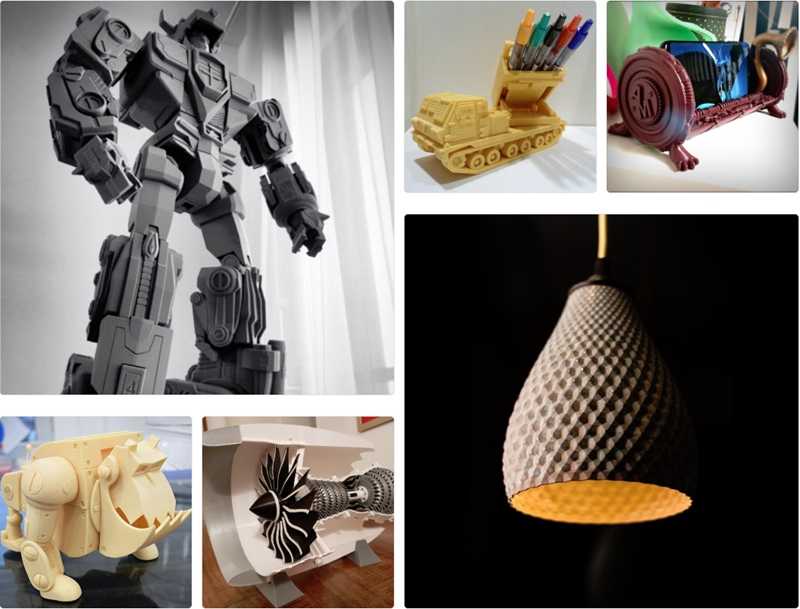
Photogrammetry is done using the new Object Capture API on supported hardware.
Version 1.1.4
ux improvments
Ratings and Reviews
11 Ratings
Amazing!
I was completely unaware of the LiDAR scanning function. I had no idea what it was until today. I was told that my new iPhone 13 Pro has it so I downloaded this app and am amazed at how it works!! I can do so many things with this option now. I am still trying to figure out how to improve my scans and am not sure what is the best way. So, to have some tutorial videos would be a great option.
The only other thing I see with this app is that there are incomplete scans no matter how you do it.There are always holes in places that you have scanned. However, it is minimal when you take into account how great it works!
I would love to be able to take a complete scan of my home without it crashing but it seems too long of a scan does that. So here is an idea for you……….
Maybe you could make an option to scan rooms separately but later be able to assemble them after the separate scans are done. This way we can make models of our complete houses!
Great work on this app! I am so happy with this creation of yours! Keep up the updates and great work! 😊
Love it!!!
Very happy with this app. It is the only one that is fully
Functional and doesn’t require a dang subscription or pay per scan!! I have one suggestion mainly because I cannot figure it out lol. I would absolutely love a way to make the scan data watertight so when I export the STL it will need minimal modification before printing or importing into CAD.For some reason I am not able to get it to function properly in Solidworks (this is not a fault of this app ) which is a bit annoying because my main hope for this is to use it to generate reference geometries that I can model off of. I am certain there is a way to do it but I haven’t quite figured out the process. Nonetheless I absolutely am blown away with this app and it is everything I was hoping for when the iPhone X came out. The 12 pro just makes it perfect!
This is a game changer.
I’ve been using this app to take quick scans of a room and then be able to revisit those scans to pull measurements. I then use those measurements to order material. It is a great way to visualize the room while you are shopping for the materials. I am sure that you can find many other uses for this app. I am not sure if it allows you to import the files into blender, unreal, or any other app like that, but for what i use it for it is golden.
Thank you, please keep up the great work because right now you are the best scanning app I’ve used to date. I would love a decimate feature that would allow us to simplify scans to the most basic geometry, but in an imperfect world you come through perfectly.
The developer, Laan Labs, indicated that the app’s privacy practices may include handling of data as described below. For more information, see the developer’s privacy policy.
Data Not Linked to You
The following data may be collected but it is not linked to your identity:
- Usage Data
- Diagnostics
Privacy practices may vary, for example, based on the features you use or your age. Learn More
Information
- Seller
- Laan Consulting Corp
- Size
- 6.7 MB
- Category
- Utilities
- Age Rating
- 4+
- Copyright
- © 2021 Laan Labs
- Price
- Free
- Developer Website
- App Support
- Privacy Policy
More By This Developer
You Might Also Like
Free STL file 3D scanner
Retractable building plate compatible with Duplo
2. 49 €
49 €
Battery locomotive for wooden rails
€3.99
Level for drilling machine
2.99 €
Another Cube Gear
3.50 €
Vise with metal support
Free
Customizable electronic PCB housing
Free
Finding the center of the cylinder
Free
G - Code - Simulator
Free
The best files for 3D printers in the Tools category
CIRCUIT I BM005
Free
3D printed drill press Table and tube centers
Free
Braille magnetic blocks - a word learning kit
Free
Clarinet Reed Box
3 €
Zheng's GoPro Gubbinses
Free
Y-Axis Layer Shift Test Model
Free
mask hook
Free
DIY 3D Printer Enclosure - Create your own fully customizable enclosure
44. 90 €
90 €
Bestsellers in the Tools category
Filamentmeter
2.83 €
telephone ring holder
0,90 €
UNIVERSAL BED LEVELING INDICATOR FOR VERY ALL PRINTERS
3,22 €
Ender 3 Briss fang Gen2, red lizard, spider, nf crazy, dragonfly, etc.
€1.86
Case for Chill Buddy lighter
1.02 €
Quick print paint bottle holder (6 sizes)
2.86 €
Scissor Paint Rack (Citadel)
5.73 €
PRECISE DIAL INDICATOR 3D PRINT DIY
1.84 €
Cooling system Minimus Hotend
2.56 €
FAST PRINT STACKING STORAGE BOXES STACKING CONTAINERS
€1.50 -fifty% 0. 75 €
75 €
Fire hydrant storage container
2.06 €
Business card embossing system
3 €
well designed: Hemera fan duct
2.50 €
PRECISION CALIPER 3D PRINT DIY
3,02 €
Ratchet holders - magnetic - holders for toolbox organization
2,93 €
PET-Machine, make your own plastic bottle filament at home!
50€ -80% 10 €
Do you want to support Cults?
Do you like Cults and want to help us continue our journey on our own ? Please note that we are a small team of 3 people, so supporting us in maintaining activities and creating future developments is very easy. Here are 4 solutions available to everyone:
-
AD: Disable AdBlock banner blocker and click on our banner ads.
-
AFFILIATION: Shop online with our affiliate links here Amazon.
-
DONATIONS: If you want, you can donate via PayPal here.
-
* INVITE FRIENDS: * Invite your friends, discover the platform and great 3D files shared by the community!
File formats | Prototypster | Online 3D printing service
In order for the model to be suitable for 3D printing, it is necessary to use certain file formats used for specific printers and technologies. This section will guide you on how to choose and save the required file format.
Today, the most commonly used file formats for printing models on 3D printers are .STL (for printing colorless and one-color models) and .WRL (for printing color models). At the same time, you can create models in any convenient and familiar graphic program that supports conversion to . STL, .WRL, etc. files.
Currently our PROTOTYPSTER.RU service supports the following formats of downloadable models, these are STL, PLY, OBJ, 3DS, VRML2/97. However, this does not mean that it is necessary to create models in these formats. The model can be constructed in any 3D modeling program that you are comfortable with and you can export files to the recommended formats for 3D printing. However, there are small, but not always easily solved, problems associated with this.
The first limitation is that 3D printers only support three working file formats. Of these, only two are preferred - these are STL and VRML2 / 97 (.wrl). Other formats can also be uploaded to the site, but in the process of preparing for printing they will be converted into preferred ones. Therefore, in order to avoid unnecessary troubles and errors, try to save the models in the required format immediately during the modeling process.
PLY is a computer file format known as Polygon File Format or Stanford Triangle Format.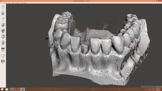 The format is mainly intended for storing 3D data from 3D scanners. It supports a relatively simple description of a single object in the form of flat polygons. In the PLY format, you can save various model properties: color and transparency, surface normals, texture coordinates, and validity of these values. The format allows you to combine different properties of the front and back of the polygon.
3DS - 3D image format used by Autodesk 3D Studio; contains mesh data, material attributes, raster references, anti-aliased group data, viewport configurations, camera positions, and lighting information; may also contain animation data for 3D objects. Consists of blocks or fragments of data, including a description of the identifier and dimension. Data chunks store shapes, lighting, and viewing information, which together make up the 3D view of the model. NOTE: 3DS is an obsolete format, subsequent newer versions of the 3ds Max software use the new . MAX.
OBJ is a geometry description file format developed by Wavefront Technologies for their Advanced Visualizer animation package. The file format is open, has been adopted by other 3D graphics application developers and can be exported/imported to e-Frontier's Poser, Maya, XSI, Blender, MeshLab, Misfit Model 3D, 3D Studio Max and Rhinoceros 3D, Hexagon, CATIA, Newtek Lightwave, Art of Illusion, Modo, Cinema 4D, Zanoza Modeller, etc. Basically, this is a common format.
The OBJ file format is a simple data format that contains only 3D geometry, namely the position of each vertex, the relationship of the texture coordinates to the vertex, the normal for each vertex, and the parameters that create the polygons.
STL (from English stereolithography) is a file format widely used for storing three-dimensional models of objects for use in rapid prototyping technologies, usually by stereolithography. Information about an object is stored as a list of triangular faces that describe its surface, and their normals. The STL file can be text (ASCII) or binary.
Supported by most programs and applications. It is colorless and carries information about the surface of the object. The quality of the surface of the prototyping object depends on the number of polygons that make up the surface.
VRML is a text file format where, for example, vertices and faces of polyhedra can be specified along with surface color, textures, gloss, transparency, and so on. VRML files are usually called worlds and have a .wrl extension (for example: island.wrl). Although VRML files use a text format, they are often compressed using the gzip compression algorithm so that they can be transferred over the network in less time.
The concept of VRML was introduced by Dave Raggett in a paper presented at the First International Conference on the World Wide Web (1994). VRML reached its peak of popularity after the release of VRML 2.0 in 1997, when it was used on some personal pages and websites, mainly for 3D chats. Currently widely used in prototyping for 3D printing.
There are two types of files, VRML and VRML2/97.


