3D printer calibration calculator
3D Printer Calibration - LayerFused
Calibration Overview
3D Printer calibration is critical to 3D printing accuracy. These calculators and resources will allow you to calibrate your printer for optimal results.
Steps per milimeterThe steps per millimeter (steps/mm) calculation is used to calibrate the X, Y, Z and E axis of your 3D printer. This same calculation is used regardless of the axis. The process is to have a known target you are trying to reach and then measure the actual value. The calculator will then adjust your steps/mm based on the measured value to provide a new value which will match the target value.
Current Steps/mm
M503 G-Code will reveal the M92 values. Use your existing X/Y/Z/E value for this field.
Target Value
The expected amount of axis movement. For example, enter 100 if you move the axis 100mm.
Measured Value
The actual amount of axis movement. Use of calipers is recommended, but a metric ruler can be used.
Flow Compensation Flow compensation is used to compensate for the expansion of the filament being pressed against the layer underneath. Use this calculator correct for the expansion of the filament by adjusting the flow rate. To use this calculator print a 20mm x 20mm x 20mm cube in vase mode and then measure the top 5 layers with your caliper. Measure near the center of the cube not near the edges. Enter the values below to see how you can adjust your flow compensation to produce the properly sized line width of extruded material.
Note that flow compensation can differ based on material.
Current Flow %
Most slicers have flow compensation set to 100% by default.
Nozzle Width
Enter the diameter of your nozzle.
Measured Values
Wall 1
Wall 2
Wall 3
Wall 4
Measure the thickness of each side of the cube wall using the top 5 layers near the center of the wall.
The startup code generator creates startup GCode for your 3D Printer. Simply copy and paste the output into your slicers startup gcode settings and you're done.
You can enable a number of features including Bed Leveling, Nozzle Purge and Wipe, Sound Alerts and more.
Printer
Bed Size X
The X size of your 3D Printer Bed in mm
Bed Size Y
The Y size of your 3D Printer Bed in mm
Options
Add Z Auto-Align
Execute a G34 and align the Z axis before homing the printer.
Home Before Printing
Execute a G28 and home the printer before printing. (required for most printers)
Enable Bed Levling
G29 - Adds bed levling, Loads from Mesh 0, Performs mesh tilt before printing to level plane.
Enable KISS Purge
Uses landing strip on your print bed to purge and prime nozzle, wipe tip right before printing. This feature requires a small space on your print bed to have a piece of painters tape on the front of your bed, called a landing strip, for the purge and wipe.
This feature allows you to turn off things like a "Skirt" or purge line that takes up more space on your bed.
Landing Strip Size 15mm X 40mm.
This feature only works on a rectangular print bed.
[See this in action]
Enable Audio Feedback
Adds M300 Audio feedback and a CHARGE! Fanfare when printing begins.
Output
Startup Code
Extruder Calibration Guide (with Calculator) - E Step Calibration
3D Printer Calibration
3DPrintBeginnerApril 14, 2020
19
The extruder calibration is one of the most important process to do for any 3D printer. By doing the extruder calibration, your printer will accurately extrude the exact amount of filament. This translates to much better finish on the printer parts and more accurate dimensions.
Because this process is a bit hard to understand for a beginner, I made an extruder calibration calculator that should make things easier. Only two values need to be entered, and the extruder calibration calculator will take care of the rest.
Without further ado, let’s begin the extruder calibration process.
Why do the Extruder Calibration?
As previously mentioned, by doing the extruder calibration, we make sure that the printer extrudes the exact amount of filament needed. In most of the cases, 3D printers suffer from over-extrusion and sometimes under-extrusion.
When the printer is over-extruding, more filament is being pushed through the nozzle. Because of this, the printed walls look bad, layer lines are uneven and the bottom and top layers.
In the image below, the first cube is before extruder calibration, and the second one is after i calibrated the extruder.
If under-extrusion is present, then you may find holes in the top layers and even in other parts of the print.
Prerequisites for Extruder Calibration
In order to do the extruder calibration, you need to have the following:
- Measuring ruler
- Marker
- Computer with USB cable to connect the printer
- Pronterface
- A bit of patience
For a successful extruder calibration, the hotend needs to be set at the correct temperature according to the filament used. If you are performing the calibration using PLA filament, set a temperature of 195C. If using PETG, set a temperature of 225C.
It’s important to use a temperature close to what you normally use for printing. This ensures that all variables are as close as possible to when you print.
After the hotend reaches the correct temperature, try to push some filament manually. This is especially important to do if you previously printed other materials.
The filament should be easily melted by the hotend. and you should not encounter a lot of resistance when pushing it. The melted filament from the nozzle needs to be a continuous line of filament going down.
If the filament curls to the left or right, there’s a big chance the hotend is partially clogged and you need to fix this before proceeding with the extruder calibration.
Don’t forget that having a good extruder tension is quite important. I strongly recommend performing the Extruder Tension Calibration if your extruder supports this.
How to do the Extruder Calibration?
1. Connect printer to Pronterface
Next step in the extruder calibration process is to connect the printer to the computer via USB cable. Open Pronterface, and choose the correct COM port and Baud Rate. In my case, i used COM4 and 250000.
If you encounter issues when connecting to the printer, make sure you closed all slicers. Cura is known to interfere with the COM ports used by the printer.
2. Get current extruder steps
Enter the M503 command, then press enter. Look for the line starting with M92.
Add the E value in the calculator, then move to the next step.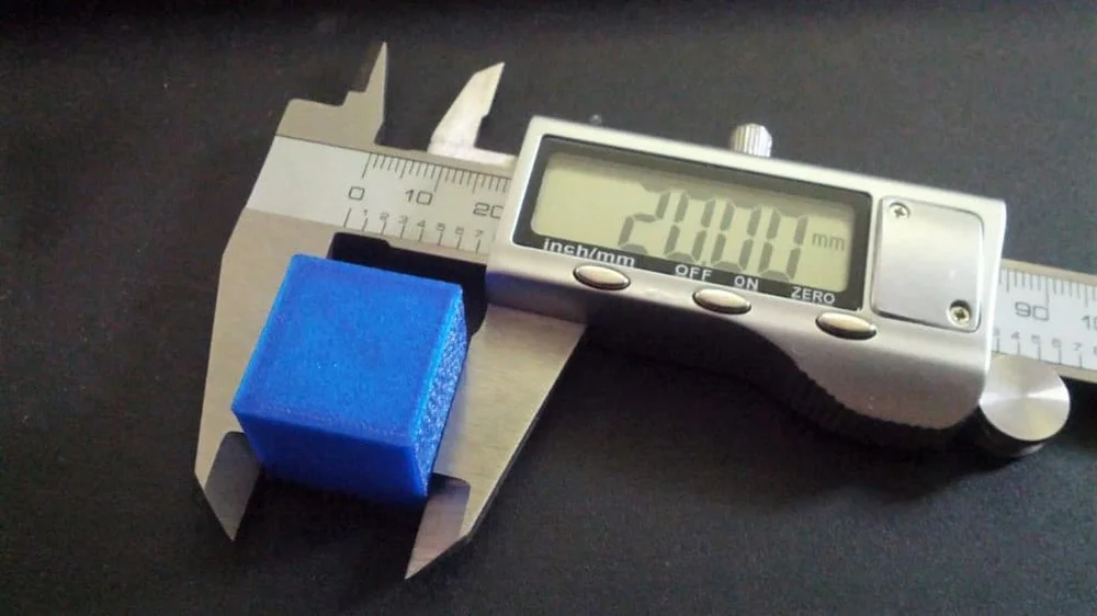
3. Measure 200 mm of filament
Carefully straighten the filament and measure 200 mm from a fixed position. I chose to measure from the end of the PTFE tube that goes into the extruder. Mark the filament, then move to the next step.
4. Extrude 180 mm of filament
Back in Pronterface, run the M83 command for relative mode. Then, run the G1 F100 E180 command. The extruder will start pushing filament and the whole process will take about a minute.
5. Measure the remaining filament
After the extruder stops, measure the remaining amount of filament, and add it to the calculator.
6. Save the new extruder value
In Pronterface, run the M92 Exxx.xx command, and replace the xxx.xx with the value from the calculator, then save everything with the M500 command.
It is recommended to repeat the process in order to make sure the new extruder value is correct.
Please clear your browser cache and refresh the page if the calculator does not show up.
Wrapping Up
The extruder calibration process is now complete. A few things to keep in mind:
- While other guides recommend doing this by extruding 100 mm of filament, after multiple trials I found out that a longer is a bit more accurate. Besides that, it’s easier for me to measure a longer filament section.
- Make sure the pressure on the filament is not changed after calibrating the extruder. If you tighten the extruder lever, and apply more pressure on it, the extrusion can change slightly, and it will influence the end results.
- The spool holder can influence the extrusion quality. If possible, ensure that the spool is spinning smoothly, with a small amount of resistance to prevent tangles.
- If you can’t edit the EEPROM of the printer, the M92 Exxx.xx command that includes the calibrated extruder value can be added in the start gcode of your slicer. This way, the extruder value will be loaded each time you start a new print.

- You can also calibrate your extruder from IdeaMaker without the need of doing modifications to your EEPROM.
It is recommended to also perform the Flow Rate Calibration to fine-tune the layer width and improve accuracy of your prints.
If after calibration, your extruder is still not performing well, check out my Ultimate 3D Printer Upgrade Purchase Guide where I shared a few extruders that may improve your print quality.
You can also join the 3DPrintBeginner Forum where there’s a dedicated category for FDM 3D printers.
Liked it?Consider supporting 3DPrintBeginner if this content helped. You can also join Patreon for exclusive perks! |
Related Articles
3D printer calibration utility
Good afternoon.
I would like to present you a small utility for calibrating 3D printers.
I originally wrote it for myself, but now I decided to post it for public access, maybe it will be useful to someone.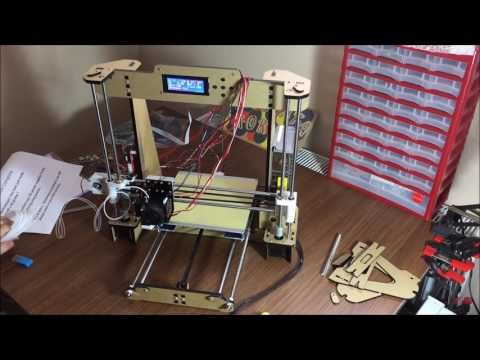
The program is free, but if anyone wants to thank the author, there is a special button :)
First, what this utility can do.
1. Automatic formation of a temperature column. You set only the temperature of the initial, final, step. The program itself substitutes these values into the column.
2. Bar feed calibration. The program itself calculates the required coefficients and saves them in the EEPROM of the board.
3. Table calibration, with automatic zero recalculation and saving in EEPROM.
4. Plastic consumption calculator - mutual conversion of plastic in terms of length, diameter, density and weight.
5. Well, the program has a terminal for manually sending commands to the printer.
The operation of the program directly related to communication with the printer was tested on the Marlin-1.1.x firmware.
Work on other firmware is possible, but not guaranteed.
How it all works below in this post.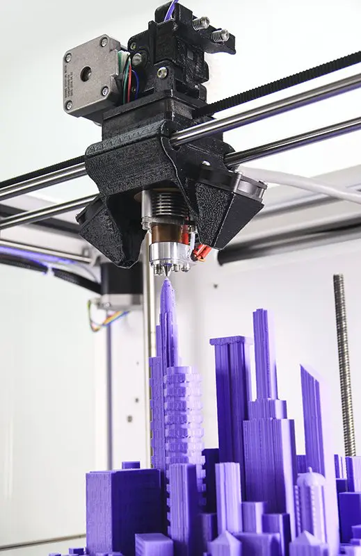
Let's start with the temperature column.
As you know, different plastics have different optimum operating temperatures. To search for them, different methods are used, including printing temperature columns - hollow models in vase mode, with temperature changes, for example, every 10 mm. Then the resulting column is studied visually for defects, bubbles and mechanically for destruction, as a result of which the optimal temperature for using this particular plastic instance is determined.
Usually such pillars are formed by hand by editing the finished G code by inserting commands to change the nozzle temperature at certain intervals.
The work is not complicated, but it can be automated, which this utility successfully copes with:
On the tab /Plastic temperature/ there are three fields in the upper left where you enter the initial temperature for the test, the final temperature and the temperature change step.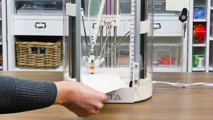
By pressing the /Process file/ button, you select a temperature column at least 10 cm long, sliced in the vase mode. For convenience, I prepared such a column, you can open it with the /Open STL/ button and peel it off.
After processing, a file will be generated with the name: FileName_(TempStart-TempEnd-Step).gcode.
Example:
Temperature column_(260-190-10).gcode.
It will contain the temperature change every 10 mm with the specified step and range, in addition, it will be cut according to the specified range, it remains only to print it.
Bar feed calibration.
A common task, especially for beginners. This utility allows you to automate this process.
On the /Bar Feed/ tab, press the /Pass plastic/ button, having previously connected to the printer (the /Connect/ button on the right) and warming up the nozzle. After feeding, you need to measure how much the bar actually stretched, insert this value in the field next to the /Really stretched/ button, press it. The program itself will recalculate the feed rate, send a command to change this rate to the printer. You can repeat this operation again to make sure that everything is fine, or you can immediately save this coefficient in EEPROM by pressing the appropriate button.
Table calibration.
This task also causes some stupor in beginners, the program is designed to ease it somewhat. Everything you need is collected on the tab /Calibration of the table/:
Calibration means finding the zero offset of the table and saving it in the EEPROM of the board. Leveling the table with bolts is not included in the program function!
Of course, here you also need to connect to the printer first.
Next, the sequence of actions is as follows.
1. Presses the /Home/ button.
2. Select the step with which we will move the Z axis.
3. Use the arrows on the keyboard to shift the nozzle and the table to a distance that we consider to be the zero of the table.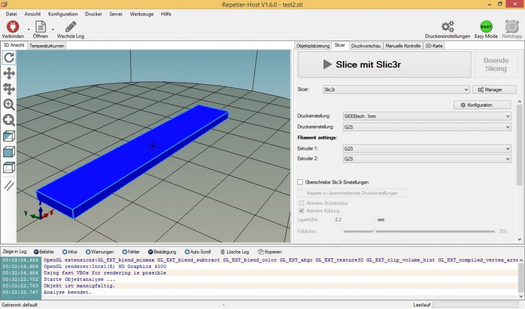
4. Press the button /This is zero/.
5. Check if necessary.
6. Save to EEPROM.
Plastic calculation.
On the corresponding tab there is a calculator for the mutual conversion of plastic in terms of length, diameter, density and weight. Enter the known values and click the /Calculate/ button next to the field whose value you want to calculate.
Printer connection.
Everything here is about the same as in all other printer management programs.
Select the COM port, speed, press the /Connect/ button, the history of data exchange with the printer will appear in the large window: This field saves the history of commands and they can be re-selected by clicking the triangle on the right side of this field.
General.
Settings in the program, including text in large text fields, in which you can write any comments yourself, are saved automatically when you close the program, or by pressing the button at the bottom, in the center of the program window.
There is also a red button next to it, which you can use if the program turned out to be useful to you :)
This button is for quickly transferring any amount from a card, mobile phone account, Yandex Money account.
The transfer is carried out on the Yandex Money website, so your payment data will be protected by this system.
Link to the utility archive.
3DPrinterTool.zip The program does not require installation, just unpack the archive.
manual table calibration using Escher calculator (Escher 3D)
Technician
Hi all.
And again about the calibration of delta printers.
I describe my calibration experience for firmware Smoothieware ,
but I think that it will also work for marlin / repeaters.
(Sorry if there has already been such a topic.)
Let's start -
Calibrate the plane of the table using Escher's calculator.
(the method is suitable even if you do not have a Z-probe)
0.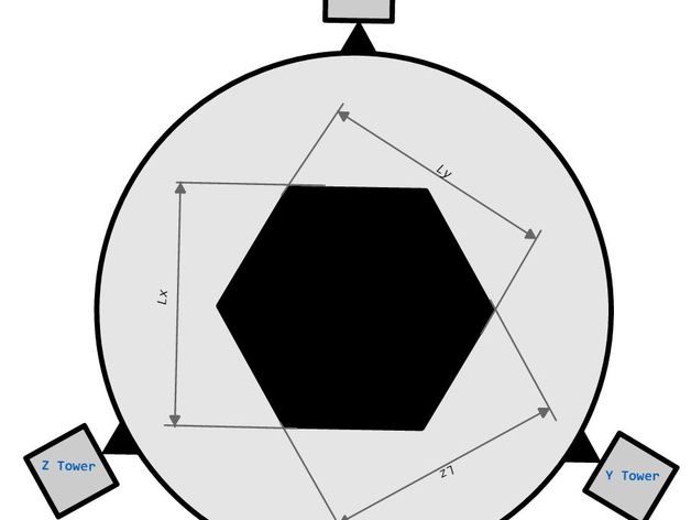 Initially, we assume that we already have a table 0. If not, then calibrate zero -
G28, lower the nozzle onto the table, M306 Z0, M500
1. Open the calculator at - http://escher3d.com/pages/wizards/wizarddelta.php 2. Launch the printer terminal.
3. M500
4. M501 (display: /sd/config-override)
5. select Firmware type: Smoothieware in the calculator.
Steps/mm (for Repetier only) : - do not touch
then enter the data from the terminal taken from config-override:
6. Initial endstop corrections : - take from the terminal
;Trim (mm):
M666 X0.230 Y-1.490 Z1.250
.0000 B0.0000 C0.0000 D0.2800 E0.5700 H0.0000 L371.3400 R189.3200
M665 A0.0000 B0.0000 C0.0000 D0.2800 E0.5700 H0.0000 L371.3400 R189.3200
9. Initial Homed Height : - We take from the terminal
; Max Z
M665 Z383.870 - Initial Tower PoSition Corin ;Optional arm solution specific settings:
M665 A0. 0000 B0.0000 C0.0000 D0.2800 E0.5700 H0.0000 L371.3400 R189.3200
11. Printable1 bed radius 900 table, is not a diameter!
12. Number of probe points : - 7 (set 7)
13. Number of factors to calibrate : - 7 (set ends 7) - put a tick.
15. click suggest probe points - and see the generated coordinates of 7 points.
16. Then repeat the procedure for each and 7 points
G28
G0 Z50
G0 X(point coordinate) Y(point coordinate)
G0 Z3
then manually by 0.01 we lower the nozzle in Z step by step onto the paper on the table to the desired gap.
received value !INVENT! and enter into Nozzle height error :
i.e. if you get 0.1 then enter -0.1, and if you get -0.8 then enter 0.8
and then move on to the next point (p. 16)
17. So for all points we typed in Nozzle height error and now click Calculate
18.