3D printer aluminum casting
Introduction to Metal Casting and Ways to Combine 3D Printing With Casting Workflows
Metal casting is an age-old metalworking process in which molten metal cools and solidifies in a mold to form metal parts. Despite its ancient roots, metal casting is still one of the most popular processes for companies looking to produce metal parts.
This article will cover what metal casting is, how it works, and walks you through the most common metal casting processes and the benefits manufacturers can attain by combining modern digital tools like 3D printing with traditional casting workflows.
White Paper
Get design guidelines for creating 3D printed patterns, walk through the step-by-step direct investment casting process, and explore guidelines for indirect investment casting and sand casting.
Download the White Paper
Metal casting step-by-step from the original design through final casting.
Since the advent of metal casting, the methods have evolved and varied. Its core techniques, however, have remained constant. Here is a general step-by-step process for metal casting:
Ring patterns 3D printed in Castable Wax 40 Resin.
In order to begin the metal casting process, a manufacturer first must develop a representation of the desired pattern. This pattern is essential in designing the mold used for the cast. It is traditionally made from wood, foam, plastic, or wax and ensures that the mold accurately produces the finished metal part. Today, 3D printing is also a common method to produce patterns, which allows designers to create accurate patterns directly from digital CAD software tools.
A pattern is not an exact replica of the desired part. It has additional elements that make the casting process possible, including gates that allow molten metal to flow at a steady rate and vents for gas to escape. Additionally, patterns are also larger than the parts they represent to account for the shrinkage that occurs during cooling.
When the casting piece is hollow, the manufacturer also creates a core of sand or metal to shape the internal form.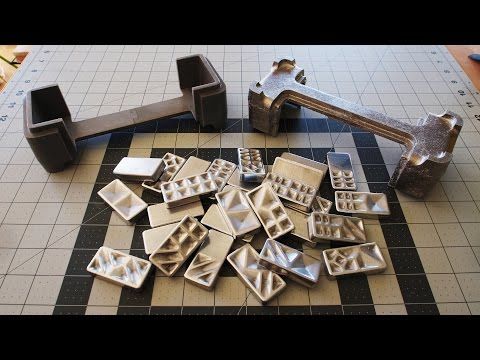 This core gets removed upon completion of the casting.
The next step is creating a casting mold, which can be either reusable (non-expendable) or non-reusable (expendable). Non-reusable molds are usually made out of sand, plaster, wax, or by 3D printing, and just as the name suggests, they get destroyed in the casting process. Reusable molds are made out of metal and other durable materials and can be reused for multiple casting cycles.
Ceramic shells after burnout and 3D printed patterns in Clear Resin.
Molten pewter poured into a High Temp Resin 3D printed mold for metal casting.
During this step, the metal gets heated in a furnace until it melts. Depending on the application, manufacturers can use a variety of different metals, with the most commonly cast metals being iron, aluminum, aluminum alloy, steel, copper, and zinc, as well as precious metals like gold and silver. Once the metal melts, the manufacturer pours it into the mold cavity and allows it to cool and solidify.
Metal casting post-production.
Once the metal cools down and solidifies, the parts get removed from the mold. Depending on the mold type, this can be done by vibrations in a shakeout process, washing away the investment material, or by ejector pins. Then, excess material, such as vents, gates, and feeders, are removed from the parts. Finally, the parts get filed, grated, machined, or sandblasted to smooth the surface and reach the final shape requirements.
Though all metal casting techniques share the same core process, there are various methods better suited for different applications. Some of the most common methods include die casting, investment casting, and sand casting.
Die casting uses a steel mold and high pressure. (Source: buhlergroup.com)
Die casting is a metal casting process in which a manufacturer pushes molten metal into a steel mold cavity at a high pressure to quickly produce metal parts. In die casting, the manufacturer fixes two halves of a die or reusable mold together and uses a nozzle to inject pressurized molten metal into the die.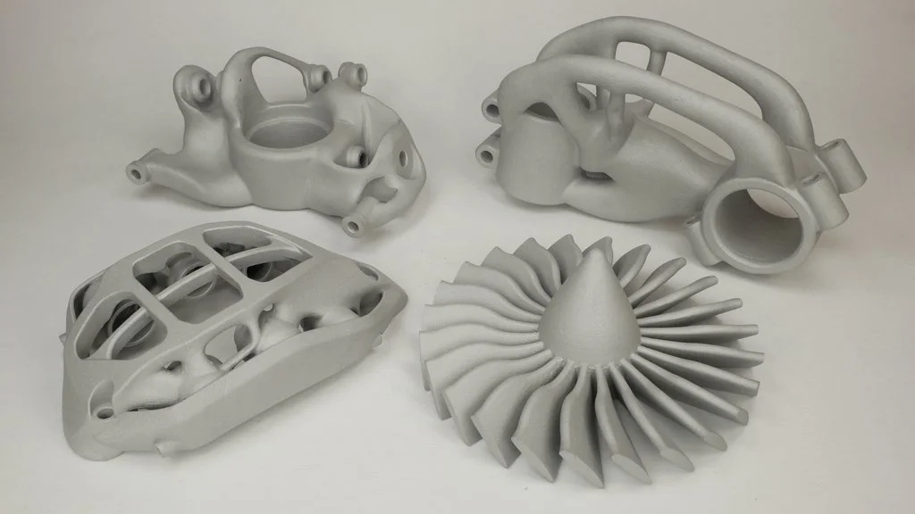 When the metal cools, the die opens, and ejector pins push out the cast.
The two most common die casting processes are hot-chamber and cold-chamber casting. While the specifics of these processes vary, there are several shared characteristics of the die casting process as a whole.
Hot-chamber die casting is the most common of the two main die casting processes. Hot-chamber die casting machines have a built-in furnace to heat the metal within the machine. Once the metal reaches a molten state, the machine lowers a cylindrical chamber into the molten metal. The gooseneck shape of the metal injection system allows the chamber to quickly fill itself, and then push the material into the mold with air pressure or a piston.
Immersing the injection mechanism to fill it allows for rapid and streamlined mold injection in this casting process. Because the chamber is subject to direct heat from the molten metal, however, hot-chamber die casting systems are at risk for corrosion, making them a less viable option for metals with high melting points.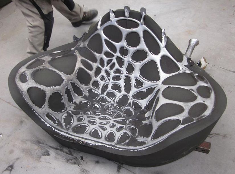 Instead, it is better suited for materials with low melting points and high fluidity, like lead, magnesium, zinc, and copper.
By contrast, the cold-chamber die casting process works more slowly to avoid corrosion. With this method, a foundry worker ladles molten metal into the injection system. A piston then pushes the metal into the mold.
This process limits the corrosion that is more common in hot-chamber die casting. It is an ideal option for metals with high melting points, like aluminum and aluminum alloy.
The die casting process is rapid and produces highly detailed parts. It is ideal for the production of high volumes of complex parts and can also produce strong parts with smooth surface finishes. Die casting’s capacity to produce a high volume of parts makes it a crucial process in the automotive and aerospace industries.
As die casting tooling and equipment are expensive, this process is not cost-effective for smaller production runs. In addition, the malleability of metals used in the process can impact the complexity of the product.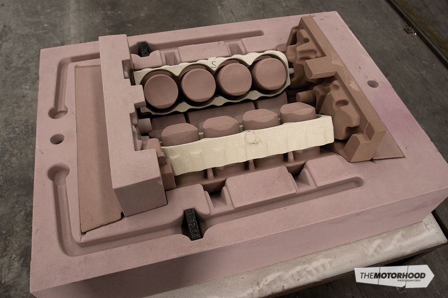
Cast parts from SLA patterns printed in Clear Resin on a Formlabs 3D printer.
Investment casting, also known as lost-wax casting, is a process that uses wax, slurry, and molds to produce complex parts. It is one of the oldest metal casting techniques but is still valued for its ability to create precise metal parts with intricate shapes.
This process is still widely used for producing jewelry, dentistry, and art. Its industrial form, investment casting, is a common way to create precision metal parts in engineering and manufacturing.
Investment casting patterns are typically made out of wax or 3D printed polymers. The patterns are assembled into a tree-like structure and dipped into a slurry of silica, or put into a flask and surrounded by the liquid investment plaster. After the investment material dries, the flask is placed upside down into a kiln, which melts the pattern, leaving a negative cavity in the shape of the original model. Metal is melted and then poured, using gravity or vacuum pressure to pull the metal into the cavity.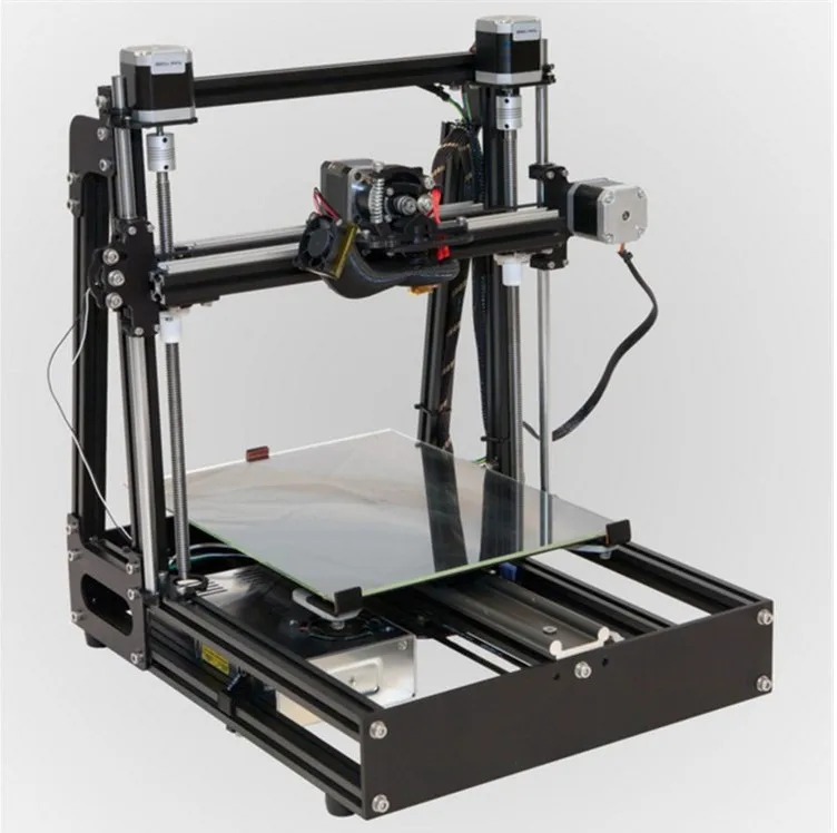 The casted parts are filed, ground, machined, or sandblasted to achieve final geometry and surface finish.
Sprue trees with cast rings.
Investment casting is a versatile process. It allows manufacturers to produce accurate and repeatable parts out of nearly any metal available for casting and complicated shapes that would be difficult or impossible with other casting methods. Casted parts also have excellent surface qualities and low tolerances, with minimal surface finishing or machining required.
These features make investment casting ideal for complex parts in automotive, aerospace, and industrial applications, medical tools, dental implants, as well as fine jewelry and art.
Investment casting is a complex and labor-intensive process. It requires specialized equipment, costly refractories and binders, as well many manual operations to make a mold. It can be difficult to cast parts that require cores and the process is better suited to small parts.
One half of a sand casting mold.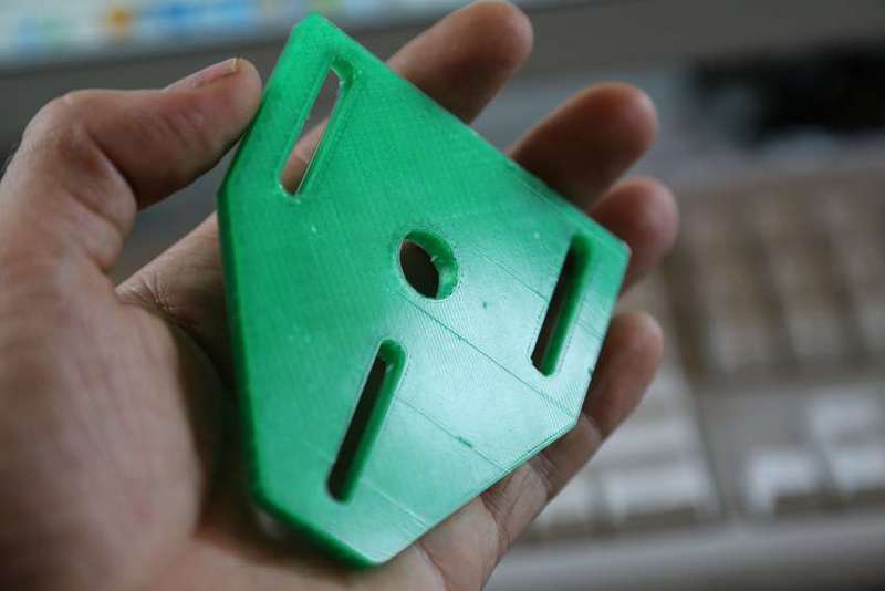
Sand casting is a metal casting method that was first in use 3,000 years ago but remains the most widely used casting method to this day. This process allows manufacturers to cast metal without relying on machining.
In the sand casting process, the manufacturer first creates a foundry pattern, or replica of the casting, most commonly from wood or plastic. The pattern is oversized to allow for shrinkage. Parts with features on one side only require an open-faced mold. For parts with multiple detailed surfaces, the manufacturer separates the foundry pattern into two mold boxes to form a closed cavity mold. The top half is called a cope and the bottom a drag.
Once the manufacturer creates the pattern, they tightly pack sand around the pattern. Then, they add sprues and gates to ensure that the molten metal flows smoothly through the mold cavity. The manufacturer removes the pattern then clamps the two halves of the sand mold together. Once the metal melts to a molten state, it is poured into the mold and left to cool.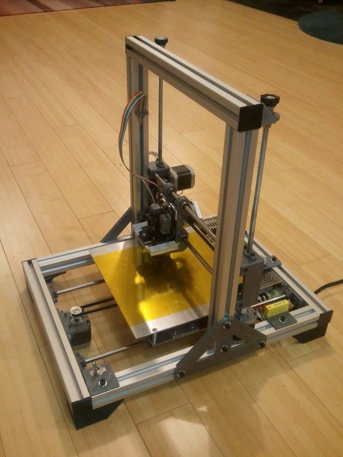 From here, the sand mold is removed using vibrations or high-pressure water. Finally, the manufacturer refines the part by removing sprues and gates, and polishing the cast metal part.
Sand casting is an adaptable process that functions outside the limitations of machinery. Because of this, it can create complex parts of virtually any size. Sand is inexpensive and plentiful, which lowers the setup cost and makes modifications possible. It is the only practical or economical way to produce very large castings. The lead time of sand casting is also short, making it a viable process for short production runs.
Sand casting’s versatility makes it a manufacturing option across a wide array of industries. It can produce medical equipment, automobile parts, electronic equipment, gas tanks, and engine blocks, and more.
Sand casting creates highly porous, textured metals. The shrinkage and rough surface finish also lower the dimensional accuracy of parts. This results in a low-strength final product that requires time-consuming post-processing to achieve a higher quality finish.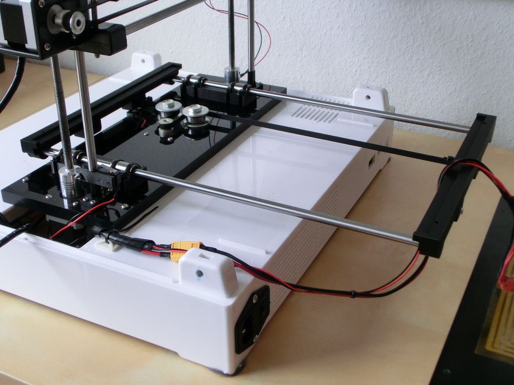
In order to choose the right industrial metal casting process, several factors must be considered. We’ve created this comparison table to help you compare die casting, investment casting, and sand casting in terms of types of metals, production volume, costs, production time, part complexity, and for which industries they are generally used.
| Die Casting | Investment Casting | Sand Casting | |
|---|---|---|---|
| Compatible metals | Aluminum, copper, lead, magnesium, zinc | Most metals | Most metals |
| Production volume | High volume | Low to high volume | One-off to medium volume |
| Unit costs | Low | Moderate to high | Moderate |
| Tooling costs | High | Moderate | Low |
| Cycle time | Rapid | Long | Moderate |
| Industries | Automotive, aerospace, consumer products, furniture, power tools | Automotive, aerospace, jewelry, medicine, dentistry, art | Automotive, aerospace, industrial equipment, electronics, consumer products |
3D printed jewelry ring pattern and cast metal part.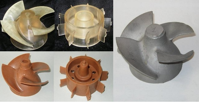
Engineers, designers, jewelers, and hobbyists can capitalize on the speed and flexibility of 3D printing by combining castings processes like indirect investment casting, direct investment casting, pewter casting, and sand casting with 3D printed patterns or casting metal into 3D printed molds. Cast metal parts using 3D printed rapid tooling can be produced in a fraction of the time invested in traditional casting and at a significantly lower cost than metal 3D printing.
Stereolithography (SLA) 3D printers offer high precision and a broad material library that is well-suited for casting workflows and can produce metal parts at a lower cost, with greater design freedom, and in less time than traditional methods.
Webinar
In this webinar, we will look at how desktop stereolithography (SLA) 3D printers are being used to directly print patterns, how to work with SLA patterns for investment casting, and how the benefits of generative design are increasing the demand for printed patterns.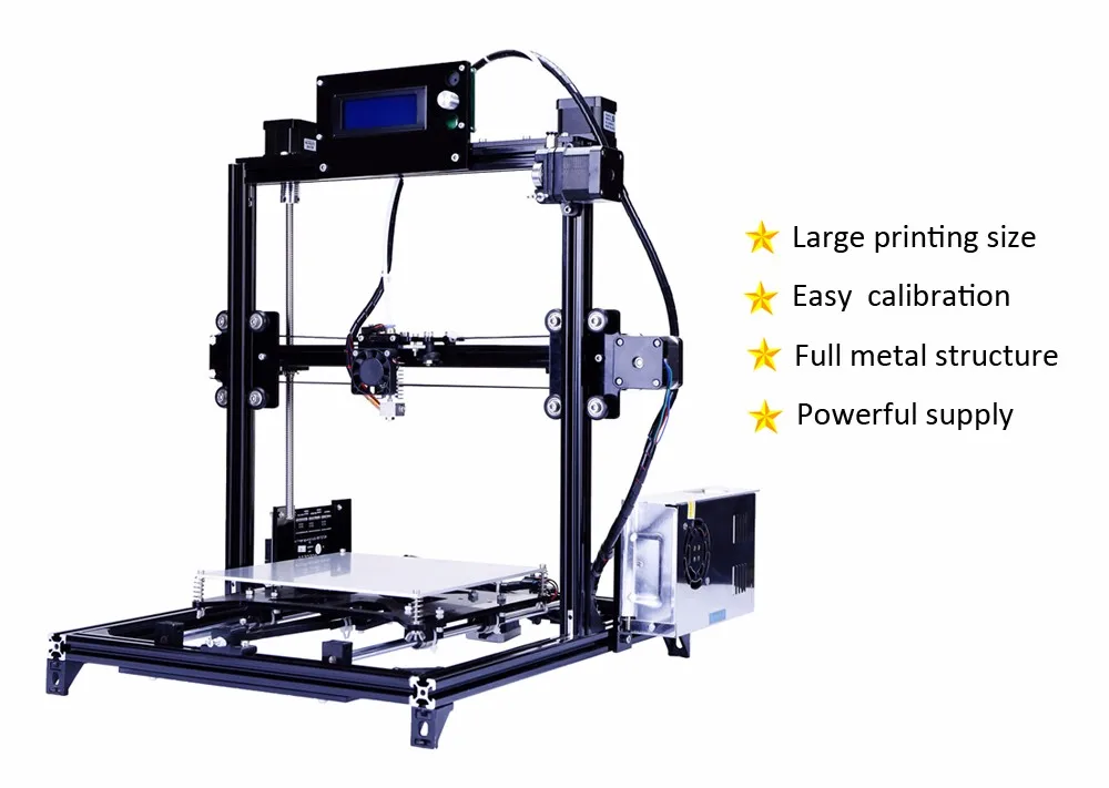
Watch the Webinar Now
A 3D printed mold in Clear Resin for wax injection.
The process of making patterns from molds or tooling is referred to as indirect investment casting because it requires creating molds for producing the patterns in addition to final investment molds.
Rigid molds for wax (often referred to as tools) are commonly fabricated by machining aluminum or steel. Machined metal molds cost thousands of dollars to produce and take weeks of machining and polishing work before first shots can be run and pattern parts evaluated within a casting process.
With 3D printing, manufacturers can directly 3D print the mold for their pattern using materials like High Temp Resin or Rigid 10K Resin, resins with high-temperature resistance. For an optimal surface finish of molded parts, treat the interior surfaces of the mold by sanding and polishing for a smooth look, or bead blasting if a uniform matte look is desired. To ensure the final cast parts are dimensionally accurate, compensate for shrinkage by scaling up the printed mold. The exact shrinkage of the wax and the casting process can be obtained from supplier specifications.
3D printed molds for metal casting shorten the time between concept and first tests to a matter of days because manufacturers can directly print the tooling necessary for running and evaluating parts.
While molded pieces must follow design rules for moldability (e.g., no undercuts, draft is beneficial, etc.), you can achieve increased pattern complexity by using assembly jigs to combine multiple components into a single structure.
White Paper
Download our white paper to learn about six moldmaking processes that are possible with an in-house SLA 3D printer, including injection molding, vacuum forming, silicone molding, and more.
Download the White Paper
3D printed jewelry patterns and metal casted rings.
Direct investment casting is a version of investment casting where the process moves directly from pattern creation to surrounding the pattern with investment material. It is ideal for producing parts with geometries that are too complex to be molded or for parts with extensive undercuts and fine surface texture details, where molding is possible but carries high tooling costs.
Traditionally, patterns for direct investment casting are carved by hand or machined if the part is a one-off or expected to be only a handful of units. With 3D printing, however, manufacturers can directly print the patterns, removing the design and time constraints common in other processes.
With 3D printing, engineers, designers, and jewelers can direct 3D print patterns in order to achieve shorter lead times and geometric freedom that exceeds the design for manufacturability constraints of molding processes. Formlabs developed a range of castable materials suitable for direct investment casting, in particular for the jewelry industry.
White Paper
The way jewelers work is changing, and castable photopolymer resins are leading the way.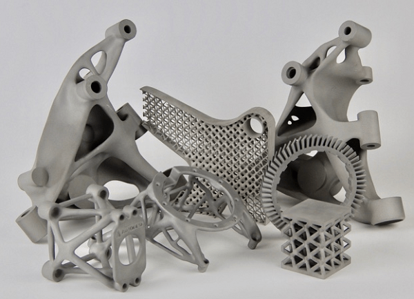 In this guide, learn how to cast fine jewelry pieces 3D printed on Formlabs printers.
Download the White Paper
Sample part
See and feel Formlabs quality firsthand. We’ll ship a free sample part to your office.
Request a Free Sample Part
Grey Resin printed pattern and finished aluminum casting from an open-faced sand mold.
Similar to investment casting, 3D printing can be used to create patterns for sand casting.
In comparison to traditional materials like wood, 3D printing allows manufacturers to create complex shapes and go straight from digital design to casting.
Metal Miniatures made with pewter casting and 3D printing.
Pewter is a malleable metal alloy with a low melting point that can be used for making fully metal objects for decorative applications such as detailed metal miniatures, jewelry, scale models, and replicas of antiques.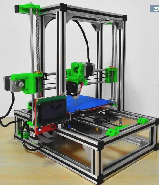
With recent developments in temperature-resistant 3D printing materials, like High Temp Resin for Formlabs SLA 3D printers, it’s now possible to 3D print molds for direct pewter casting.
There are two options for mold designs: a sacrificial or pull-apart mold. In a sacrificial mold, there is a shell designed to be broken apart in the process. Pull-apart molds function with separate halves so the mold can be reused.
Compared to directly printing metal, the casting pewter in 3D printed molds offers significantly better detail and surface finish at a small fraction of the cost. Compared to wax casting, directly 3D printing a mold has fewer steps and requires less manual effort, while preserving the most possible detail.
Webinar
Watch our webinar to learn how moldmaking using 3D printed masters and reusable or sacrificial molds can allow you to produce parts in porcelain, precious and non-precious metals, silicone and biocompatible flexible materials, and more.
Watch the Webinar Now
Jewelry investment casting process with 3D printed patterns.
Businesses looking to boost design freedom or cut costs and lead times have a strong solution in metal casting with 3D printing.
Certain types of complex metal castings, such as large shapes with cross-sections and pieces with multiple cores, are difficult to create using traditional metal casting methods. 3D printing allows manufacturers to produce these complex designs. For example, jewelers can create intricate and custom designs that might be impossible without a 3D printed pattern.
3D printing also eliminates reliance on multiple machines or service providers to create parts. Instead, companies just need a digital file, a 3D printer, and printing material. This can cut costs and waste, as all the material used goes into the final product.
Finally, the combination of 3D printing with metal casting can cut costs and lead time.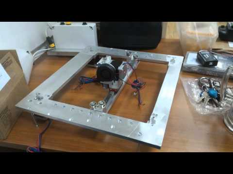 Rather than waiting weeks for expensive tooling before being able to cast a final product, a 3D printer can create a pattern or mold in hours.
Metal casting combined with 3D printing help companies quickly and efficiently create metal parts. With a Formlabs SLA 3D printer, you can expedite the metal casting process and cut costs along the way.
Learn more about the Form 3 desktop SLA 3D printer and request a free sample part to evaluate the quality firsthand.
See the Form 3Request a Free Sample Part
How Do 3D Printed Molds Stack Against Traditional Sand Casting Molds? - 3DPrint.com
Aluminum alloys feature low density, as well as good corrosion resistance and mechanical properties, which is why casting them is an oft-used manufacturing technique. But, defects in molded parts is still an issue. A team of researchers from the University of León published a paper about their work performing a comparative analysis between producing aluminum parts using a 3D printed mold versus the traditional sand casting method.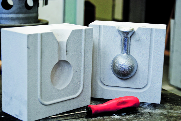
In sand casting, molds are created by compacting sand around a pattern in a mold box; then, the pattern is pulled out and a cavity in its shape is left. Molten metal is then poured into the cavity to produce components. Reducing porosity, improving the microstructure, and controlling dimensional quality and defects are the three most common issues in casting, but using a properly designed mold can help.
“The manufacturing cost of a mould with complex geometry is one of the main limitations in developing it. However, AM allows the modelling of complex designs, avoiding this limitation,” the researchers explained.
Ceramics 3D printing, based on binder jetting, is “the most suitable for manufacturing cores and inserts” for molds. But most research has only focused on specific parameters, which is why this team focused on how feasible it truly is to 3D print a ceramic mold, and then compared it to a mold made with traditional sand casting.
“To prove the usefulness of this modern technology, two different moulds for casting were made: the first was made as a traditional sand casting and the second was made using the 3DP technique.
Once the moulds were manufactured, aluminium was poured into them. Then, we analysed the manufacturing time, cooling rate, dimensional deviation, surface quality, surface porosity, and possible defects, comparing both techniques,” they wrote. “With this analysis, we aimed to determine whether the 3DP technique was applicable for aluminium casting, allowing more efficient designs and reducing the cost of production.”
They used an AlSi series casting alloy to design the part, and then designed and calculated the filling system (sprue, well, runner, gates, and riser) for the molds. To study the melt flow’s behavior in order to optimize the filling system, finite element analysis (FEA) was used to simulate filling and solidifying the parts during casting, along with generated turbulence and distribution of the gas entrainment into the liquid. The team used CATIA v5 r21 software to draw a 3D model of the part and both molds, and the molds were then fabricated.
“To manufacture the sand casting mould, a divided pattern was made by the Fused Deposition Modelling (FDM) technique with the Ultimaker 2+ machine,” the team explained.
“The pattern contained the part and the filling system.”
A Projet CJP 660Pro from 3D Systems was used to fabricate the ceramic mold using inkjet technology. The aluminum alloy was poured, the melting process took place, and they measured the temperature of the mold “by a K-type thermal couple localized at 2 mm from the mould cavity.”
“To achieve proper pouring for the sand casting, it was necessary to fix the halves of the moulds. For the 3DP technique, it was necessary to rest the mould on a sand base to prevent movement during the casting. Subsequently, the metal was poured into the different moulds,” the researchers wrote.
“Finally, the aluminum alloy was solidified and the casting was extracted from both moulds by vibration and crumbling. The filling systems were cut, and the parts were cleaned with pressurized air to begin the analysis stage.”
They compared dimensional quality, roughness, porosity, and general defects, using a Breuckmann Smart SCAN3D-HE structural light scanner to analyze them first, and processing the point clouds with Geomagic Control X software. A profilometer measured the surface roughness, and the molded parts were sectioned and polished with a 3-µm diamond paste, then photographed by a Leica Kl 1500 camera, to evaluate internal porosity. ImageJ software from the National Institutes of Health (NIH) was used to analyze the images.
Standard design rules were followed to create the sand mold, which includes a pouring cup and a tapered sprue that ends in a well. But, because of the design freedom that 3D printing brings, that part didn’t need a round geometry to “avoid draft angles” and “obtain a proper pattern removal” without damaging the mold. Additionally, 3D printing allowed the researchers to “optimize the filling system” in the mold.
“Two cylindrical gates were connected to the part cavity,” they wrote. “Due to this improvement, it was possible to eliminate the well and to decrease the dimensions of the filling system, as shown in Figure 2c. The total volume of the 3DP mould was 449 cm3, the metallic yield was 49.
75%, and the weight of the mould was 0.55 kg. Compared to the sand casting, the metallic yield was optimized by 29% and the weight of the mould was 95% lower.”
To avoid metal turbulence, oxide films, and gas entrainment, they had to consider the gating speed, which should be no faster than 0.5 m/s during filling. They found that with the sand mold, the speed in the gate increased quickly once the liquid metal had entered the part cavity, which, due to the fountain effect, caused major turbulence. But, with the 3D printed mold, the filling process was homogenous and gate speed remained constant, since they had been able to add an open riser to the design.
Software was used to measure the gating speed at the ingate area’s cross-section during the filling of both molds, and you can see the varying velocities at the ingate center in the figure below.
The process had four stages:
- A high input speed generated for both techniques, reaching up to 1.
 10 m/s in sand casting and 0.55 m/s in 3DP casting
 - Speed decreased and stayed constant during most of the filling process at around 0.90 m/s in sand casting and around 0.48 m/s in 3DP casting
- The speed kept decreasing to 0.63 m/s in sand casting, but remained constant in 3DP casting
- The speed remained constant for both techniques with regard to previous values, but majorly diminished while completing the filling process
Because of the high speeds in the molds during filling, erosion could generate, causing the affected areas to be ripped away. There’s a higher probability of erosion for sand casting due to the fountain effect, but this decreases with the 3DP mold, because the velocity profile is more easily controlled.
The part then solidifies once the molds have been filled. During filling, the mold temperature went up, and then down during solidification.
“The sand-casting temperature remained uniform in the part cavity at about 710 ◦C,” the team stated.
“However, the 3DP mould temperature was about 675 ◦C. A lower cooling rate was obtained in the sand mould due to the low thermal conductivity of the sand and the greater thickness of the mould. In contrast, the lower thickness and higher thermal conductivity of the 3DP mould facilitated the flow of heat.”
It took 5.24 seconds to fill the sand casting mold and 541 seconds to solidify the part, compared to just 2.20 seconds of filling and 378 seconds for solidification with the 3D printed version.
“A lower solidification time means a faster cooling ratio, resulting in higher productivity and better mechanical properties of castings,” they explained.
Additionally, it only took ten hours to fabricate the 3D printed mold, while the sand casting one took nearly 24 hours, as they had to make a two-part pattern and smooth its surface.
Roughness of the part made with the sand casting mold had a mean value of Ra = 3.70 µm in the layer construction direction and Ra = 4. 53 µm the opposite way, but while the roughness was even lower in the layer construction direction on the 3D printed part, it was Ra = 7.07 µm in the opposite direction, due to the staircase effect we often see in 3D printing.
“With regard to the dimensional precision, while the staircase effect in the surface of the 3DP mould is the most critical aspect to control, in the sand casting mould the critical aspect is the dimensional precision of the pattern,” the researchers wrote.
In analyzing the dimensional quality, the parts were scanned and Geomagic Control X was used again to process the point clouds. There was an average 0.76 mm deviation between the part and the pattern for sand casting, but -0.43 mm for 3D printing, showing that “the 3DP casting technique can manufacture a more precise part than sand casting.”
Finally, the researchers made a longitudinal cut in the parts in order to analyze what had caused the gas entrapment and bifilm porosities in the castings.
“Microstructures of the cross-section of the moulded parts showed folded shapes and air input in sand casting, which could be produced by the severe turbulence and the oxide film present in the melt during the filling process,” the team explained. “On the other hand, the porosity found in parts produced with the 3DP mould corresponds to shrinkage; during the filling process, the remaining binder is vaporized, creating nucleation points. In this way, pores are formed by shrinkage and a mixture of shrinkage and gas entrapment.”
Surface defects were only spotted on the part made with the sand casting mold, and one of them was the sand itself.
“Sand areas were torn off by the metal stream, floated to the surface, and were then trapped by the molten metal. The main cause of this defect was attributed to an uneven compaction of the mould or a high liquid speed capable of damaging the mould,” they wrote.
The researchers concluded that using 3D printing to fabricate aluminum casting molds was feasible and “adequate” as an alternative to sand casting, as it majorly reduces time and allows for the creation of more complex geometries.
Stay up-to-date on all the latest news from the 3D printing industry and receive information and offers from third party vendors.
Tagged with: 3d print ceramics • 3d print molds • 3d printed molds • 3d simulation • aluminum alloy • catia v5 • fea • Finite Element Analysis • Geomagic Control X software • inkjet 3d printing • projet 660pro • Projet CJP 3D printers • research paper • sand casting • ultimaker 2 • University of Leon
Please enable JavaScript to view the comments powered by Disqus.
Casting on models printed on a 3D printer / Sudo Null IT News
Jeshua Lacock writes:
This page describes my first and successful attempt to cast aluminum parts directly from 3D printed PLA models. The process is almost identical to wax casting, but instead of burning the wax, I burned the PLA plastic (bio-plastic)
I needed aluminum parts to mount the focus lens for my 150W CO2 cutting laser. These parts had to be adjustable and had to be mounted on a frame assembled from scrap aluminum found.
I get excited when I think about being able to do it all in one day: concept -> design -> 3D printing -> finished metal casting
Step one - detail design.
I used the amazingly powerful OpenSCAD to quickly develop the parts I needed. OpenSCAD reads the script in its own language to draw the 3D model. In my case, I just drew a shape in Adobe Illustrator and converted it to OpenSCAD format using the Inkscape plugin.
Here is the design of the second piece. I drew two shapes in Illustrator and gave them depth in OpenSCAD. Very fast and easy. Now I have 3D models, it's time to print them!
The process of printing the first part on my Ultimaker (fast shot).
The resulting part is in hand.
Printing the second part.
Second printed part in hand.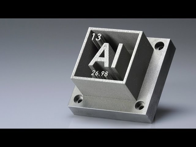
Checking how both parts fit together.
Sprues and air ducts are attached, everything is ready for pouring the molding mass.
Molding mass - 50% fine sand and 50% gypsum.
After adding water and mixing thoroughly, I used a home vacuum food sealer to get rid of air bubbles in the sand.
The second piece is ready to be molded!
The first detail is poured!
The part is completely immersed in the mixture - I hope everything works out.
Both molds are set to dry.
After a couple of hours, I placed the molds in the oven on medium heat.
My new little oven. Heats up quickly for 10 pounds (~4.5kg) or less of molten aluminium. 2 times more when it flares up.
Forms are good and well done. Once heated to about 1200F (650C), the plastic doesn't stand a chance. After removing, I blew out the molds with compressed air to blow out any remaining ash.
The still hot molds are placed in dry sand. It serves several purposes:
- additional support since the molds are quite fragile
- insulates molds and retains heat when cured
- will allow me to install sprue extensions (see below). The expander gives extra pressure to the casting and also acts as a riser that stays molten and provides extra metal while the casting solidifies and contracts
My sprues are just cut aluminum cans. Works great!
After melting aluminum with a small addition of copper in the crucible, removing the slag - it's time to pour!
So cool! It looks like the forms filled out perfectly. Now the hard part is to wait long enough for the metal to cool for me to know if the parts are good or not.
Excellent! The details are straight from the sand, only the sprues and air ducts are cut off.
I cut the center hole with a small 14mm tap. Everything seems to fit together nicely.
I like the details on the casting - you can see all the lines from the 3D printing, their width is only 0.2mm.
The moment of truth - do they fit the frame? YES! I made a plastic part to fit the frame perfectly, then printed it again at 102% size increase. When aluminum cools, it shrinks by exactly 2%.
The center of the black nipple is where the focused CO2 laser beam will come out. Tube - for compressed air to blow off smoke in the path of the laser (the so-called air-assist).
Looks like I can put this to good use!
The black hole in the center is a focusing lens.
I'm so happy that the parts fit the frame perfectly without any additional processing and even without a file!
This is the first test of my laser. Approximately 60% power. Burns wood instantly.
Translator:
Jeshua Lacock has made a wonderful, actually step-by-step guide on how to cast aluminum from 3D printed plastic models. For those interested in the practical aspect, there are many recipes on the site instructables.com on how to make an aluminum casting furnace. Even from a coffee can!
Printed aluminum casting and St. Petersburg Customizing
Application
Subscribe to the author
Subscribe
Don’t want
54
Good day to everyone, before I get down to business, my name is Alexey yourself, because this is the first post on 3DToday.
Since 2014 I've been doing 3D design, engineering, 3D printing, CNC, metalwork, jewelry and some customization. During this time, a lot of experience has accumulated: not only in 3D printing, but also in related technological areas. Perhaps the time has come to share it - this is how the idea of a series of articles about the use of 3D printing as one of the tools in the production chain based on a small workshop was born. The emphasis in these articles will rather not be on WHAT is printed, but on what happened BEFORE and what happened AFTER the printing itself.
In the spring of 2018, not long before the international motorcycle forum IMIS-2018, my friend and colleague, Alexey Cherkasov, shared with me the idea of making a custom cast aluminum intake manifold for his motorcycle. By the way, he has been building this project based on the Yamaha XS650 for half a year and planned to participate in this spring custom event. He had two vintage carburetors from the 60s and 70s: Posa 35 and Lake 35. He planned to put one of them on his bike. Slightly modified by Alexey Lake 35 carburetor:
By the way, the project eventually won first place that year in the "Old School" nomination:
At that time, the engine and the new frame were already modeled in 3D, it remained to draw the trajectories of the air-fuel mixture, landing mounts to the engine, carburetor and general form. The layout of the units in the frame was quite tight, not much to turn around, but nothing too complicated. 3D model of the new manifold:
Manifold assembly with carburetor:
After that, the 3D model of the intake manifold was printed from blue PLA from FD Plast on my FDM printer. After a little processing, a system of beeswax sprues was formed on the plastic model (if you are interested, in the next article I will tell you more technical points) and the model was filled, without vacuum (the mold did not fit in the machine), with Satin Cast 20 gas-permeable molding sand. from PLA: A couple of hours after the mixture has solidified, the mold with the plastic model and sprue system inside is placed in the oven for two hours at a temperature of 731 degrees (recommended temperature for the mixture used). In the process, plastic and wax burn out, the remains in the form of ash after combustion can be blown out of the mold with a compressor. In general, it is better to pour molten metal into a mold that has been preheated evenly in a furnace and installed in a special vacuum casting machine. But due to the absence at that time of a separate melting furnace for metal with a crucible, the furnace was occupied with melting aluminum for the collector, and the mold was heated by a gas burner.
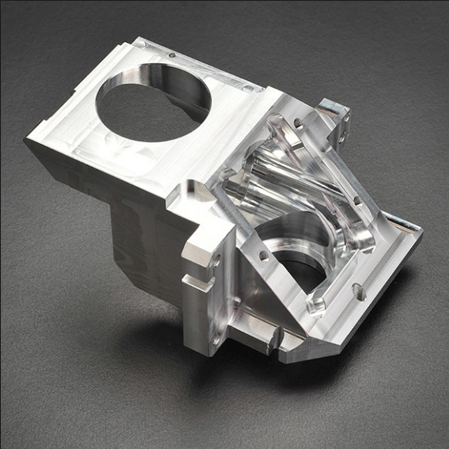 It was also impossible to put a mold into a vacuum casting machine because of the size of the mold itself (the machine is designed for smaller products), so casting was carried out under atmospheric pressure. Immediately after the metal ceases to be red, the mold is lowered into the water, where it dissolves. A photo of the cast product without processing, immediately after being removed from the bucket of water, fragments of sprues are visible: Next, the product was processed, the sprues were removed, the threads were cut, the planes of the flanges were aligned on a milling machine. Manifold with carburetor after installation on a motorcycle:
A couple more images for those interested in the Lake 35 carburettor design:
I'm currently designing and building another intake manifold for two Mikuni carburetors, but this time for a snowmobile. If the article comes in, I will tell you in more detail both about past experience and equipment, and about new experience. This time we will try to cast it in a casting machine, and a separate crucible furnace appeared in the workshop.