3D printed steadicam
95 Steadicam 3D Print Models
3D Models Browser > Steadicam
There are 95 models for printing. Find, store and print the one you like the most!
Reset Filters
95 Models available (0.02s)
Did you mean:
-
steadicam Gadget steadicam
-
steadicam gadgets steadicam
-
steadicam gadgets steadicam
-
steadicam free steadicam
-
steadicam gadgets & electronics steadicam
-
steadicam gimbal camera camera gimbal stabilization steadicam
-
quick release steadicam innorel sp70 dslr steadicam
-
dji gopro steadicam 3d printing dji steadicam
-
steadicam camera
-
2d steadicam sg90 robotics arduino diy mpu6050 sg90 steadicam
-
steadicam improvement ii camera cardan gimbal stabilizer steadicam video
-
dji mavic pro steadicam handle handle dji mavic steadicam
-
steadicam knob camera
-
make steadicam diy
-
gopro steadicam parts
-
smoothee steadicam counterweight clip diy adapter clip counterweight smoothee steadicam
-
steadicam improvement camera camera quick release stabilizer steadicam steadycam video
-
steadicam smoothee gopro mount camera gopro gopro mount smoothee steadicam steadycam
-
steadicam dc camera gimbal
-
mechanical gopro steadicam gadgets
-
gopro steadicam gimbal camera
-
adapter action cameras gopro steadicam actioncam adapter adaptor camera adapter gopro steadicam
-
dslr camera stabilizer maker diy camera stabilizer glidecam steadicam camera gimbal steadicam
-
steadicam smoothee baseplate adapter camera gopro mobile phone tripod mount steadicam tripod mount
-
gopro steadicam gimbal modified camera camera mount gimbal gopro gopro mount steadicam steadycam
-
krotocam-based steadicam handle camera
-
gimbal pins mechanical toys steadicam
-
weight balancer yelangu steadicam camera
-
dji mavic pro steadicam handle camera dji dji mavic pro handle mavic pro steadicam steadycam
Sponsored
Sponsored
Can't find what you are looking for?
Find a professional for your 3D project
Look for the best 3D professional to bring your project to life
Request a 3D Service from a professional
Publish a request with your requirements for a 3D professional
Store and request to print a 3D model list
Create your print list of 3D Models for 3D professional to get a quotation
Print your models or execute your ideas on a safe mode.
▷ iphone steadicam 3d models 【 STLFinder 】
Steadicam
grabcad
Steadicam Camera Stabilizing Systems.
Steadicam
grabcad
Steadicam project. ...By cutting and bending technology
Steadicam
grabcad
Steadicam is a brand of camera stabilizer mounts for motion It mechanically isolates the operator's movement, allowing for a smooth shot, even when the camera moves over an irregular surface.https://www.instagram.com/mile_domanovic/
3dprinted steadicam for gopro, actioncam and iphone
thingiverse
/Daniel Instructions This is a almost all printed steadicam for small cameras like gopro, sony etc.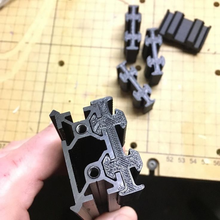 or for mobile phones. It's made for m3 bolts and nuts with 1xF623ZZ ball bearing and one traxxas 5347 ball joint this one needs an m4 bolt about...
steadicam handmade
grabcad
steadicam handmade. ... в дальнейшем я попробую сделать Merlin steadiCAM
Steadicam
myminifactory
https://youtu.be/YwRdFdmOphw https://3dcraft.by/
Steadicam
pinshape
https://3dcraft.by/
steadicam
grabcad
You need to shoot a video. Designed for the camera CANON 5dm2. ...Made was not.
Steadicam Arm
grabcad
Steadicam Arm model, roughed out design. ...This design still requires fine tuning and adjustment in case you decide to download it.
Steadicam Improvement
thingiverse
The Steadicam I use is a widespread chinese model sold under different brand names (Roxant, Viltrox, Easttowest, Afunta, Andoer . . . ). It provides excellent stability and reduces camera vibration during recording assuring smooth videos. Although...
SteadiCam Knob
thingiverse
Two of the plastic heads on some adjustment knobs on our SteadiCam have been broken off for a while, making it hard to tighten things down.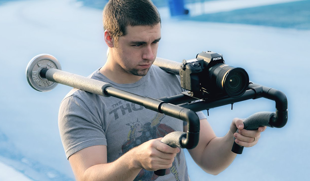 Not having the pieces of the original, I jumped onto ShapeSmith and made up a quick replacement based on the...
steadicam ver.2
grabcad
steadicam ver.2
standard socket female steadicam
grabcad
standard socket female steadicam
Steadicam Free 3D model
cgtrader
Steadicam Camera Stabilizing Systems. ...
Gimbal for steadicam
grabcad
This gimbal for steadicam project
2D steadicam sg90
thingiverse
Simple 2d steadicam based on sg90 servo.![]()
Camera Steadicam For DSLR
3docean
Handheld Video Stabilizer Camera Steadicam Stabilizer for Canon Nikon Sony Camera Gopro Hero Phone DSLR DV
Mechanical GoPro Steadicam
thingiverse
A 3 part steadicam with gimballed joints. ...Primarily designed for a GoPro Hero 3.
Smoothee Steadicam counterweight clip
thingiverse
Simple clip to add counterweight to smoothee steadicam. ...Just insert M6 bolt a add required amount of washers
Iso Arm - Steadicam
grabcad
WIP can't afford a steadicam, hoping to build one instead! ...Many more parts & refinements still to do.
Go Pro steadicam
grabcad
A small, lightweight Steadicam for Go Pro action cameras. Spring is not included in the model. ... Ideal for 3D printing.
Steadicam Smoothee GoPro Mount
thingiverse
I somehow lost the mount for my steadicam. I found the baseplate file but didn't want to have to attach another piece to it to us my gopro.
...
I found the baseplate file but didn't want to have to attach another piece to it to us my gopro.
...
SteadiCam Smartphone Mount
thingiverse
https://cults3d.com/fr/mod%C3%A8le-3d/gadget/steadicam-smartphone-mount FR Accessoire permettant de monter un smartphone sous un steadicam Conçu pour Zhiyun Smoith 4 adaptable pour tout autre model ayant un insert 1/4 sous le manche. testé sur...
steadicam Smartphone Mount
cults3d
two vertical or horizontal positions Supply of STL files and PDF assembly drawing plus bomb EN Accessory for mounting a smartphone under a steadicam Designed for Zhiyun Smoith 4 adaptable for any other model with a 1/4 insert under the handle. ...two...
Steadicam for mobile phone
thingiverse
This is the basic model of steadicam for mobile devices. Robust construction on five industrial bearings. Adjust the width of the phone. The possibility of setting up a stedicam as a professional equipment. ... axis tube 10mm bearing 6000Z 26х10х8...
krotocam-based steadicam handle
thingiverse
The "shove a bearing with some tape around it into a flashlight" approach to making a steadicam handle really sucks, so I designed this handle which places the bearing into the handle and adds a top to it to secure it. .. . I haven't printed this yet,...
Steadicam Improvement (II)
thingiverse
It applies to a widespread steadicam sold under different brand names (Roxant, Viltrox, Easttowest, Afunta, Andoer . . . ). ...I found that the ball head was not so smooth, even oiled as adviced in many forums.So I decided to replace it by a...
Steadicam for DC camera
thingiverse
Steadicam for DC camera Instructions The STL size for this is huge, so I upload my source file in 123D beta 0.9, and for your easy edit. My design is inspired by lots of gimbal / steadicam made by others, can't recall and mention all of them. But I...
GoPro SteadiCam Gimbal modified
thingiverse
I read the description of GoPro SteadiCam Gimbal for Kayak by Soul4sale (https://www.thingiverse.com/thing:2763695) to know how to attach the rod to the GoPro_gimbal_center_v2 I saw he use a tap to create threads in the bottom hole of the center part...
GoPro Steadicam Gimbal
thingiverse
This is a Cheap and easy alternative to GoPro gimbals such as the Steadicam Curve. It uses AUD 10 cent coins as a counterweight, if anyone wants to modify the models to fit different weights or currencies, feel free to do so. I recommend printing the. ..
..
Steadicams on a 3D printer or the "Bulgarian" project
I want to share my project of a steadicam that I have been hatching for several years (since the time when there were no serial steadicams like Osmo or Nibula , or whatever it was). Moreover, this very Nibula, when it appeared, was for a long time the only budget version of a steadic made according to the “one handle” principle, on which you can mount an average mirrorless camera like Sony Nex, and even a small mirror.
At first I didn’t really understand how it would all look like, I took this serial project called 9 as an example0003 Go2 . I did not find links to the store of the latter, but perhaps it can be bought somewhere. Of course, I was worried about the price of Nibula was in the region of half a thousand greens. Go2 cost a little less, despite the fact that it is made for gopro and smartphones. At Go2, I spied on the option of changing the battery, according to the principle of a screwdriver. I found this option interesting.
I must say that before that I had experience with the three-axis carbon steadicam , at first negative (everything broke, twitched and burned). But then quite positive: everything worked, filmed and spun. The controller was EvvGC, and in the end I became friends with him, but at the same time I always looked towards Mos, praised for reliability and functionality. This steadic was inexpensive and impressed with its promise to stabilize a 5D-type DSLR on the ground and in the air. It’s good that I didn’t launch it into the air, because after I crashed it (and this would inevitably happen), I would definitely go into a semi-annual depression.
So, even at pre-crisis prices, I bought Emax GB4006 KV87 and GBM6324 180T motors (for JAV axis) + slipring. And the F07503 ALEXMOS controller (this is the Alibaba designation) with an additional board under the 3rd axis.
After I decided on the approximate image of my stabilizer, I began to look for a case similar to that of the Go2. It turned out to be not an easy thing, nothing ready came across. As a result, I even bought a battery grinder for almost a penny, and have already begun to screw it up and redo it. At the same time, I managed to like her, and at the moments of derban all the time I wanted to leave her as a grinder, which in the end was done, thanks to the experience of 3D printing and 3D modeling, which came very timely.
Bulgarian is now serving faithfully in its almost original form.
I decided to borrow only the battery from this saw. It certainly does not quite fit, because. at 18 volts. And it seems to be too much, great and even heavy. For that, it is lithium-ion, and you can put the entire structure on it vertically.
In general, I began to draw a pen model in SolidWorks. It took a long time, you just have no idea how much. In the process, much improved, finalized, tried different options.
I came to the conclusion that it was more convenient to make it from 3 parts.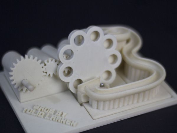 Moreover, the back can be varied depending on the attachment of the battery. I placed a joystick, buttons, a battery charge display (from BEC) and a switch in the back, as well as gopro-type mounts (for additional handles, tripods and external monitors) on the case.
Inside: controller, several power stabilizers (for powering the controller, camera, and smartphone if used as a monitor). I wanted to place a Wi-Fi video transmission module inside, but then thoughts appeared that it was not necessary to output the video to some additional monitor at all, because. a camera monitor will suffice.
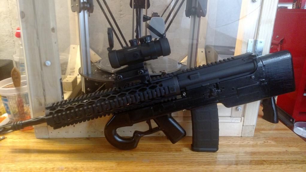
In the meantime, he made friends with the 3D printer because I realized that printing to order in the case of such developments is no longer an option (just a big waste of time). The printer is working, details are being printed.
By this time I have already assembled a pen and printed a frame for a Sony Nex 5R camera. Now I'm thinking how to make 2 levers, in fact, on which everything rests. At first I wanted from duralumin, but I won’t sharpen on the CNC for sure, because. expensive. I wanted to bend from plates 4 mm thick. Later I realized that it would not be possible to bend well and evenly using the technologies available to me. And then a bright idea arose to print them. Or maybe dark, depending on what color the plastic will be :rolleyes:
The first video from the gimbal
Photo
I did the first tests on the street
I came to the conclusion that my, let's call it “copter” design of the gimbal frame needs to be changed. The first lever from the handle motor should go up, but not to the side. And the Pitch motor must be mounted directly on the camera frame. I had a Yaw motor attached to it. With my current design, if the stick is pointing vertically up or down, the motors will resonate and go berserk. No setting helps. And in principle, such a design, as it turned out, is limited in movement, and at a certain camera angle, the frame has to be worked out with a large amplitude, which leads to stabilization failures. It turns out that it is justified only if it is installed on the nose of some aircraft.
Therefore, having reviewed the video materials with the work of other popular suspensions, I began to draw a new leverage system:
Here is a preliminary result of what happened:
By the way, the suspension is already assembled and working. I had to change the 8-bit board to version 3.0 32bit and two sensors. Works great with her.
I decided to make a mini-movie about the history of my gimbal assembly. I'll post it soon as soon as I come up with a logo.
- 2495
Tags:
- 3d printer
- alexmos
This site will not work if cookies are completely disabled.
Site is offline
Compact Steadicam/Tripod
Hi all! In this post I will tell you about my product.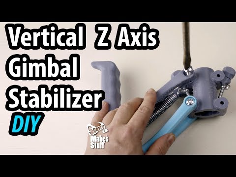 This steadicam, perhaps, is not quite an ordinary design. It is impossible to call it some outstanding invention, all this has already been invented before me. But some of its functions, namely a quick conversion into a small tripod and a few interesting "goodies" that I have not yet seen from anyone, are still present.
This fixture looks like this:
These photos clearly show its use as a tripod.
And this is what the steadicam looks like when folded:
The counterweights of this steadicam are located on its two front legs, they are ordinary M14 washers (standard size and enlarged (body)) which are selected depending on the required weight. The washers are fixed on the leg with an M14 nut, which is also a counterweight.
The next photo shows the hinge on which all this "hangs":
The design resembles a ball joint. The ball itself was bought at an auto parts store, it seems it is intended for attaching the gas stop of the trunk lid from some domestic car. The recess for the ball is simply printed in the handle, and from the usual ABS, which does not prevent this hinge from spinning very easily and isolating the camera from an ever-trembling hand.
Another feature of this steadicam:
There is a "trigger" in the handle, which is a brake. When you press it, the ball inside the ball joint is clamped, which helps to turn the camera more quickly, dampen its vibrations, and even tilt the camera up or down. In this case, the camera does not begin to shake along with the hand.
The balancing mechanism looks like this (bottom view):
Turning the plastic printed screw (by the handle at the bottom of the photo) you can move the platform where the camera is mounted along the longitudinal axis. If you loosen the screw located in the center of the photo, you can move the platform in the transverse axis, sliding it along the shaft.
To the right of the handle is an eccentric clamp, by loosening which you can turn the shaft along which the head moves in the transverse axis, which makes it possible to tilt the camera, for example, when using the device as a tripod. Or wiring overlooking the ceiling or the ground.
The legs are telescopic and fixed with eccentrics like on a real tripod
To unfold the product, to use it as a steadicam, just extend the front legs with weights by opening the eccentric clamps, move them apart, fix them with nuts and turn the head to the desired position.
To convert it into a tripod, just slide the third leg out of the handle.
It can be seen that when designing, I used SolidWorks. And while I was creating models for this little thing, I discovered a way to model with surfaces. It is always very interesting to learn something new about the ways of designing in CAD, and expand your abilities in this area. In general, the ability to create your own 3D models is important not only for a person who has a 3D printer. And how some people who have a 3D printer, but do not know how to create 3D models, have not yet got bored with this machine, I can’t imagine. After all, the ability in 3D graphics, and the presence of a printer at hand, gives great opportunities in creativity. Urgently learn 3D modeling if you don't already know how! I don't think this is bad advice. I myself have known him since school, then it was 3Ds max. A little later, when I was living with one aircraft modeling, I began to master Solidworks. A "stereo builder" appeared at me recently.
Okay, I got carried away with tediousness. I'll tell you how all this was printed and collected.
Printing and assembly
Everything was printed from cheap black ABS with 100% infill, some parts were printed from new PETG for myself (also cheap), namely the tips of the legs. The legs themselves are made up of aluminum shafts, from laser printer cartridges. These shafts are fairly light and strong aluminum tubes with diameters of 14, 12, 10 mm (it seems the most common sizes in A4 printers).
10 mm tube Fits easily and with little play inside the 12 mm tube, allowing the legs to be telescopic.
These tubes are called magnetic shafts, usually there is a long magnet inside, which can also be used, for example, to make a magnetic holder for small metal tools. There is also a photodrum - the same strong thin-walled tube, but with a diameter of about 24 mm. There are many applications for these tubes, and in every workshop for repairing and refilling cartridges there is a whole box of them, which in most cases is simply taken out to the trash.
By the way, before I cut all these tubes to the size I needed, I had to use them as drills.
Using a needle file, I drew teeth on one end of the tube, as on a core drill. The other end, where there is a narrow insert protruding from the tube, was clamped into a drill.
And with this “collective farm” drill, I went through all the holes where a shaft of a similar diameter is placed. By the way, this method can be used for deep drilling of soft materials such as foam. For example, laying cable channels in the wings of an aircraft model.
Yes, I know, it was possible to print the parts so as not to bore the holes, but at that time my printer printed quite terribly, and all because of homemade nylon bearings and oil-soaked PLA bearings. Therefore, the desire to pick up the gaps, something was not at all. Anyway, I was going to do post-processing and it seemed to me the best solution was to file everything to the right size. Now, of course, I won't do that. The printer has been completely redone, ordinary, but slightly modified bearings have been installed, all backlashes have been removed. And the axles move easily and, most importantly, quieter than with nylon, a paradox!
The screw that moves the head forward/backward was printed from two halves, which were then glued together.
Naturally, he did not enter his carving later. After a little thought, I found a solution how to grind one to the other. My cheap Chinese drill came with some strange abrasive blocks.
I still don't know why they are needed, can someone tell me? But I found my use for them, crumbling a little abrasive from them, using a bar with sandpaper, right into the thread, which needed to be “lapped”
Creepy photo. Not only is a terrible “collective farm” going on, but also a lot of dirt gets into the frame. I wanted to do this thing as quickly as possible in order to move on to other projects, which are in bulk in my head, so in the process of work there was no time to take care of the beauty of the photos.
"Nut" was also printed from two halves and this facilitated the lapping process. The screw, as it became clear, was clamped into a drill. (what would I do without it?) The halves of the nut were simply clamped with one left hand on the screw, and the screw was turned several times along the thread in both directions. The sand rubbed from these miracle bars quickly made the details compatible.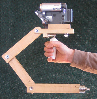
The screw that goes into the camera has been pulled out of a small pocket-size camera stand.
The large wheel that protrudes from the sides of the head to allow the screw to be driven in was printed and simply glued to the wheel of the tripod screw using an adhesive made from acetone and abs.
The most difficult thing for me was to figure out how to make leg restraints so that when unfolding they do not fall out on the floor. What I came up with, I myself do not really like and seems too complicated, but another has not yet come to mind.
This is what these restraints look like - wire hooks that hang inside the legs. The plastic sleeve is glued into the lower leg extender:
And the hook clings to the rod inserted into the plastic hinge that secures the upper leg to the steadicam body.
Or as in the case of the 3rd leg: a rod inserted into the handle.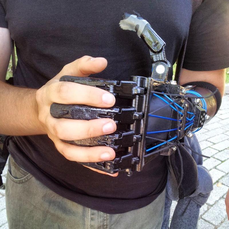
These rods, like the axles of the eccentric clamps, are made from old bicycle spokes
There are recesses for the eccentric in the upper parts of the legs:
The whole clamp consists of 3 parts: body, eccentric and shaft.
Cam body is simply glued to the leg with epoxy, like all other places where metal and plastic are fixed.
The hinge on which this whole structure wobbles, as I said, was purchased from an auto parts store.
The surface finish of the ball itself was appalling. As if it was sharpened by hand, on a loose lathe. Unfortunately I didn't take a "before" photo. But bringing the ball to an almost mirror state did not take much time.
Again, a drill, sandpaper (grain size 120, 400, 800, 2000), a drill with a felt nozzle, and GOI paste came to the rescue.
Ah drill! What a useful invention. This is a lathe, and drilling, and grinding, and lapping machine in one case.
The final polishing of the surface was carried out simultaneously with a drill and a drill with a felt nozzle lubricated with GOI paste.
I think the design of the hinge will be clear from this render.
The trigger simply presses on the ball and locks it in its seat.
A few words about fasteners.
Most fasteners are bolts and nuts inserted into printed slots. But there are also a handful of small screws, most of which are in the head
Post-processing.
There is nothing supernatural in post-processing. First, sandpaper 80, then 120, then 400 and finally 800. After that, the surface was pre-smoothed with a soft watercolor brush dipped in acetone. And the final touch is processing in an acetone bath without heating, but with a fan inside, for 15 minutes, which removes the white coating from the plastic remaining after brushing, and gives the final gloss. On solid fillings, after all manipulations with solvents, a pattern of this very filling appears. Therefore, it would be better to use the method proposed by MexaLbl4 in this article. I myself tried this method after making the steadicam, successfully replacing the aluminum powder with easily accessible baby powder, and was very pleased with the result. Thanks to MexaLbl4 for the idea.
Conclusion
I think it's time to end the story and start summing up. In principle, the product turned out to be working, so far I managed to try it only with a mobile phone as a camera. Stabilization is the video turns out to be smooth, but sways a little, until I realized this problem is from incorrect settings or from an unsuccessful design. An attempt to put on a weighty "reflex camera" revealed another drawback. The lateral balance adjustment clamp rotates under the weight of the camera, if you pull it up and down, no matter how you tighten it.
.jpg?x-oss-process=image/resize,p_100/format,webp)