3D print beds
LayerLock 3D Printer Build Surfaces
- Home
- Store
- 3D Printer Accessories
- Build Surfaces
- LayerLock Build Surfaces
LayerLock provides a variety of build surfaces and build plates designed for stronger bed adhesion for both advanced and standard materials. With LayerLock Garolite Build Surfaces, successfully printing warp-free parts out of NylonX, NylonG, and other nylon filaments will be a breeze. This type of surface also successfully prints standard filaments such as PLA, PETG, TPU and more for a plethora of material compatibility. With LayerLock Powder Coated PEI Build Plates, users have a reliable alternative bed surface for successfully printing standard filaments such as PLA, ABS, PETG and flexibles. Both types of bed surfaces are durable, dependable, and require little to no maintenance so strong bed adhesion is attainable without the huge hassle. Take your 3D printing to the next level with these advanced build surfaces that will help you successfully achieve warp-free projects for a lifetime.
LayerLock Build Surfaces Collections
All LayerLock Build Surfaces 3D Printer Build Surfaces
Technical Specifications
- Material Surfaces Available: Garolite, PEI, Surface for Polypropylene, Surface for SLA
- Available in various sizes—check individual products for guaranteed printer compatibility
- Material compatibility for Garolite: NylonX, NylonG, Nylon, PLA, PETG, TPU, and more
- Material compatibility for PEI: PLA, ABS, PETG, and flexibles such as TPU and TPE
- Material compatibility for Surface for Polypropylene: Polypropylene and OBC
- Material compatibility for Surface for SLA: Most LCD / MSLA, Laser, and DLP resins
LayerLock Build Surfaces
LayerLock Garolite Build Surfaces
Superior bed adhesion to Nylon based materials like NylonG
LayerLock Build Surfaces for Polypropylene
Get the best first layer with polypropylene and OBC filament
LayerLock Powder Coated PEI Build Plates
Great first layers and easy part removal with this flexible build plate
LayerLock SLA Resin 3D Printing Build Surface
Achieve strong bed adhesion in SLA printing with this surface
LayerLock MagBase
Easily add a magnetic base to your 3D printer for interchangeable surfaces
Guides & Articles
How to Succeed with Quantum Dichromatic PLA Filament
Follow this guide for tips and tricks on how to get the best results when 3D printing with Quantum Dichromatic PLA filament.
How To Succeed with LayerLock SLA Build Surfaces
Successfully achieve strong bed adhesion for Laser, DLP, and SLA resin prints using LayerLock SLA Resin 3D Printing Build Surfaces.
How To Build A Successful Makerspace
Find out the necessary components to create an effective space for your maker community.
How to Succeed When 3D Printing with Polypropylene
Successfully produce 3D printed parts out of polypropylene filament with these tips on achieving stronger bed adhesion and minimizing shrinkage.
Tech Breakdown and How to Succeed: Ionic Hybrid Support Material
Supporting engineering-grade filament has been difficult without a support material dedicated to higher temperature 3D printing. Ionic aims to solve that.
How To Succeed with OBC 3D Printing Filament
From Dow Chemical, OBC combines flexible and rigid into one unique material with properties of both.
How To Succeed with LayerLock Garolite Build Surfaces
Successfully achieve strong bed adhesion for NylonX, NylonG, and standard filaments using LayerLock Garolite Build Surfaces.
How to Succeed with LayerLock Powder Coated PEI Build Plates
Powder coated PEI steel sheets are a great alternative build surface for strong bed adhesion. Here's how you can succeed using this durable build plate.
How To Succeed When 3D Printing With Nylon
Learn how to 3D print Nylon like a pro. Nylon is a stronger and more durable alternative to PLA or ABS and easy to 3D print with using these Tips and Tricks.
How To Succeed When 3D Printing With ASA Filament
Follow this step-by-step guide to learn how to print with ASA, the perfect material for any outdoor projects.
About LayerLock Build Surfaces
LayerLock 3D Printer Build Surfaces strengthen the bond between the print bed and both advanced and standard materials. LayerLock Garolite Build Surfaces are made out of linen-based phenolic sheets, allowing for just enough texture on the surface to provide a sturdy grip for prints to hold onto while still having a fairly smooth finishing surface. Alternatively, LayerLock Powder Coated PEI Build Plates have PEI powder coated onto a flexible spring steel sheet which leaves behind a bumpy surface on the plate and produces a charming, rugged finishing texture on the bottom of prints. Both types of bed surfaces are engineered for easy installation and to withstand thousands of print jobs. Successfully achieve warp-free prints with zero hassle using LayerLock 3D Printer Build Surfaces.
WHAT'S THE BEST 3D PRINTER BED SURFACE?
If you asked us 3 years ago what 3D printer plate would we recommend, we would say without a doubt the glass bed. Now, we are not so sure anymore. The progress in the development of 3D printers is truly astonishing. You can choose from PC spring steel sheet to PEI plate, carborundum glass, or the good old flexible magnetic build plate. So which one represents the best 3D printer bed surface?
This article will present our results of different tests and a comparison of 3D printer bed options. The printer plate presents a very important part of a 3D printer. It can help you get the best 3D results or make your 3D model impossible to remove. A lot of makers also struggle with the first layer- to some, it is impossible to stick the filament to the build plate. One of the most challenging problems 3D makers have is when a 3D print warped.
3D print warping can happen when the 3D filament layers on the 3D printer plate cool down too quickly and consequently shrink. This reaction causes the filament to contract and pull away from the printer bed, resulting in warping/curling.
Everybody loves PLA filaments because are one of the easiest to print. They are especially popular because of the opinion that you don't have to heat the bed of the printer to get good results.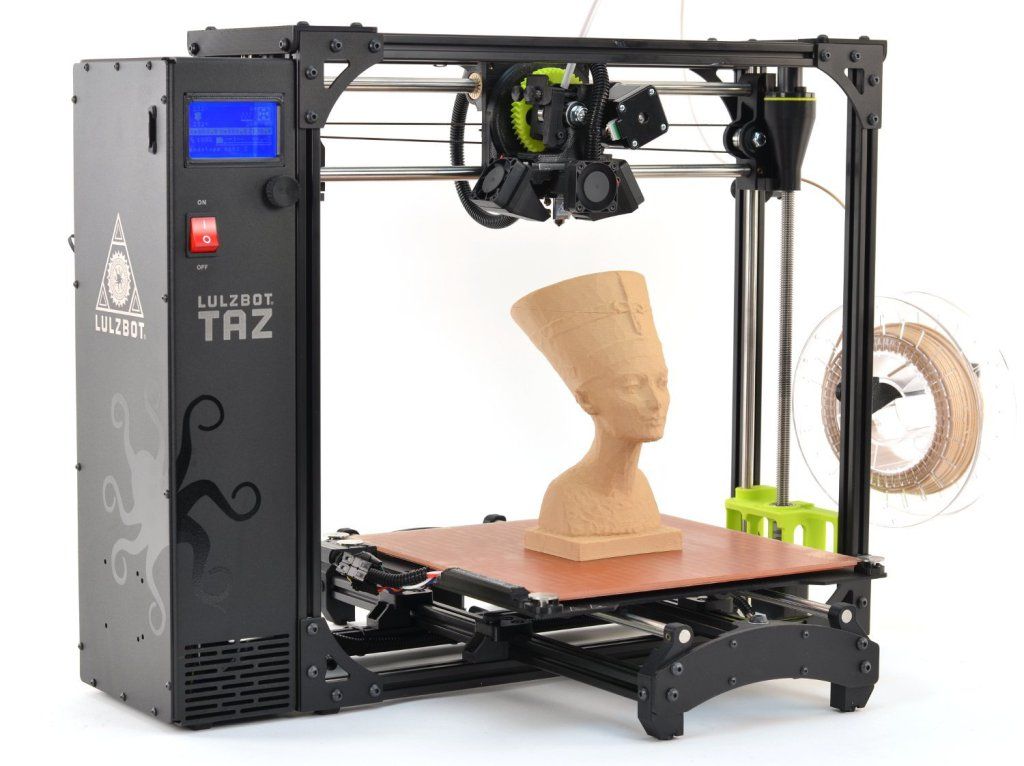 Here we don't agree completely. For getting the best results you have to avoid warping. How do you avoid 3D print warping? Well by using a heated build plate. The heated printer plate keeps the filament at a temperature just below the point before it would solidify (the glass transition temperature), ensuring it stays flat and connected to it.
Now you see why a 3D printer bed is very important and can easily make your life complicated or affect your final result. This is why we decided to analyze and compare the most used 3D printer.
MAGNETIC BUILT PLATE
The magnetic plates were one of the most popular 3d printer beds. With the 3d printer magnetic build surface, you didn't need any clippers or additional accessories to make a great 3d print. Thanks to the magnets, the magnetic beds stick to the frame through magnetic force. Magnetic build plates have great adhesion, especially with PLA and SILK but we still recommend the use of Dimafix spray or 3dlac.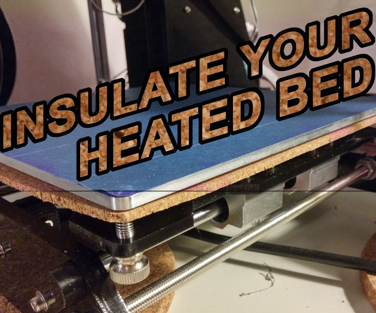 These sprays help the first layers to stick firmly to the bed and when the 3D model cools down it is easier to remove it. You will probably need a spatula or just bend the plate and sometimes the model will detach.
Some makers have warned us that 3d model removal can damage the surface though, so be careful and gentle when popping off a print or banding the plate. Being too aggressive with print removal can cause the bed to get damaged.
One of the cons is its durability; the heat can degrade the magnetism of the platform. Also, the use of a spatula or any type of removal will damage the bed. Almost every use will leave a mark on the surface.
This magnetic platform can be easily cleaned with alcohol or acetone. Regarding the temperatures, this printer bed can heat up to 80 °C, while others can go up to as high as 150 °C.
CARBORUNDUM GLASS BED
When comparing the magnetic platform with the glass bed, we would recommend the glass platform because of its durability, and the stiff, dense, and cheap material. Carborundum Glass is smooth and flat and if the glass is thick around 3-4 mm you can easily heat it up to 150-400 degrees. It has a nano-molecular coating that appears super viscous after heating. We recommend the use of Dimafix or 3dlac so it will be easier to remove the 3d model. Because of its strength and firmness, the life span is longer compared to a magnetic platform. Besides the spray, you would need to use the bed clips and a spatula when removing the 3D model.
Pros:
- Low cost
- Long life span
- Compatible with almost all filaments
- Produces smooth bottom finish on prints
- It takes only 3 minutes for hotbed to cool
Cons:
- difficult removing bigger 3D models
- you need to use a spatula for removing 3d prints and can hurt yourself/cut on the edge of the spatula
REMOVABLE PC SPRING STEEL PRINT SHEET
The PC magnetic build plate is a lot stronger and more resistant than the old magnetic plate we get with Ender 3 PRO.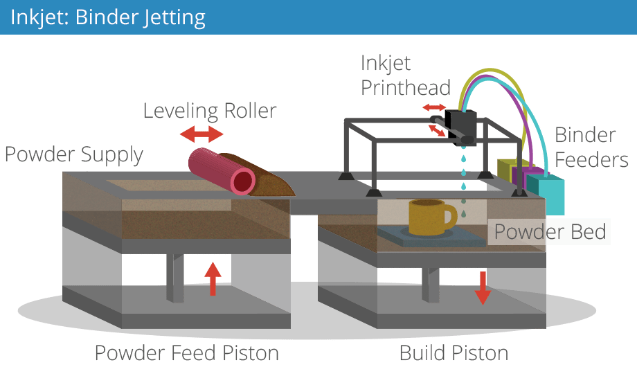 This one resists higher temperatures and is more flexible, it is also removable and can stick to magnetics very well. It matches great with PLA, PETG, ABS, ASA, TPU, and other filaments. With this plate, you won't need any tape, spray, or shovel. It's easy to adhere to the printing surface, and it's easy to remove the prints, just flex slightly to pop your print right off.
PC is an excellent upgrade because it can withstand the numerous heat cycles that a 3D print bed goes through from print to print. Its life span is also longer than the old magnetic plate because you won't need any accessories to take off the 3d print, so you won't damage the plate.. You just pop and the model removes itself from the surface. You can get the PC spring sheet if you buy Ender 3 S1, Ender 3 V2 NEO, and Ender 3 S1 Plus.
PEI MAGNETIC BUILD PLATE
PEI stands for Polyetherimide, a surface that can be used for all types of filament on a heated or unheated print bed.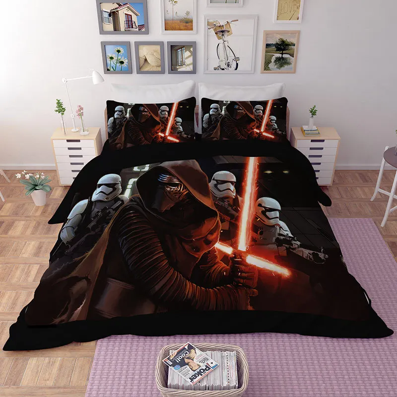 This platform doesn't need any additional clips, sprays, or spatulas. The removal of the 3d print has never been easier! There is also no need for surface preparation, so is the most convenient 3d printer platform to use.
PEI printing plate has excellent mechanical properties such as radiation resistance, high and low-temperature resistance, high-temperature stability, high wear resistance, good flame retardancy, chemical resistance, and electrical insulation characteristics.
The newest Creality printers such as CR-10 Smart Pro and Ender 3 S1 PRO have already the PEI plate
PROS
- excellent adhesion of the 3d model and an easy removal
- a smooth surface finish on the 3d model (while it remains undamaged)
- good thermal conductivity for a heated bed
- gold frosted surface (flame retardant and heat resistance)
CONS
- It’s relatively soft and can be damaged by a poorly adjusted print bed or excessive scraping.

- it cost more than the other 3d printer beds
Comparing the PEI and the classic magnetic sheet, we see the difference not only in the surface of the sheet but also in how the sheets are assembled; the magnetic plate has magnets on both sides, and the PEI sheet is made of 2 pieces; first you need to fix the sticky part on the aluminum bed and then put the PEI magnetic sheet on it and take of the protection foil.
CONCLUSION
When comparing different 3D printer beds it is important to use the same filament, for example, you can not compare the adhesion of PLA filament on a magnetic plate with the adhesion of PETG on carborundum glass.
Testing different 3D printer platforms using PLA and PETG we found out that the weakest adhesion has the removable magnetic plate which is not shocking since it is the oldest among all the printing plates and the most outdated. The carborundum glass has definitely better adhesion and also a longer life span. The glass is a great choice for beginners because is less sensitive to human errors like crashing the nozzle into the 3D print surface during the bed leveling. Crashing the nozzle in the magnetic sheets can leave permanent damage signs.
It is also very important to mention that the removal of 3d models from glass can be a little bit dangerous. You will need a spatula to take the model off and the edge of the spatula is very sharp, so you need to be careful you don't cut or injure yourself.
If we compare all the platforms the winner is definitely the PEI plate sheet. Its special gold frosted coat works like magic. It has great adhesion and the removal of 3d printed models has never been easier. Removing the bigger models is much easier to do it on a flexible bed than on any type of glass. A great printer platform is also the PC spring steel sheet, since it works similar to the PEI plate except it doesn't have the goledn coat, but if you bend it the 3d model will ''pop'' the same way 😊
Another thing important to mention is that you should never remove the 3D print while is not 100% cooled down, no matter what bed you have.
Printer setup, slicers, model preparation
Part 2 of 'Introduction to 3D Printing' article, previous one can be found here:
Introduction to 3D Printing, Part 1
3. Moving on to practice
3.1. Unpacking and initial setup
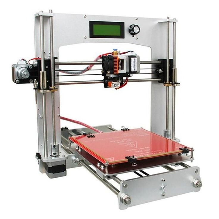
The parcel arrived about a month later, we pick it up, unpack it.
The box contains the printer itself with extruders with 0.4 mm nozzles removed for transportation, two spools of plastic, a small package with spare bolts, nuts and wrenches for working with them, as well as a 4 GB flash drive with test objects. The heated platform has kapton tape and a sticker in English-Chinese, explaining that it is not necessary to remove it.
After assembly, my first thought would be to start printing from the included flash drive, but I found its connector only late in the evening, because printing was done through a computer.
First of all I tried to calibrate the heating table (often called a heated bed, there is no fully established translation here - even I allow the use of both options in the article) using adjusting screws, but more on that below. Then I connected it to the computer and began to deal with the software.
3.2. First print
The basic “regular” printing program is Repetier Host, by today’s standards, a shaggy version, which sees the printer without additional tambourines and allows you to press the “Print” button on a test model downloaded from the Internet without hesitation, which is an elementary cube 2x2x1 cm.
When you press Print, the program thinks about something for a short time, “flashing indicators”, after which the printer comes to life and ... warming up begins. It turns out that you can't just send something to print. Not only, as you know, printing itself is very slow, but before each print, you have to wait about 7-10 minutes until the heated bed reaches a temperature of 107 degrees. At this time, the printer only buzzes with fans, without producing useful work. When heated, the extruders themselves also warm up, but they take much less time - the slowest camel is the bed.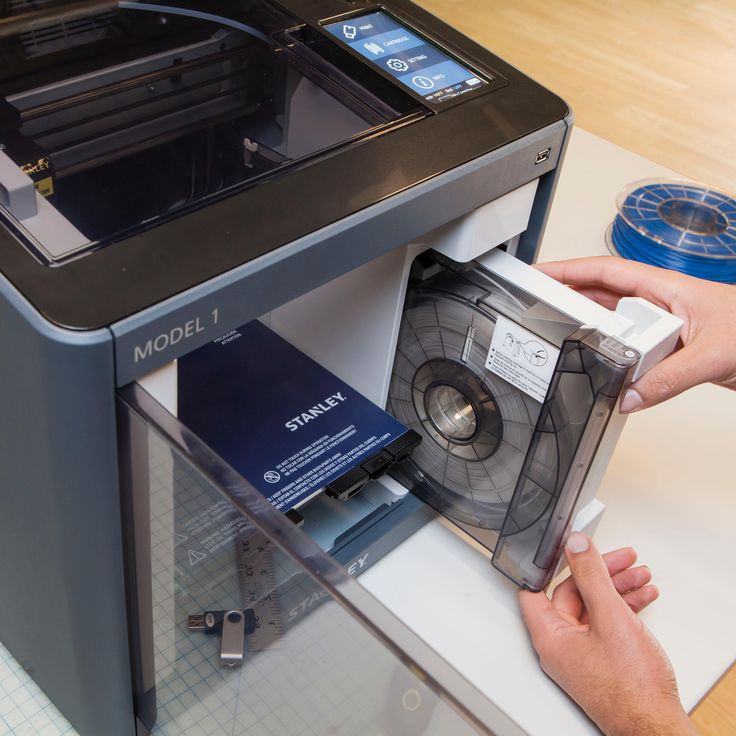
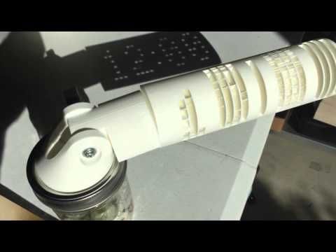
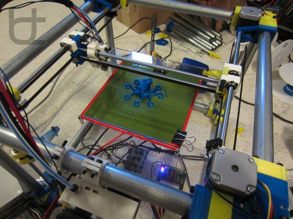
The printing process has finally begun. First, the printer draws a lattice called a raft on the “bed”, and only after that it gradually prints the original 2x2x1 cm cube on it. The printer plays a melody about the completion of printing, takes the carriage to its initial position, continuing to buzz with cooling PSU and motor fans.
At this point, I will again "fall" from the description of the process of mastering the printer directly back into theory.
A raft is usually a double sparse lattice of plastic threads, which is lined up on a substrate before printing on the model itself. It allows you to partially compensate for temperature loads and the unevenness of the "table", but it greatly spoils the lower part of the model: instead of a flat and smooth bottom surface, you get a set of poorly glued plastic threads.
By the way, the same cube:
The heated bed itself is installed using several (usually four) spring-loaded adjustment screws that allow you to calibrate its level - so that all four of its corners have the same gap between the fully lowered extruder and the very surface of the bed. But no matter how you twist and calibrate them, the heating surface itself is often curved, so at best you'll adjust the corners, the center will almost certainly be concave, or rather concave. I can't guarantee that this is a general trend and not my particular case, but most likely the platform will only be relatively flat, and the center point, located at the maximum distance from the adjusting screws, will also be the most out of the common surface.
This will either cause the extruder to scrape across the table in the center, or if you adjust the center, there will be too much clearance towards the edges, and therefore the contact between the plastic and the table will be mediocre, resulting in delamination (peeling off) edges of the model. Therefore, for alignment, glass is often placed on top of the heating table. This further increases the warm-up time, but reduces printing problems associated with uneven print surfaces. I will say that it is better to calibrate the platform when it is fully warmed up.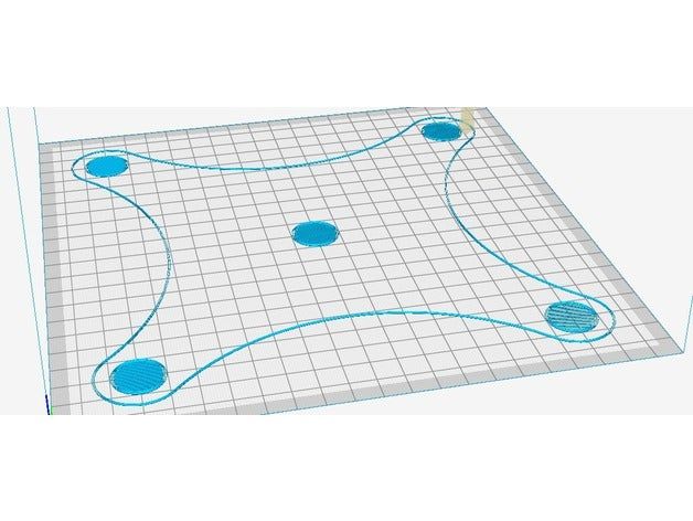 at the same time, the gaps will correspond to the real printed ones ... yes, by short twisting the screws with an attempt not to burn your fingers at the same time))
There was also a review where it was recommended to heat the platform longer before printing in order to increase the uniformity of its heating and thus reduce its bending, but I did not personally check the effect of this.
3.3. Slicers
If you are even a little interested in 3D printing, then you know that a slicer is a program for turning a three-dimensional model into a set of commands that the printer understands, called g-code.
Translating a model into an LCD so that the print result is digestible even with the intricate shape of the model is a separate software art in which slicer manufacturers compete. Here I can’t help but recall the famous photograph of Bill Gates, which well describes the generation of this same w-code by the slicer))
Next, I will give a brief description of several popular slicers, so that it is clear what they are, why and in the direction of which names to dig the Internet if necessary.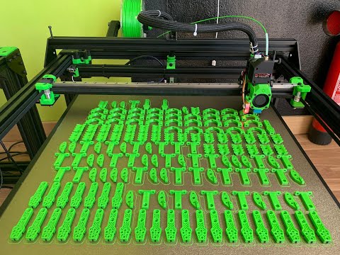 This photo was taken from one of the slicer tests on the internet, and is only shown to illustrate that the LCD generated by different slicers can lead to significantly different results when printed. I do not recommend focusing on this picture according to the principle “this slicer obviously did better”, because this will be highly dependent on specific 3D models and slicer versions.
The printing program that came with the printer - Repetier Host, worked for me on a regular basis with only one Skeinforge slicer that came with it.
So, the main slicers:
1) Slic3r . Perhaps the most popular of today. Constantly being improved. Newer versions are often less stable than previous versions, so despite having 1.2.9 Stable at the time of writing, the older 1.1.7 is often used , also marked stable. I note that in the new version a lot of changes have been made in terms of the interface, for example, a normally made visualization of the model slicing has appeared.
2) Cura . Also a very popular slicer. It is a complete all-in-one printing system. Convenient "user-friendly" interface, which began to strive for in later versions of Slic3r . I can only say that my communication with this slicer ended with the fact that I could not connect my printer to it without a tambourine, therefore I only used the code generated in it a couple of times. This is not a flaw of the slicer, but only my experience with it.
3) Kisslicer . Even shorter: relatively popular, but I did not work with him at all, therefore I cannot give a description.
4) Skeinforge . About it, you can limit yourself to the fact that its support was discontinued a few years ago, so I do not recommend using it except for the case “it comes with the kit, you need to print it now without setting anything up”. I mentioned it here only because it was the first slicer that worked without problems with my printer.
I agree, the description of the slicers is a little strange and too vague.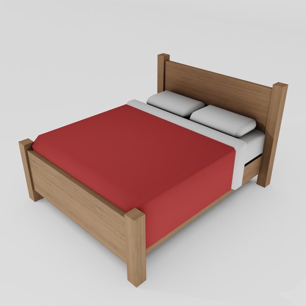 I proceeded from the principle of reasonable sufficiency: if a given slicer performs its work no worse than another according to the results of several tests, then I take the one that is more convenient for me and work with it until the information appears that “this one is clearly better” . This will not give the best result, but it will allow you to devote reasonable time to the technical aspects of printing, without moving, as I said above about homemade printers, into an excessive cycle of self-production. As a result, I settled on Slic3r and use it to this day. This article does not aim to accurately describe and compare the work of all slicers, so I will leave the selection of a slicer for your individual goals and objectives.
The slicer itself is put into operation either at the moment the object is sent for printing, or, as they often do now, slicing is carried out right in real time immediately after loading the model. In fact, on modern computers, the time for a slicer to convert a model into a f-code is short enough not to mention it separately with a phrase like “after two hours of slicing, the model was still ready for printing.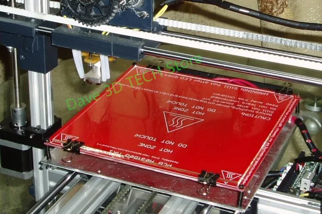 ”
”
Also, I do not give here any specific settings for specific slicers, but below in one of the chapters I will give a few common ones for all of them.
3.4. Preparing the Model
After I had already made some printouts of test cubes and various pyramids and polygons with round holes, I wanted to print something specific. I took a model of a smelting furnace with a slag spill conveyor that I once made and, without much thought, sent it to print.
At this point, seasoned 3D printers burst into Homeric laughter, because. the whole lamerism of trying to print such a model without the slightest preparation on the face, but, as I said above, this model was sent for printing only out of interest and after a couple of hours of getting to know the printer.
Although I turned on the automatic generation of supports, after two hours it became clear that there would be nothing worthwhile in the output. Parts of the conveyor are too thin for printing at this scale, some of which are generally hanging in the air, which, due to their thinness, cannot be saved by any generated calipers.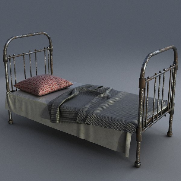 As a result, I got a bunch of tangled threads, in which in some places the outlines of the conveyor racks and the frame of the boot block were guessed. So I got acquainted with the need to prepare the model for printing.
And again an excursion into the theory. As I already wrote in the article about the layout of the church, I divided all 3D printing for myself into two ideological approaches: engineering and design. The first relates to working with printing gears, fasteners and spare parts for a new printer, RC models or some other mechanical structures, while the second is responsible for printing the statue of Zeus, brick walls with windows and all sorts of scale models of something (for example, any statue - This is also a scale model.
This division is rather conditional, but at the same time real. Gears and mechanical assemblies are easiest to do in the software designed for this, the same SolidWorks , Compass 3D and others. At the same time, you make your entire model with holes, chamfers and elements of bodies of revolution, after which you export everything to a stl file, open it in a slicer, and then it will convert the model into an LCD without requiring additional intervention from you.
At the same time, an attempt to make in the drawing program a spaceship, a statue of Buddha, or the same brick wall of a building in which each individual brick stands out from this wall will end up in a quite predictable time for developing such a model to infinity, which is equivalent to the effective impossibility of creating such models. And in general, do you represent a drawing of a Buddha statue in solid? Here I am, no)) There are completely different programs for such things - for example, ZBrush or MudBox for sculptures or the same great and terrible 3DSMax for everything else.
Engineering programs are initially designed to work with curved surfaces, chamfers and other elements of three-dimensional design and are usually able to produce a printable result on the mountain - a mesh (this is the name of an object consisting of triangles) with good topology, but the same 3dmax when you make, for example, a brick wall, when you try to combine it into a single non-intersecting mesh using the Boolean -> Union operation, you are guaranteed to get an unusable result.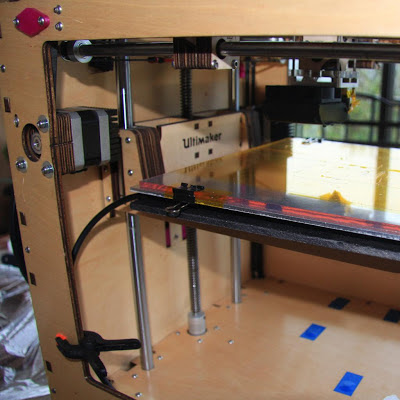 More precisely, most likely you will get a void instead of an object. And I'm still considering the simplest case, sometimes topology errors are not visible to the naked eye, but the model will be unusable for printing. The bottom line is that 3dmax, despite the fact that this is a program for working with three-dimensional space, is not suitable for working with volumes. Being originally sharpened to work with triangles hanging in the air, it remains fundamentally so to this day.
Before we say what model preparation is, we must first pay attention to the file format used today for printing STL . This format contains a model by writing it in separate triangles, when, for example, a cylinder is divided into many “faceted” segments, which ultimately reduce to these same triangles. Those. there are no curved surfaces, spheres and tori, like spoons from the Matrix, all objects are approximated into figures consisting of a bunch of triangles. Couldn't resist a little easter egg in the picture.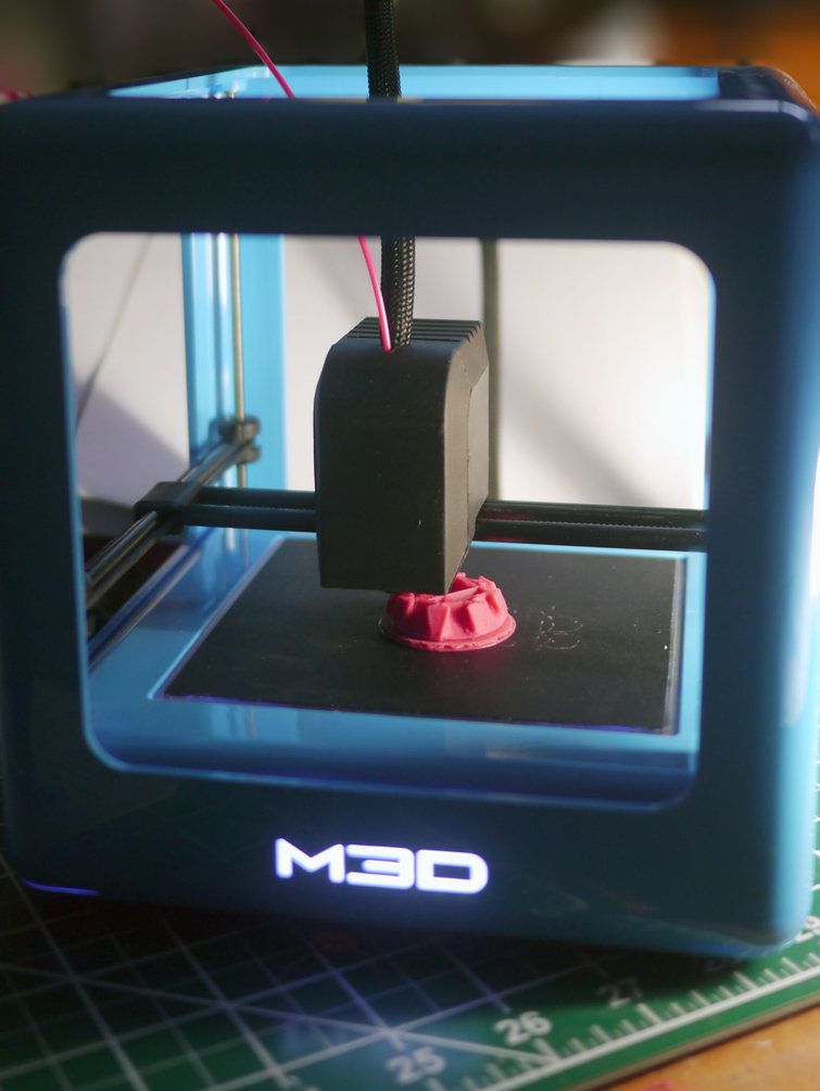
The slicer reads triangles from the stl file, cuts this set into thin layers, which as a result turn into the paths of the print carriage. As long as you are dealing with a correct mesh, there are no problems, but as soon as a hole appears in it or the intersection of triangles, the slicer may start to “stutter”. And this is not always exactly a “mistake”, it’s just that the slicer must know exactly how to interpret your model. And if one of the edges of your box is missing, does this mean that it simply should not have one wall and it should be completely hollow and thin-walled, or should this hole be closed automatically and the box be considered whole. This is the simplest example, and there are a lot of situations with a completely incorrect grid, when it cannot be printed correctly at all.
Now let's talk about the preparation of the model itself. If above there was a long boring theory about the topology of the model and its export to stl format, the practice itself in the description is much simpler: only the preparation work itself is long in it.
1) The item is relevant for design programs (read 3dmax). The model must have the most correct mesh possible during the initial export. That is, if you make a model for printing in the same max, make sure that, if possible, it does not have open edges (holes in the grid), triangles intersecting in one element and similar indecencies. The model recovery system will most likely fix this, but it's best to keep the risk to a minimum.
2) Relevant for everyone. Complex or large models need to be divided into elements, because. it is either impossible to print in one go, or the result will be noticeably lower quality than printed correctly in several parts, and then glued together.
3) Correct position of the model. The lower the height, the faster the model prints - the total print speed in height is always lower than the print speed of the layers themselves ... I understand that the wording is not very good, but you can understand))
4) Specific practical advice buried in a pile of theory)) Drive the model through model recovery system.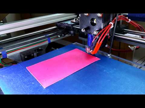 Firm Netfabb is one of the developers of such systems. Company Microsoft bought this technology and made a free service for restoring models in the cloud. For design printing, this is a must have. Register an account if you don't have one, and run the model through the service at https://netfabb.azurewebsites.net/
Run through the restore service is primarily needed for models exported from max, made in the style of "a bunch of intersecting boxes", for programs exported from CAD, this is necessary only sometimes, when the program during export could not make the correct topology. However, this often happens.
After processing on this or similar service, the model is ready to be sent to the slicer and printed.
3.5. Some Features of Model Making
I'm going to be a bit inconsistent here and go back to the stage when you're still painting or about to remake your model for printing.
I noticed for design printing. Such printing is usually associated with printing the product in some scale, but when no one will sit with a caliper, measuring out the exact size.
The simplest one: you want to print railings for the roof of a building. In real life, they have a thickness of about 4-5 cm, but with a print scale of 1/80, you will get their diameter of about 0.5-0.63 mm. Given the nozzle of the printer (in my case 0.4 mm), they will be either 0.4 or 0.8 mm if we print in two perimeters. I will say that print them with a thickness of 1 perimeter, i.e. 0.4 mm would be completely unreasonable - for ordinary ABS plastic, such a thickness is too “openwork”, plus it will be very difficult to glue them on the building.
The same goes for any object that needs to be solid or at least solid after printing. My attempt to print the conveyor racks shown a few pages above, which are only a millimeter or less thick on scale, and the conveyor belt itself, which is about a centimeter thick in real scale and about a quarter of a millimeter thick in print scale, is a good example of this. The scale of objects must be realistic for printing.
A couple of points related to engineering printing. When you print a cylinder with a diameter of 10 mm and a hole for it 10 mm, then, of course, the cylinder will not enter this hole, because. no tolerances for the correct fit of this cylinder will be observed. There are several reasons:
1) Inaccurate operation of the mechanics of the printer, due to which each subsequent layer can be stacked with a slight arbitrary offset. As a result, this reduces both the diameter of the bore and increases the diameter of the cylinder itself.
2) Thermal expansion on heating and therefore shrinkage on cooling. The shrinkage of ABS plastic is 0.5% on average. It is desirable to take this into account when translating the model into a printed STL file. Most slicers are able to scale the model to the desired size. I don’t have enough information about how the holes shrink, when printing, I focus only on linear dimensions. PLA plastic does not have a noticeable shrinkage effect.
3) The accuracy of holes and small diameters also strongly depends on the printing speed - the higher the speed, the higher the error will be.
4) The actual width of the laid thread compared to the theoretical one may vary due to the slightly floating diameter of the rod and the not quite accurate diameter of the nozzle itself.
In my experience, the difference in diameter between the hole and the element inserted into it should be in the region of 0.3-0.5 mm in diameter.
Scientists have developed elements of self-assembly furniture using a 3D printer / Sudo Null IT News0001
Israeli scientists have introduced the next generation of flat-pack technology with self-assembly furniture. According to them, 3D-printed wooden parts can be adapted for self-assembly into complex shapes, such as beds and wardrobes.
Usually furniture parts are made by sawing, carving or pressing. However, scientists at the Hebrew University in Jerusalem took a different path. They used a process where the wood changes shape and texture as it dries.
A few years ago, researchers came up with an eco-friendly water-based ink made from microparticles of wood waste. "Wood flour" is mixed with cellulose nanocrystals and xyloglucan, which are vegetable binders. Scientists have started using ink in a 3D printer.
They recently discovered that how the ink is applied dictates how the product behaves as moisture evaporates. For example, a flat disc printed as a series of concentric circles dries and shrinks to form a saddle-shaped structure reminiscent of Pringles potato chips. The disc, printed as a series of rays emanating from a central point, turns into a domed or cone-shaped structure. The final shape can also be controlled by adjusting the print speed.
Shrinkage occurs perpendicular to the wood fibers in the ink, and the print speed changes the degree of their alignment. A slower speed leaves the particles more randomly oriented, so shrinkage occurs in all directions. Faster printing evens them out and the shrinkage becomes more directional.
Scientists have learned to program the speed of printing and its trajectory to obtain various final forms. So, if you add two rectangles printed in different orientations, after drying, you get a spiral.
Researchers have also shown that they can program the print path, speed, and stacking to control a particular direction of shape change, such as spiraling a rectangle clockwise or counterclockwise.
Further refinement will allow the team to combine seats, domes, spirals and other design items to create objects with complex final shapes, such as a chair.
Ultimately, scientists believe, it will be possible to produce wood products that will be delivered to the end user in a flat form, and then "self-assemble" in the process of drying.
They also believe the technology could be licensed for home use so that consumers can design and print their own wooden objects using a conventional 3D printer.
Researchers are also exploring whether the morphing process can be made reversible to change the shape of the resulting object.
In early 2022, IKEA launched the first collection of 3D printed Flamträd products.