3D printed pressure tank
3D printed compressed air tank
June 3rd edit:
To readers redirected from hackaday.com
There has been a mash-up of informations on the article you came from. For the sake of better understanding, let us provide you with some context and discuss a few details.
We are experimenters building robots in a club, we do not build commercial air tanks. We take part in the Eurobot contest every year, and one action to be performed this year could be nicely executed with the help of pneumatics and compressed air stored in a tank placed in one of our robots. Our requirement was to have as big as a tank to fit in a prismatic rectangular space. A cylinder would not have done the job properly and would not have been innovative. A 3D-printed air tank would do both, so we tried a few ideas.
Then, to address criticism emitted in the comment section, 4.0 bar = 58 psi and 6.5 bar = 94 psi, these are low pressures. 6.5 bar was the pressure we subjected our prototypes to, whereas 4. 0 bar was the maximum pressure the tank would have to endure during contest use, our security factor there is at the very least 1.6 on the prototype used in our robot, which would most certainly not be tolerated on a commercial product, but enough for our specific application. Then, the tank is enclosed in our robot behind 2 mm thick (0.078 in) aluminium panels. Shrapnel would not be able to escape the robot and cause injuries any rupture had occurred.
Finally, we use PLA filament to 3D-print our parts, not PVC as some readers understood. We do not understand why our blog post somehow ended up being embedded in a post on hackaday.com relating events regarding the safety of PVC pipes use for compressed air.
In order to perform the funny action for Eurobot 2016, we considered a pneumatic umbrella and needed to have a reservoir of compressed air in our robot.
The tank would need to sustain prolonged operation at 4 bar and the pneumatic system as a whole would have to be airtight enough so that a funny action triggered 60 minutes after refilling the tank would still be successful.
3D printing allows for fast prototyping at low costs and super low iteration cycle times. Once you get used to printing parts and you have to test a new idea, you just end up doing it without a second thought. At CVRA we 3D print main mechanical internal parts as well as cosmetic external bodyshells. We can make stiff parts as well as bendable ones. Pretty much every idea we have is a candidate for 3D printing at some point.
So… I hear you have to use a compressed air tank for your pneumatic system, right? What if you just… 3D print it?
After all 4 bar is not such a high pressure. We are routinely using PLA filament and this material has a rather high yield tensile strength. Doing a quick “back of the envelope” calculation indicates wall thickness can be pretty low.
Our first attempt was a 40x40x40mm air tank exported in STL as a solid and printed with a wall thickness of 4 layers and 20% infill. A 3mm hole was drilled on the side, and deep drilling the tank opened a clear venting channel within the infill structure. The test was a direct success. The tank was able to sustain pressures up to 6.5 bar without a hitch and be airtight enough to successfully deploy the pneumatic umbrella after a 1-hour delay.
The blue cube is the tank.
Then came the time for a larger tank version our robot would accommodate, ramping up in volume from 40x40x40mm to 65x40x80mm, a roughly +225% increase, leaving infill aside, opting for a 6-layer wall thickness and having an internal support helping with the leveling of the innermost layer of the top wall during 3D printing.
The tank exploded into pieces just centimeters to my face when subjected to 5.5 bar pressure.</p> I was wearing thick clothing and took the precaution to hide my face behind my arm, so nothing happened to me. But this is a clear reminder things can go wrong with only 4 bar of pressure. (Actually 2 bar are more than enough to do nasty damage. As an experiment we made a pointy steel javelin whose ejection velocity from a 6mm diameter pneumatic cylinder was really nasty enough any interference with human flesh had occurred.) </p>
- Rule #1: wear protective glasses when subjected to even remotely possible projections.
- Rule #2: hide behind a protection wall when things can potentially explode.
This is a cross-section view of the faulty design. The internal structure is not bound to the walls.
It is supposed the pressure inside the tank inflated the walls enough to accentuate stress concentration at the inner corners and to cause one of them to yield. The rest was a chain reaction resulting in a handful of fragments flying across the shop.</p>
External features remain the same as for prototype #2 since the function and bulk volume have to be maintained. Changes are found inside. End-filleted ribs fill the inside of the tank, effectively preventing the walls from inflating. Those ribs essentially serve the same purpose as the infill structure found in prototype #1.
The tank lived past repeated 6.5 bar stress tests but leaked in the corners. Acrylic spray paint was applied to the outer surfaces and the tank now performs well. As a benchmark, well over 1 hour after an initial 3.6 bar fill, the funny action runs perfectly.
Although this tank is the one used on our 2nd robot, such an air-tightening solution is still not a fully satisfactory one, mostly because of the visible paint job.
An additional test was performed to assess the ability of tire sealing compounds to render bleeding 3D printed tanks air-tight. Back to the basics, a 40x40x40mm tank with 3 layers of wall thickness was printed.
As expected, it did exhibit strong—and mesmerizing—bubbling from the corners when pressurized at 6. 5 bar.
The tire sealing compound used was the following one.
After the internal surfaces of the tank were coated with liquid sealant and excess removed, we got a perfectly air-tight cube, apart from the inlet which initially leaked but soon was sealed too!
The air-tightening procedure described above will be applied to the internal suction channels of the hands of Debra 2016.
A Compressed Air Tank « Fabbaloo
By Kerry Stevenson on June 7th, 2016 in Usage
Tags: compressed, experiment
A 3D printed compressed air tank – leaking badlyA group of Swiss students has done something previously thought impossible: 3D printing a tank of compressed air.
The group, CVRA of Renens, Switzerland, was working to develop a robot to enter in the annual EuroBot contest. As part of the challenge, the robot was required to perform an interesting action (raising an umbrella), but where was the energy to power the action coming from?
The Swiss team decided to experiment with compressed gas. Evidently their robot design did not include a volume shaped for conventional gas cylinders:
Our requirement was to have as big as a tank to fit in a prismatic rectangular space. A cylinder would not have done the job properly and would not have been innovative. A 3D-printed air tank would do both, so we tried a few ideas.
Now at this point, you might be skeptical. You might be horrified by the danger of compressed gas, too. I certainly am.
But hear this: the typical pressures encountered in gas cylinders are reasonably high. In a typical scuba tank, for example, you might find 3,000psi. Were that cylinder to be compromised, you can be guaranteed a very healthy explosion, as the stored gas suddenly tries to expand 200X in volume.
But that amount of pressure was not required in this robotic experiment. The CVRA team determined they required only 4 bar (58 psi) to power their device.
They did some calculations and realized that it might be possible to 3D print a structure to hold that compressed gas.
The design of a 3D printed compressed air tankTheir first experiment was a 40 x 40 x 40mm test cube, printed with only four perimeter walls and an infill of 20%. Evidently their intent was to fill the “not infilled” space within the cube with 6.5 bars of compressed gas through a 3mm hole. Apparently, this test worked, as you can see in this video:
Their second experiment attempted to up the size to the required level 65 x 40 x 80mm, and used a six-layer perimeter wall. This experiment exploded when charged with gas at only 5.5 bars, fortunately with no injuries. CVRA strongly recommends these precautions should you attempt a similar experiment:
How can this work? 3D prints are notorious for gaps in layers and other non-watertight features. In fact, CVRA published this video of a “raw” pressure cube showing how leaky they really are:
The answer is to coat the inside with a liquid sealant, likely applied through the 3mm hole and rotationally distributed around the inner surface. Does that work? Take a look for yourself:
So it is apparently possible to 3D print low-pressure compressed gas tanks, so long as you seal them properly and take appropriate precautions.
However, I suspect there could be further developments here through the use of interesting inner structures that may assist in retaining the shape under pressure. As the compressed gas pushes against the walls, any stretching of the overall container would likely introduce delamination of 3D printed layers.
While compressed air tanks are now possible, I strongly recommend you don’t experiment with them, as you’re essentially making a small bomb.
Via CVRA
Kerry Stevenson, aka "General Fabb" has written over 8,000 stories on 3D printing at Fabbaloo since he launched the venture in 2007, with an intention to promote and grow the incredible technology of 3D printing across the world. So far, it seems to be working!
View all of Kerry Stevenson's posts.
Injection molding from 3D printed molds
Study of low-volume production of small plastic parts
BRIEF INFORMATION
Form 2 printer and injection using a Galcom Model-B100 injection molding machine. Two transparent resin molds were tested: one large butterfly mold and one mold with four small butterflies in one block. A third mold for the USB stick case was tested in high temperature polymer. These molds were 3D printed by Formlabs and the castings were made by Galomb Inc and Formlabs in a variety of materials.
Formlabs and Galomb, Inc.
LOW-VOLUME 3D PRINTED PARTS PRODUCTION
Most of the plastic products in the world today are made by injection molding. Using inexpensive desktop 3D printers and injection molding machines, molds can be created to produce small functional parts from manufacturing plastics.
For low volume production (approximately 10-100 parts), 3D printed molds save time and money. They also allow for a more flexible approach to manufacturing, giving engineers and designers the ability to easily modify molds and continue iterating their designs at low time and cost.
The Form 2 Stereolithographic 3D Printer (SLA) produces completely solid, smooth parts that can withstand the temperature and pressure of desktop injection molding. 3D prints produced using SLA are chemically bonded so that they are completely dense and isotropic, producing functional shapes with a quality not possible with FDM.
Formlabs is partnering with Galomb Inc.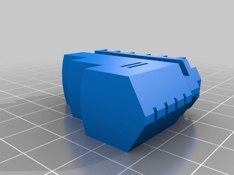 , a manufacturer of low cost injection molding machines, to test and demonstrate the viability of SLA injection mold printing.
Fig. 2 : 3D printed molds in aluminum frames.
METHOD
Both clear and high temperature resins can be used to print small functional forms, with high temperature resins offering compatibility with a wider temperature range of
thermoplastic melts. Formlabs Clear Resin was chosen for its strength, high detail and smooth surface Clear Resin is preferred for its transparency as you can easily see when forms are being filled, but any of the standard Formlabs Resins (clear, white, black and grey) can also be used as they have similar mechanical properties. The plates were printed with a layer height of 100 µm and took approximately 5 hours per plate. Depending on the geometry, multiple shapes can be printed at once on the build platform to improve printing efficiency.
Fig. 3 : Printing setup in PreForm with cavities up.
Two forms were printed from transparent resin. Parts and subsequent molds were designed to match Galomb machine vise sizes, 1 in3 injection cylinder capacity, and Form 2 build volume. supports were polished.
The parts were then cured for one hour under a 405 nm UV lamp to achieve full mechanical strength and rigidity. For a better understanding of the impact of post-curing on parts, see the Formlabs UV post-curing booklet.
Fig. 4 : 3D printed molds in aluminum frames and die-cast parts.
The first was a large Formlabs butterfly logo and the second was four small Formlabs butterfly logos. Both molds had a cavity, narrow inlets, and sprue at the point of injection and were designed in Solidworks. The molds were inserted into aluminum frames to provide protection from the downward pressure and heating of the injection nozzle. Aluminum frames can also prevent the shape from deforming after repeated use. The frames shown in figures 2 and 4 were custom made by Whittaker Engineering in Scotland, but standard aluminum frames are readily available on request from injection molding machine manufacturers.
Plastic pellets can be purchased online or from suppliers such as IASCO-TESCO. To create different colors, the molten plastic was pre-mixed with powdered dyes prior to injection.
Using a Model-B100 benchtop injection molding machine, Galomb tested printing plates with 25 shots of LDPE. LDPE melts at approximately 325°F (163°C) and was chosen for its low melting point. Of note, Formlabs Clear Resin has an HDT at 0.45 MPa 73.1 ºC after post-cure (see Material Data Sheet). HDT is a measure of the thermal properties of a material, but does not rule it out for use, although LDPE has a higher melt temperature. Whether your 3D printed mold will withstand the injection molding process depends on the melt temperature of the injection material, part geometry, and cooling and cycle times.
RESULTS FOR CLEAR POLYMER
After 25 injections of LDPE, there was no noticeable deterioration in the surface of the molds (chips, cracks or scratches). LDPE is not prone to sticking to polymer molds when tested, but other plastics may require the use of a mold remover to assist in part removal. Adhesion of the part to the mold can cause mold wear during ejection. Release agent is widely available, and silicone release agent is compatible with Formlabs standard and high temperature resins.
The cycle time for each injection was approximately three minutes. This process was accelerated by using compressed air to cool the mold. Cyclic injection into forms printed on the Form 2 causes the form to heat up. To counteract this, the cooling time between open mold cycles must be increased. While the mold cannot deform, too much residual heat will reduce molding success if the mold is opened too early. Galomb also improved molding success by etching shallow (0.05 mm deep) vent holes (not shown) leading from cavity edge to mold edge so that air does not enter the cavity during injection.
Some of the injections showed a leak in the parting line due to deformation of the polymer mold during the cooling phase after several injections. Increasing the clamping force in the vise can help mitigate leakage, as can polishing the parting plane of the mold to make it as flat as possible. Galomb proposed incorporating channels into the mold design to include metal tubes and fill them with aluminum epoxy, as a strategy to strengthen the mold, reduce warping, and improve cooling time.
Fig. 5 : A range of injection molding parts made using 3D printed molds.
FURTHER TESTING WITH HIGH TEMPERATURE POLYMER
Clear resin molds have been successfully tested using LDPE, which has a relatively low melt temperature. Higher melt temperatures can cause thermal shock in clear resin printed parts, which manifests itself as a deformed mold surface.
Transparent resin molds experience thermal shock when exposed to higher temperature molten plastic.
Formlabs printed the shape of a USB device case in High Temp Resin to test
| Melting Point | Plastics | High Temp Polymer (HDT at 0.45 MPa = 289° C) | Clear Resin (HDT at 0. |  45 MPa = 73.1°C) 45 MPa = 73.1°C) |
| LDPE | 163 °C | ||
| PP | 177 °C | ||
| TPE | 177 °C | ||
| PLA | 180 °C | ||
| ABS | 204 °C | ||
| HDPE | 204 °C | ||
| EVA | 204 °C | ||
| Polystyrene | 226 °C |
High temperature polymer molds showed no temperature degradation at the mold surface for any of the tested plastics.
*DURABLE RESIN polymer is under development and final specifications are subject to change.
High Temp and Standard are the polymers best suited for molding. Of the Formlabs resins, High Temp has the highest HDT at 0.45 MPa and low thermal expansion. It is also the stiffest material with the highest stretch factor.
The relatively high stiffness of High Temp Resin means that the mold will not deform when the part is removed. This makes the use of a release agent especially important for removing parts molded from rigid plastics such as polystyrene.
GENERAL TROUBLESHOOTING
Form overflow leak.
Leakage occurs when the injected plastic is forced out between the two mold halves. This can happen when the shape is overflowing, or if the split plane is not completely flat. Adding thin exit ports to the mold can help mitigate leakage from overpressure within the mold, facilitate part removal, and eliminate entrapped air that can cause bubbles in the molded part. Although not shown, the plates were tested without the aluminum frame.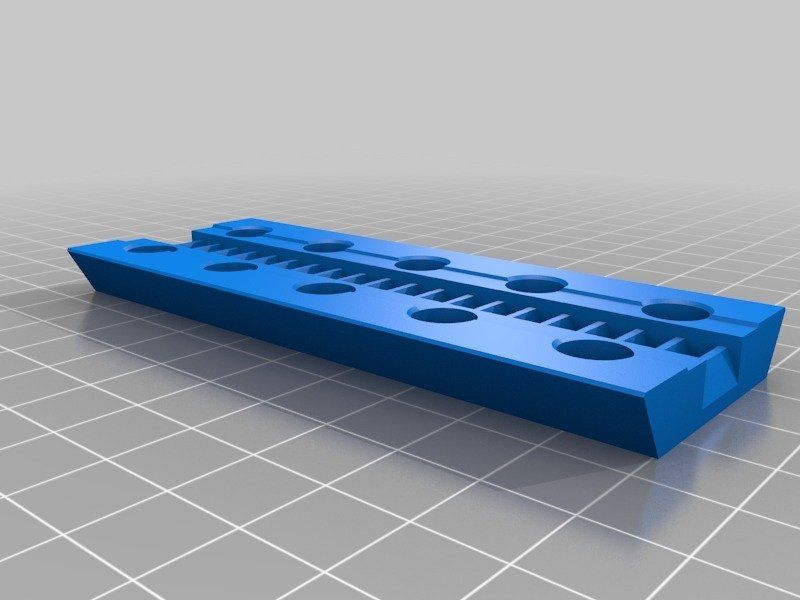 The downside to this approach is that these parts use more material, which increases printing cost and time, and the forms can be more prone to warping. With this method, a steel washer placed between the printing plate and the nozzle of the injection molding machine protects the print from direct contact and helps distribute forces. In addition, pre-sealing the injection molding cylinder against a metal block helps ensure there are no air pockets to disrupt the plastic flow.
Printed lines visible on some parts; this can be reduced by printing the form with a lower layer height. The plates used in this study were printed at 100 µm, but 50 or 25 µm could also be used. This will improve the cleanliness of the plate surface, but increase print time and reduce tank life.
Final USB device case molded from high temperature resin.
DESIGN INSTRUCTIONS.
When designing a form, consider what will print successfully and what will form successfully.
- Adding one to three degrees of recess on surfaces perpendicular to the direction of the recess will allow easier part removal and minimize mold degradation. Fillets should be applied to the inside edges to reduce buckling from internal plastic stress and facilitate removal of the part.
- Embossed and engraved parts must be offset from the surface by at least 1 mm.
- If you plan on using an aluminum frame, The surfaces of the split planes can be polished with fine sandpaper to reduce flare. add an extra 12mm thick plate to the back of the mold plate to account for compressive forces and ensure complete sealing.
- Be sure to orient the mold halves in the PreForm so that the cavity is facing up. This will prevent reference marks inside the cavity and make post-print processing easier.
90° angle
2° recess
Optimum condition 2° recess and rounding.
PROCESS SUMMARY
STEP 1:
Part design in CAD.
STEP 2
Mold design in CAD.
STEP 3
3D print the forms on Form 2.
STEP 4
Remove support material from molds.
STEP 5
Insert the plastic into the mould.
STEP 6
Remove the part from the mold.
3D Printing DLP LCD SLA Resin - Guide to Stereolithography
The effects of photopolymerization transform liquid materials into solid objects. SLA is widely used to create models, prototypes, templates and finished parts in a number of industries - in industrial production, in dentistry, in jewelry, in modeling, in education.
In this comprehensive resource, you will learn about the different SLA systems, the different materials and their characteristics, and how SLA compares to other technologies available on the market.
A Brief History
The SLA process was first demonstrated in the early 1970s when Japanese researcher Dr. Hideo Kodama invented the modern layered approach to stereolithography by using ultraviolet light to cure photosensitive polymers. The term "stereolithography" itself was coined by Charles (Chuck) W. Hull, who patented the technology in 1986 and for its commercial promotion founded the company 3D Systems. Hull described the technique as creating three-dimensional objects by sequentially printing thin layers from bottom to top with a material that is cured with ultraviolet light. The definition was later extended to include any material capable of curing and changing its physical properties.
Today, 3D printing and additive manufacturing refers to many different processes that differ in layer methods, materials and hardware.
The patent began to expire towards the end of the 2000s, at which time desktop 3D printers appeared on the scene and expanded access to the technology, offering to start with the introduction of fusing deposition (FDM) to desktop platforms. Although this low-cost, extrusion-based technology has contributed to the widespread adoption of 3D printing, the quality of the resulting parts has limited its use, as repeatable and high-precision results have proven to be critical in professional applications.
Prototypes of the Form 1, the first desktop SLA 3D printer
The SLA soon followed FDM's path to the desktop, with the technology appropriately modified by Formlabs in 2011. There was hope that high-resolution printing, previously only possible on industrial systems, would come in a much smaller form factor and at a more affordable price, allowing for a wide range of materials. These capabilities have made 3D printing accessible to a range of applications, including engineering, consumer goods design and manufacturing, dentistry, and jewelry.
SLA systems
SLA technology belongs to the family of additive bath photopolymerization technologies. Accordingly, SLA printers are built around this principle: a light source (an ultraviolet laser or a projector) is used to turn a liquid polymer into a hardened plastic. The main physical difference between the devices is in the configuration of the main components, such as the light source, work platform, and resin container.
How stereolithography works
Normal (Right-Side Up) SLA process
Normal (Right-Side Up) SLA process units are built around a large liquid photopolymer tank and work platform. The ultraviolet laser is focused on the polymer surface, passing along the profile of the 3D model. Then the platform is lowered a distance equal to the thickness of one layer, and the spatula with photopolymer passes over the bath to replenish it with material. Layers are built one on top of the other until the part is complete.
This approach is used mainly in large industrial systems and was the standard for stereolithography until the advent of desktop solutions. Its advantages lie in the ability to create very large 3D objects, low stress on the part during the printing process, high detail and clarity.
Due to the large plant size, maintenance requirements and volume of material, normal SLA systems require a large initial investment and are expensive to operate. The entire print area must be filled with resin, often 10-100 liters or more, resulting in a lot of maintenance, filtering and material replacement. Such machines are very sensitive to their position in space, any misalignment can cause the paddle with the polymer to overturn the part, i.e. to a fatal print failure.
Upside-Down SLA process
As the name implies, the inverted stereolithography process is the reverse process. This method uses a tank with a transparent bottom and a non-adhesive (to which it does not stick) surface, which acts as a substrate for the curable liquid polymer, allowing free separation from the newly created layer. The platform is immersed in the polymer tank so that there is a space to the bottom equal to the thickness of the layer or the last completed layer.
Through a system of mirrors, an ultraviolet laser beam is directed by two mirror galvanometers to a point with the desired coordinates, focusing from below, through the bottom of the bath, onto the curable photopolymer layer. As a result of the vertical movement of the platform and the horizontal movement of the tank, the cured layer is separated from the bottom of the tank, and the platform rises, leaving a new layer of resin underneath. The process is repeated until the print is complete. In more advanced systems, the tank is heated to provide temperature control, and a paddle is run along the tank under the new layer to circulate the polymer and remove any semi-cured residue.
The advantage of this inverted approach is that the size of the created object can exceed the volume of the tank, since the apparatus only needs to have enough material to permanently cover the bottom of the bath. This typically facilitates maintenance, cleaning, material replacement, and significantly reduces machine size and cost, and allows SLA technology to be ported to desktop systems.
Inverted SLA systems have their own set of limitations. Due to the cohesive forces acting on the object as it separates from the tank surface, the working volume is limited and more and more support structures are needed to keep the part above the work platform. Adhesion forces also limit the use of more ductile materials, with a Shore hardness of less than 70 A, as the support structures also become ductile.
About support structures
Both normal and inverted SLA systems in most cases, depending on the design, require the use of support structures.
In normal systems, these structures hold the parts in position, ensuring that the material is correctly placed on them, as well as resisting lateral pressure when the polymer blade moves. In inverted SLAs, supports are used to attach overhanging elements to the platform, preventing layers from separating under the influence of gravity and adhesion.
In both SLA systems, support structures are used to attach parts to the work platform.
Most programs create their own support structures during the preparation of 3D models, but manual adjustment may be required. After the printing process is completed, these supports must be removed and the object subjected to finishing.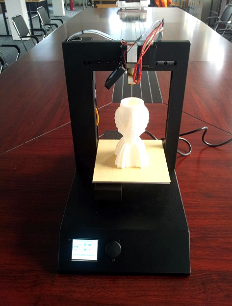
Comparison of SLA systems
| Desktop SLA Inverted | Industrial SLA Normal | |
| Price | From $3500 | $60,000 – $1,000,000+ |
| Displacement | Up to 145 x 145 x 175 mm | Up to 1500 × 750 × 550 mm |
| Pros | Affordable | Large displacement |
| Cons | Medium displacement | Expensive in materials Expensive equipment |
Comparison of desktop SLA printers based on Formlabs and industrial SLA systems from 3D Systems.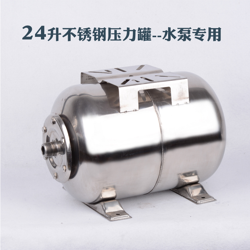
Materials
SLA 3D printers are a tool, but it is materials that allow stereolithography to create a wide range of functional parts for various industries. In this section, we will look at the photopolymerization process and its raw materials, polymers, both in terms of their unique properties and in terms of various combinations for specific applications.
Polymerization process
Plastics are made up of long carbon chains. The shorter the chain, the less durable the plastic and the more fluid. A polymer is, in this case, a resin consisting of one or more (up to several thousand) short carbon chains. It has all the components of the final plastic, but is not yet completely polymerized. When such a resin is exposed to ultraviolet light, its carbon chains interlock, forming a longer and therefore stronger structure. After enough chains have reacted, a solid part is obtained.
Steps of the polymerization process
Let's take a closer look at the process. The chains of monomers and oligomers in a polymer have active molecular groups at their ends. When UV radiation falls on the polymer, the photoinitiator molecule breaks into two parts, and the bond connecting them forms two very reactive radicals. These molecules donate reactive radicals to the active groups of monomer and oligomer chains, which in turn react with other active groups to form longer chains. As the chains lengthen and cross-links occur, the plastic begins to harden. The entire process of transition from liquid to highly polymerized solid state takes place in milliseconds.
Characteristics of polymers and plastics
Different polymers are composed of different main and side groups - different combinations of long and short monomers, oligomers, photoinitiators and additives. This provides unique opportunities to create various formulas with a wide range of optical, mechanical and thermal properties - from clear transparent to colored plastics, from flexible to rigid, from viscous to heat resistant.
Photopolymer resin formulation
| Component | Role |
| Monomers and oligomers | Polymer backbone, carbon chains that later form a solid. |
| Photoinitiator | Molecules that react when exposed to ultraviolet light to initiate a reaction. |
| Additives | Visual and functional additions such as pigments and inks. |
Isotropy and anisotropy
Due to the layered nature of 3D printing technologies, in some cases the properties of the object created in this way differ to a certain extent depending on the direction - this is called anisotropy. For example, a 3D printed object may have different tensile strength or stiffness in the X, Y, and Z directions.
During SLA 3D printing, polymer components form covalent bonds. This provides high lateral strength, but the polymerization reaction is not brought to completion. The printing process is modulated in such a way that the layer is maintained in a semi-reacted state, which he calls "green". The green state differs from the fully cured state in one important way: there are still polymerizable groups on the surface that form covalent bonds with the subsequent layer.
When this subsequent layer cures, the groups of the previous layer are involved in the polymerization reaction, forming not only lateral covalent bonds, but also bonds with the previous layer. This means that at the molecular level, in terms of chemical bonds, there is no or almost no difference along the spatial axes. Any continuous object printed using SLA technology is isotropic.
With SLA printing, there is no difference along the spatial axes in terms of chemical bonds. Any continuous object printed using SLA technology is a continuous polymer network.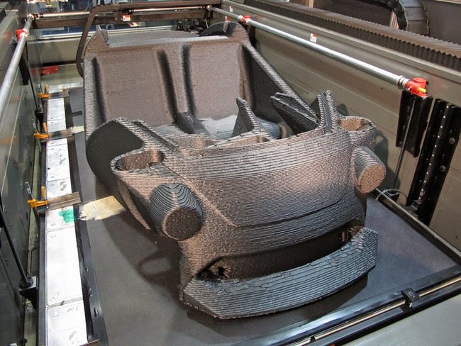
Isotropy has both mechanical and optical advantages. Isotropic parts are ideal for prototyping as they reflect some of the properties of traditional injection molded thermoplastics and do not suffer from delamination and porosity. The formation of chemical bonds and the absence of visible layers within the object allow optically clear parts to be printed.
Post-curing
When the stereolithography process is completed, the printed part remains on the build platform in the aforementioned "green" state. Although it already has the final shape and appearance, the polymerization reaction is not completed, so that the mechanical and thermal properties are not yet fully formed.
UV SLA prints. UV curing completes the polymerization and stabilizes the mechanical properties. Photo: formlabs.com
Additional UV curing completes polymerization and stabilizes mechanical properties. This allows the part to achieve the highest possible strength and become more stable, which is especially important in the case of functional plastics for engineering, dentistry and jewelry. For example, successful burnout in a printed mold requires post-cure, and flexible parts also become stronger after post-cure.
Thermoset and thermoplastics
Photopolymer resins are thermoset plastics - as opposed to thermoplastics. Sounds similar, but features and applications can vary significantly. The main physical difference is that thermoplastics can be repeatedly melted to a liquid state and cooled back to a solid in different geometries, while thermoset plastics remain permanently in a solid state after post-cure.
The polymers in thermoset plastics cross-link with each other during the post-cure process, forming virtually irreversible chemical bonds. In the case of the most common thermoset plastics, post-curing is carried out by appropriate irradiation, often under high pressure; in stereolithography, this process is excited by light with the participation of a photoinitiator. The thermoplastic granules soften and liquefy under the influence of temperature, and the process is completely reversible, since chemical bonds are not formed.
SLA Materials by Application
Stereolithography materials are typically created for specific applications or industries. Due to the nature of the techniques and processes used, proprietary materials are usually of limited use in specific SLA systems. Below, we'll introduce Formlabs' selection of desktop SLA printer media.
Standard
Interchangeable camera made entirely from Standard polymers, including optically clear lenses. Photo: formlabs.com
Standard resins provide high resolution, fine detail and a smooth surface right out of the printer. While post-cure is recommended, it is not always required, making these resins ideal for rapid prototyping, product development, and general modeling.
Engineering
Objects printed with Engineering resins, including thermoforming and injection moulds, shoe insoles and consumer goods. Photo: formlabs.com
Engineering Polymers simulates a variety of molded plastics, helping planners and designers with concepts, prototypes, test pieces, and finished products. With characteristics such as strength, wear resistance, flexibility or heat resistance, these plastics are used to create prefabricated and solid functional objects, touch surfaces, consumer goods.
Dental
Dental resin model, biocompatible dental implant printed on Form 2. Photo: formlabs.com
Dental materials allow dental laboratories and clinics to create a variety of personalized dental products on site. Such products are modeled according to the results of computed tomographic scanning of the patient's oral cavity. Specific applications include orthodontics, diagnostics, teaching models, as well as biocompatible items such as surgical instruments and drill guides.
Jewelry
Castable resin jewelry and finished ring. Photo: formlabs.com
SLA is ideal for prototyping and molding fine detail jewelry. Conventional modeling resins are recommended for prototyping to create low cost fittings and test pieces to match customer requirements before the part is cast. Castable resins are designed directly for mold making, enabling jewelers and foundries to move from digital design to 3D printing straight away.
Experimental
Soap dish printed with Ceramic resin and finished for a particularly aesthetic look. Photo: formlabs.com
Different formulas of polymers with additives and composites open up new possibilities for creating experimental materials. The Ceramic polymer allows, after further processing, to obtain aesthetically looking objects that are indistinguishable from traditional ceramic. After firing, the printouts turn into pure ceramic, ready for glazing.
Benefits of a Desktop SLA Printer
To help you decide if the SLA process is right for you, we compare stereolithography with traditional manufacturing methods and other additive technologies.
High resolution and smooth surface
SLA technology immediately produces parts with a finished smooth surface. It is ideal for applications that require a perfect finish and reduces production time as parts can be easily refinished, polished and painted if desired.
The usual way to determine the resolution of a 3D printer is to look at the layer height (vertical thickness). On the Form 2 printer, it can be set from 25 to 100 microns, taking into account speed and quality. For comparison: FDM and SLS printers have a characteristic layer thickness of 100 to 300 microns. But 100 micron parts printed on an FDM or SLS printer look different from SLA parts printed at the same resolution. SLA prints have a smoother surface immediately out of the printer due to the fact that the walls of the outer perimeter are smoother due to the interaction of each printed layer with the previous ones, which smooths out the ladder effect. Layers can often be seen in FDM printouts, while SLS has a grainy structure from the sintered powder.
Rooks printed at 100µ layer thickness on benchtop and industrial FDM, benchtop SLA (Form 2), industrial SLA and industrial SLS. Photo: formlabs.com
The minimum possible detail is also less in the case of SLA: 140 microns from the laser spot for Form 2, 350 microns for industrial SLS printers, 250-800 microns from the nozzle of FDM machines.
Learn more about 3D printing resolution
Accuracy and repeatability
SLA printers can create precise, repeatable parts. This is especially important for functional applications such as design assemblies, jewelry molds, or scanned dental products.
The combination of the heated plastic tank and the enclosed space in which the print is made provides nearly identical conditions at every point. Greater accuracy is also due to the lower printing temperature compared to thermoplastic technologies that melt the raw material. Because SLA uses light rather than heat, the printing process occurs at nearly room temperature, and printed objects are free from thermal expansion and contraction artifacts.
In general, SLA print accuracy is between 50 and 200 microns, depending on size, resin, model geometry, and generated supports. In recent tests on the Form 2, 95% of printouts had size deviations of 240 microns or less.
Design freedom
SLA offers the greatest design freedom of any 3D printing technology. Depending on the geometry of the part, concave and convex elements can be made with an accuracy of 300 microns or better. This is especially important for complex applications such as sculptures with small elements and fine jewelry.
In the case of stereolithography, there is no need to adapt the model for 3D printing. Prototypes can be designed with production in mind. This ensures a seamless transition from prototype to traditional technologies such as machining or casting.
SLA printouts are easy to clean and finish. The internal ducts in the plastic are easily flushed out, allowing the creation of microchannels or cavities not possible with any other 3D printing process.
Micro channels for flow and mixing of liquids, printed with Standard Clear plastic. Photo: formlabs.com
Rapid prototyping with rapid iterations
Stereolithography helps engineers and designers quickly improve the look and feel of a project. Mechanisms and designs can be checked and modified without problems within a few days, which greatly helps to speed up development and avoid expensive tooling.
Successive iterations of Sutrue, an automated surgical instrument prototyped on Formlabs SLA printers. Photo: formlabs.com
Desktop SLAs are highly scalable, dramatically increasing performance and reducing user wait times. Teams working in different locations can work independently on the same project, sharing physical objects through digital channels and printing them on the same printers.
Functional parts for a wide range of applications
SLA plastics offer a wide range of features that are suitable for applications from engineering to dentistry and jewelry. Materials can be heat-resistant, biocompatible, optically pure, and meet the parameters of engineering plastics.
The chemical bonds formed between the layers of the SLA object allow the creation of completely dense, water and air tight parts that are isotropic, that is, have equal strength in all directions.
Pricing and Benefits
Accurate prototypes, fast iterations, and early error detection all lead to a better end result and reduce risk when moving from prototyping to production. In industry, SLA technology reduces the need for expensive machining by making small batches and customized products available. This also applies to the construction of bridges, and the manufacture of jewelry or dental products.
Industrial SLA printers start at $80,000 and require trained personnel and a mandatory service contract. SLA desktop printers offer the quality and functionality of industrial systems while being easy to use, in a small footprint. They cost from $3500.
Compared to outsourced ordering or traditional machining, home 3D printing reduces costs by 50-90% considering materials, tanks, accessories, maintenance, labor and wear. In the case of desktop SLAs, the characteristic time for obtaining a result is hours, not days or weeks, as when ordering the same project on the side.
Technology Comparison
There are three common plastic 3D printing technologies today. In layer-by-layer deposition (FDM), thermoplastic filaments are laid out on a work surface, in stereolithography (SLA), a liquid photopolymer resin hardens under the influence of a light source, in selective laser sintering (SLS), a powdered material is sintered by a laser.
Each technology has its own advantages and disadvantages, so each is recommended for different applications.
| FDM | Stereolithography (SLA) | Selective Laser Sintering (SLS) | |
| Pros | Fast | Great value | Robust functional parts |
| Cons | Low accuracy | Limited modeling space | Expensive equipment |
| Applications | Cheap Rapid Prototyping | Functional Prototyping | Functional prototyping |
| Price | Mid-range desktop printers from $2000, industrial systems from $20,000. | Professional desktop printers from $2000, large scale industrial systems from $80,000. | Industrial printers - from $100,000. |
Printing process
Now that we know the theory behind stereolithography, let's look at the printing process on a desktop SLA printer.
Project
Use a regular CAD program to design your model and export the result in a 3D printable format. Photo: formlabs.com
As with any other 3D printing process, SLA starts with 3D modeling, the mathematical representation of a 3D surface. This can be done with a CAD program or based on 3D scan data. The model is then exported to a .STL or .OBJ file that is understood by the program that prepares the data for the 3D printer.
Preparation
Prepare your model in SLA 3D printer software. Photo: formlabs.com
Each SLA printer comes with a program for setting print parameters and cutting the digital model into layers for printing. In the settings, you can change the orientation of the object, support structures, layer thickness and material. When setup is complete, the software sends instructions to the printer wirelessly or via cable.
Printing
Stereolithographic printing process. Photo: formlabs.com
After a quick confirmation of the correct settings, the printing process begins, and the printer can be left to itself until the job is completed. In printers with a cartridge system, material is added automatically, in other cases and with large volumes, this may require intervention.
Cleaning
Clean printout with isopropyl alcohol (IPA) to remove uncured plastic. Photo: formlabs.com
When the printing process is complete, the build platform can be removed from the printer. The printout should be cleaned with isopropyl alcohol (IPA) to remove uncured plastic from the surface.
Hardening
Post-harden part to improve material quality.


