3D printed electrical connectors
Is It Possible to Produce 3D Printed Electrical Connectors?
Search
Search
Applications
Additively Manufactured Electrical Connectors - Are We There Yet?
Numerous industries around us are in the midst of a movement towards electrification. An excellent example of this, and the one likely to have one of the highest impacts on the global market, is the passenger vehicle. Tesla and Cybertruck aside, major automobile manufacturers are contributing to the development of our electric vehicle (EV) future. Beyond that, automotive OEMs continue to introduce more computer systems, accessories, and other features that rely on electronic interconnectivity to function. Furthermore, new industries like delivery drones and autonomous robots continue to emerge, preparing to surpass the niche category label and enter into the mainstream global market. Widespread infrastructure will be required to support this approaching electrification, which will inevitably create similar growth in associated supporting markets.
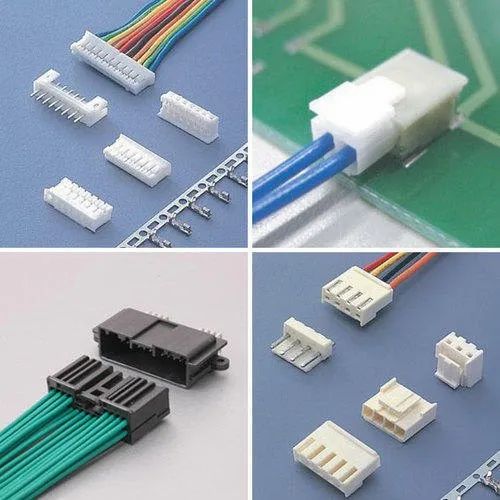
As these market shifts continue, more players and products will emerge and electrical connector manufacturers will need to remain nimble to continue to support existing and new customers. OEMs like the four North American connector giants (TE Connectivity, Aptiv, Molex, and Amphenol) may be serving a market that is characterized by a wider range of products that are manufactured at smaller volumes. Electrical connector shells and housings are mostly an injection molded product. In the case of injection molding, the most expensive part and longest lead time tends to be the manufacturing of the injection mold hard tooling. At high volumes, the cost of the tool is amortized over a large volume of parts, and makes excellent economical sense. However, to make a similar part at small volumes, the costly tool can be expensive enough to make a small-batch product run not economically viable. Most EV manufacturers are manufacturing less than 200,000 units per year, with more and more players entering this market. Finding new solutions will be essential to support the growth of these markets.
Fortify’s approach is modeled after fiber-reinforced injection molded plastic parts. Fiber reinforcement in a molded part shows 20-100% increase in mechanical properties such as strength, stiffness, and HDT. This proven uptick in material performance is why the market for reinforced plastic parts continues to grow. Fortify is applying this same methodology to end use manufacturing applications like electrical connectors. By adding reinforced fibers to the right materials during the printing process, Fortify can realize increases in electro-mechanical properties needed for high performance parts while also meeting the economic requirements of small volume manufacturing.
Small volumes and bespoke solutions are a perfect fit for 3D printing. Employing 3D printing can introduce both cost and lead time efficiencies. Smart and effective implementation of 3D printing onto the factory floor will enable economically viable low volume manufacturing runs and also shorten lead times by eliminating the need for tooling altogether.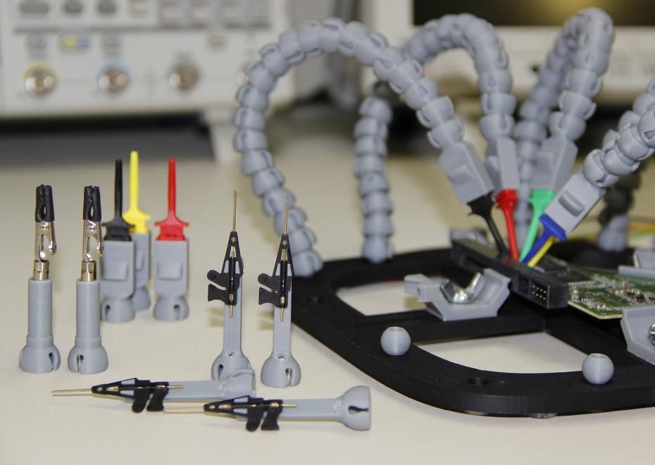
The AM industry has started to engage with this product market fit. Collaborations with 3D printing companies and connector companies have started to see some real progress, however, challenges still remain. 3D printing OEMs are working to find THE breakthrough material + process combination that will eliminate the barrier to full AM adoption for production applications. What’s holding 3D printing back? In the case of electrical connectors, the culprit is a combination of material properties and print resolution.
Can 3D Printed Connectors Meet Auto Industry Standards?Looking closely at standard automotive electrical connectors, many housings and shells are made primarily from glass-filled engineering grade thermoplastics like PBT, PPS, or nylon. There are no players in the field who can directly 3D print PBT or PPS, but nylon has been available in 3D printing for decades – there are also glass-filled options available. For FDM and SLS, the two major commercial thermoplastic additive manufacturing technologies, there are severe limitations tied to the unavoidable physics of the technology.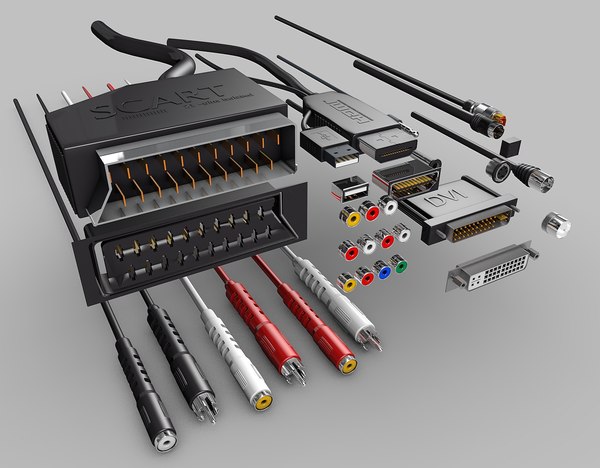 These processes cannot meet the resolution, surface finish, wall thickness, hole size, and tolerance requirements that are demanded of a commercial multi-cavity electrical connector. Some DLP and SLA solutions have the capability to reach these resolution requirements, but they can not print with the industry-standard thermoplastic materials like nylon and PBT, or match their properties that are critical for this application.
There are DLP and SLA companies working hard to improve their resin formulations that come closer to the high level requirements of electrical connector applications. The ability to print a part that is tough enough to survive several drops on concrete factory floors yet is also capable of surviving extended thermal cycling up to 150℃ is an engineering challenge for photopolymer material scientists. Achieving specific characteristics like high temperature resistance combined with increased toughness can unlock access to big commercial opportunities for applications in aggressive environments – like in an engine compartment or areas exposed to dramatic weather conditions.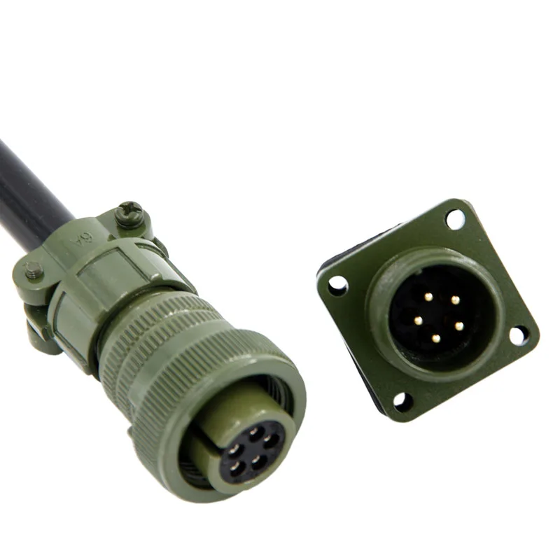 Chemical manufacturers like BASF, DSM, and Henkel have developed high temperature and V0 flammability rating engineering photopolymers with an eye on tackling the tough automotive electrical connector requirements, but a complete solution is not yet available. If our industry continues to focus on improving material properties in photocurable thermoset systems, we will be able to achieve both the resolution and material properties necessary for electrical connectors. Fortify is working with material partners to improve material performance for production parts, including electrical connectors, to meet automotive (and other industry) requirements.
With the global shift towards electrification of high value products, and continuous development of 3D printable materials teetering on the precipice of full engineering-level performance characteristics, the market is prepared for a solution. With continued collaboration between the 3D printing material developers and electrical connector OEMS, it won’t be long before we start to see real 3D printed solutions enter into this global market.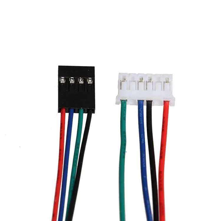
If you have an electrical connector application you would like to explore reach out to us today!
This post was written by Sr. Applications Engineer, Phil Lambert.
3D Printing Connectors - The Samtec Blog
In a time of 3D printers in many engineers’ (and future engineers) shops, labs, or basements, we keep looking for ways to produce parts faster. You may be asking how far away are we from 3D printing connectors. When is Samtec going to replace all its automation with a bunch of shiny 3D printers? Can I get my parts faster if I make them myself?
As a director of a regional makerspace, we deal with 3D printers every day and get questions from every direction of “what can I make with a 3D printer right now!?” Our typical answer back is “what can’t you make?!” We then must frame up the speed, scale, and material options that are easily available to makers. If you are interested in a bit of history about 3D printing, check out this article by Sculpteo.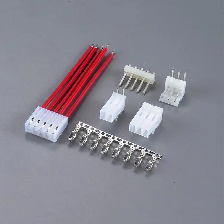
When I put my Samtec hat back on and think of new ways to produce parts, I tend to run into a few issues. At least issues with the full assembly. Prototyping and assembly support are a couple of ways we currently use 3D printing and additive manufacturing today. I will expand on each of those applications below and how Samtec can use alternative technologies to take care of our customers.
PrototypingChecking the form and fit of a component or feature in an application is typically a gateway into using 3d printing. The overall size and tolerance would be your starting point on the type of 3D printer you will need. Samtec will typically migrate to an SLA (Stereolithography) 3D printing technique for our connector development. This has always given us better resolution for insulator features and can typically handle very light assembly techniques to build initial samples. Typically, we cannot use these parts for functional test, but they can help prepare automation and marketing for what they need to do next.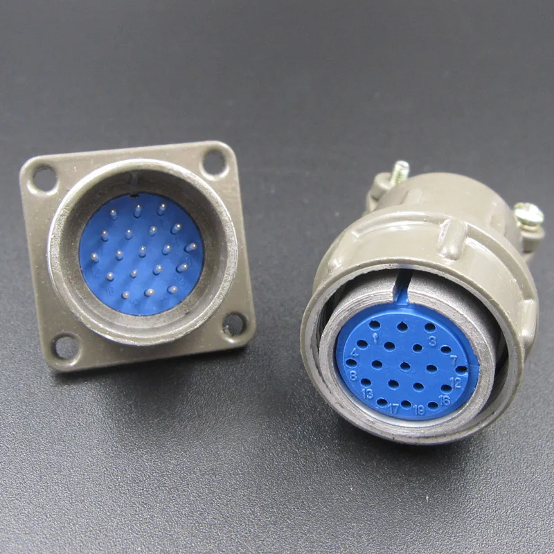 Some of our favorite vendors to work with are ProtoLabs and Xometry. They support 3D printing applications, as well as, many other advanced manufacturing techniques for prototypes and low volume builds.
We do not typically 3D print connector pins, but have dabbled with this process in the past. The problem with this is similar to the plastics. It can give you a form and fit, but not the function. Currently, available metals and alloys just do not have the same spring properties of traditional materials.
Tooling and Assembly Support
Over the years, Samtec has taken pride in the flexibility of our designs and engineering talents. Between 20%-30% of our business is making modifications of ASP’s (Altered Standard Products) for a specific customer need. With this style of business we need a flexible processes and tooling that can be manipulated on the fly. We have used plastic 3D Printed guides and fixtures to position assemblies in tooling. We have used 3D printed dies to create custom thermoformed plastic shells for packaging.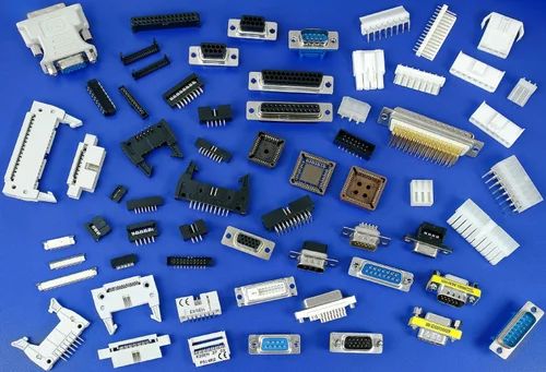 Metal 3D printed components may be used for higher wear applications. We have found it helpful to evaluate a few different methods by working with a regional rep who carries multiple options. (One we have worked with on multiple occasions is Integrated Machinery System) Some metal tools we have been able to use right out of the machines, where others needed a bit of post processing.
We continue to keep our eyes on combining technologies, new materials, composites, and faster advanced manufacturing techniques. Every time we find something interesting, our automation and operations team step up and innovate. With Samtec’s speed, built in flexibility, and innovations on our website, we like to think we are keeping pace with the in-home replicators. If you have not ever used Samtec’s sample program, we can typically get you not only a representation of your assembly, but the actual fully functional assembly as a sample within 24 hours. If that is not fast enough to check your design, we have downloadable 3D models on most of our assemblies available instantly (supporting nearly 100 types of software and file formats).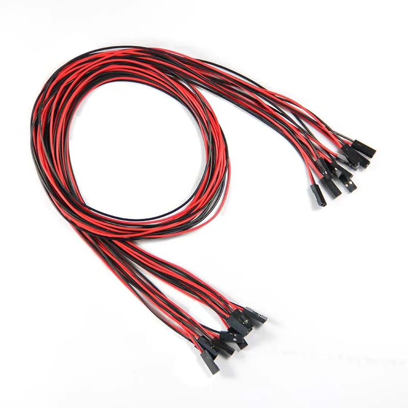
Still Not Enough!
Do you need a larger volume faster? Many 3D printers can print multiple parts at the same time, but each addition adds time to the process. What about using optimized advanced manufacturing and logistics at their finest? Samtec Reserve™ is a new designation that we’ve provided on over 200,000 (and growing quickly) connectors and cables. These are popular stocked parts that are guaranteed to ship in 1-day!
Conclusion3D printing and other additive technologies are amazing and evolving how we build and design products. The speed of other advanced manufacturing techniques is also evolving. Where we can not fully 3d print a connector right now the utilization of 3D printing in the design and development process definitely speeds things up and helps us bring new solutions to you faster.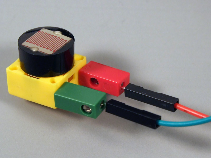
2 Story House
Candy & Food
Heart
Car
How to 3d print another 3d printer
Already have a 3D printer? Want another one?!
Why is this needed?
Well, let's say you have your own large printer and you can print fairly large objects. Do you believe in the idea of the reprap movement, the printer should be able to reproduce itself!
Or you want to challenge yourself and finally understand how the 3D printer works.
Or your current 3D printer is just sitting around gathering dust in the corner of the room, because you have already printed everything that came to mind, and the most difficult task that worries all 3d printing professionals is how to clone existing equipment on itself.
Step 1: Preface
Let's be honest. .. the is not the ultra cheap printer. This is not Chery 3D printer for $60. This not is a way to save money or time. This is not first printer.
Now let's talk about what is .
B 3Dtje mini 3D printer is:
- Damn easy to print
- Printed parts from PLA
- Everything fits within 200x200 print volume
- Most parts can be printed in 100x100 print volume
- Most parts are printed without supports , only in some cases they may be needed to improve quality
- Very few few needed tools
- Unlike most crafts that require a laser cutter, CNC
- You can probably get away with a drill and a hacksaw to prepare 2 rods of the required size
- No source of MDF, or wood, or acrylic sheets or aluminum profiles, which can be expensive
- A Prusa i3 Clone
- This design is not new, nothing revolutionary, but it is reliable, prints well and works with any slicer
- Open source
- All model files can be downloaded free of charge
- You can download them and modify them as you like
- You can even sell them if you need to!
- Simple and interesting printing
- 19 models
- All parts are different and look very interesting together
- Easy to assemble
- All parts are connected with M3 screws and nuts.
- Cutting 2 to 4 metal rails
- Some 3d printed parts are assembled intuitively , you can even ignore photo
- All parts are connected with M3 screws and nuts.
- Really fucking cool!
- Small, portable, low moving parts! This printer can print fast! (when properly configured)
- This 3D printer you will DIY , completely!!
Let's get started!
Step 2: Prerequisites
You will need a 3D printer , well, or find someone with this device.
- Printable area must be at least 200x200mm XY and maybe 200mm Z if you want to print with refills
- PLA 1 kg, can be different, but this is the most convenient option
- I honestly don't know how much it will take. Likely 500g or so
- Tools
- Screwdrivers for screws
- Pliers, cleaning tools for printed objects (a clerical knife is sufficient)
- Metric drills for opening / cleaning the printed hole (you can also use a screwdriver)
- Knowledge on how to build a 3D printer from scratch
- These are not hard requirements, but knowing how to deal with common printer problems will reduce the amount of swearing when things aren't perfect the first time.
- If you understand firmware Marlin it would be very cool to talk about this, as there is a desire to improve some things.
- These are not hard requirements, but knowing how to deal with common printer problems will reduce the amount of swearing when things aren't perfect the first time.
Step 3: Parts
Right off the bat, I've made a list of exactly what you need and what you can buy to make the best possible quality. But it will be more expensive. Therefore, you choose which set to buy - in principle, they will not differ. In addition, you can order all this from China, it will be cheaper, but the wait will be longer. In any case, you need to look for all the components in English, so we take them from the table and, for example, insert in alliexexspress search .
The table is located at this link.
Step 4: Printing Parts
Now let's move on to the most interesting part, in my opinion - prototyping models. To be honest, I really like to print different things, you feel that you can handle any task when you have a 3d printer at hand.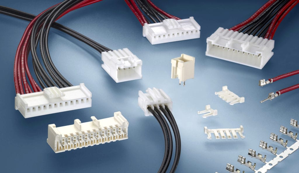 Okay, it's all lyrics.
Here is the project itself, where you can download 3d models for printer for free . Download and start preparing for printing.
The most important thing is to arrange the parts correctly on the table . The idea is to make the models have as few parts hanging in the air as possible. This will allow to drop support for . After all, they spoil the quality very much if you do slicing through Repetier Host with their auto-generation, and not draw them yourself.
You can watch a video showing the optimal arrangement of parts. Print settings I think you know how to do it, if not - there are articles about it with configuration files.
Step 5: Mounting
Let's assume that we have printed everything. Someone may have decided to use metal guides, buying them, for example, from IKEA, and cutting them into sections of the desired length. In any case, writing how to assemble this 3d printer does not make much sense, and it's too lazy, to be honest. In my opinion, there is nothing better than pictures!
Frame assembly
First, I'll lay out how our miracle should look like at the moment of medium readiness. Then we will see how the modules were assembled.
Assault Axis Y
This Axis drives The so -called bed . First we need to install the motor, put a pulley on it . Then we install a freely rotating pulley on the other side and measure 9 for them0003 belt .
And now we will install the bed itself, which will fasten the two ends of the belt to us. Just don't forget to tighten the pulleys and anything that isn't tight yet. The substrate will be massive and it will be inconvenient to crawl there already. The connection will require 200mm x 6mm bolts, so have them ready right away.
It should be noted that the belt must be very tight . This will greatly affect the print quality of . If you cannot do this at the time of assembly, you can use special tensioner . It's basically a simple spring. As for the axes, in this case they are printed, although this is far from mandatory, just the name of the project obliges))
X-axis assembly
Depending on your printer, you may need to make a hole with a 3mm drill in the belt tensioner. This hole should be quite free.
- Attach the motor to the end of the x axis with the connector down
- Attach 20T gear
- Insert 6mm rods 6mm x 180mm into the holes on the motor side. You need to cut these rods if you bought 200mm.
- Assemble the x-axis tensioner with either your own or printed tensioner bearing.
 Make sure the m3 nut is in the tensioner before proceeding.
 - Pass the belt from the left side (engine side), through the gearbox, through the idler bearing to the right side
- At this point, install belt tensioner to the right of the x-axis on the rods
- If you are happy with the length (make sure the x-axis of the tensioner is recessed quite a bit) you can cut the belt. Don't forget to leave extra belt length
- Attach LM6UU bearings in bottom bracket x
- All assembled, attach the straps to the carriage x
- Then it remains to adjust everything a little to make sure that nothing touches each other
Assembling the Z axis
Now we assemble the Z axis. If you have not installed the engines in the course of past work, it's time to do it. As you understand, they should stand on the left and on the right. We will install adapters for screw rods on them, where we will put them, holding them with a hexagon.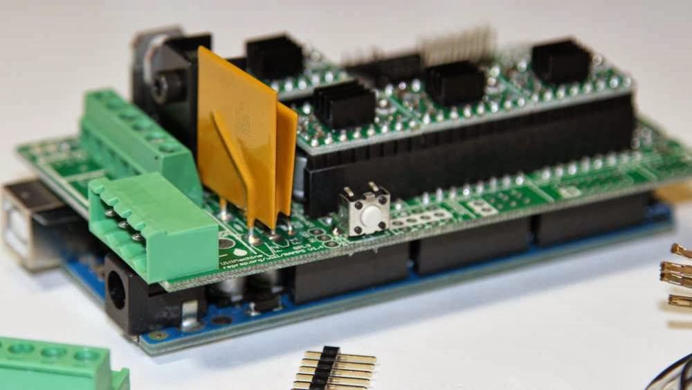
We stick the guides (parallel to the screw rods). We can say that we have finished assembling the case.
Step 6: Assembly of the electrical circuit.
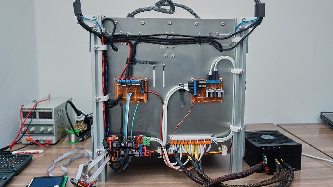
How to lay the wiring is everyone's business. Here the options will be shown in the photo, but it's up to you to decide. The most important thing is to connect everything correctly. I'll also lay out the scheme, but it's better to see how this is done in ordinary 3d printers. For example, in order not to go far, you can go over the following articles directly on this site:
-
Exploring the features of a 3D printer
-
3D printer setup and calibration
-
Ramps 1.4 connection in 3d printer
It is not necessary to read everything - you can see the key places from the pictures and delve into their study.
The picture below shows the green power terminal.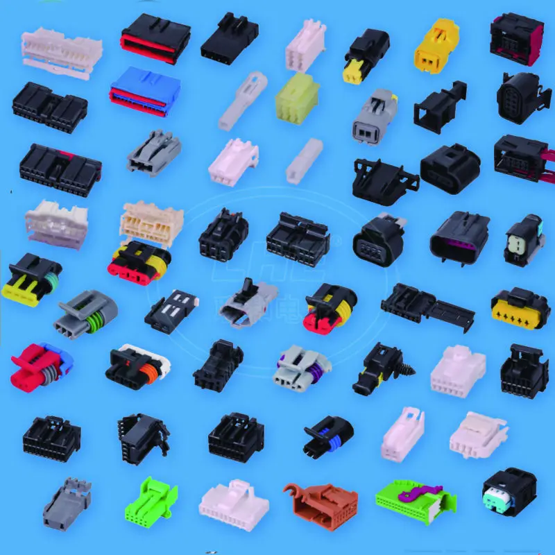 This is a very dangerous and unreliable thing that sometimes ignites - it is dangerous to leave a working 3d printer at home unattended. Therefore, in an article about Ramps, it is better to read how to be in this case.
Step 7: Firmware
Since you will (most likely) have an Arduino Mega as the brain of a 3d printer, uploading firmware to it will be quite simple. All you need is the Arduino IDE. The most standard firmware from Marlin. The main thing is to choose the correct configs for the board. I have not seen an article about the firmware on this resource, but it can be easily found on the Internet. Here are useful links:
- Firmware Marlin manual
- May be useful to someone info about reprap electronics, how is it functioning
Step 8: Testing
Finally time to print something! We note right away that the table must be covered with molar tape or Kapton, since we have it without heating. Otherwise there will be no adhesion. Also, before printing, be sure to correctly adjust the distance between the nozzle and the bed . How to do it correctly is discussed here. 3d printer calibration - our everything!!!
Since you were able to print parts for this printer, you can also slicing your own models for its small copy, assembled by yourself. Therefore, we will not talk about the slicer, just do not forget to reduce the print area!
And so that's what each of you can have at the end of this article!
3D printing in cinema - how technology has changed the film industry!
For the creators of entertaining science fiction films, there has always been a problem of the real embodiment of the most daring author's ideas. Many fascinating plots did not become masterpieces of world cinema due to weak and unrealistic effects that caused laughter from the audience and criticism from professionals.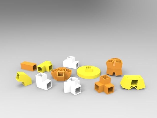 It seemed that in our era of digital technologies, when any scenes and fantastic attributes can be reproduced using computer graphics, the problems of filling any fantasy film with colorful spectacular details will become a thing of the past. However, screen masters have become convinced that not everything can be created with a graphic image, and therefore directors are still looking for ways to realistically convey the incredible appearance of the intended characters and create amazing objects of the fictional world. The graphics help to reproduce the overall environment in an incomparable way, but the human eye cannot be deceived and close-ups are often impossible to make believable using the style of a computer game. And then 3D printing came to the aid of directors and cameramen, thanks to the possibilities of which make-up artists and effects specialists today create unimaginable screen images.
Where and how did the 3D printer work?
A quarter of a century ago, it was hard to imagine that technological and scientific progress would so significantly change the technologies for preparing props for the film industry.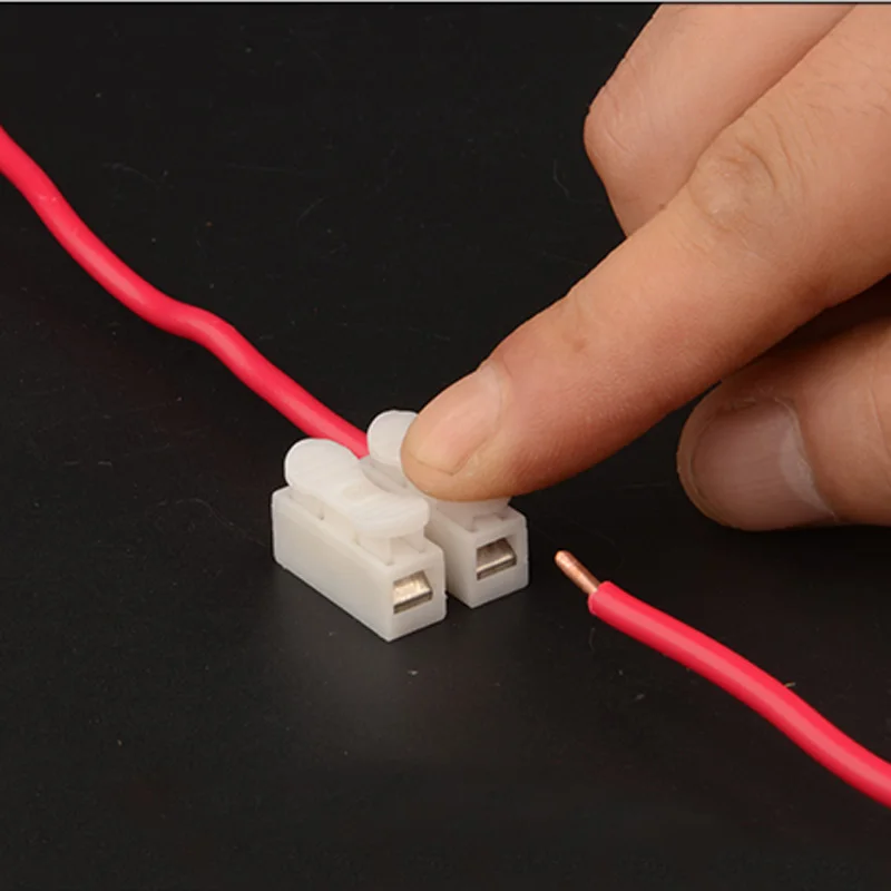 Even in such a cult film of 1997 as "Men in Black", which was replete with alien guests, the process of creating unprecedented characters consisted in hand-molding from clay, familiar to the "kitchen" of the cinema. Not a single worthwhile spectacular scenario could do without the work of experienced craftsmen. The manual production of unique layouts and details for effects was time consuming and costly. And at the same time, there were always risks that the created images would not be able to fully convey what was intended. But 3D printing has changed everything, without which it is now difficult to imagine the process of modern film production.
Fans of Stranger Things may not know that it was the 3D printer that was used to create objects for the scariest scenes. The task of the authors was to accurately reproduce the atmosphere of the 80s, and to achieve their goals, the creators used a kind of hybrid method, combining the possibilities of graphic editing and 3D printing. As a result, we can say that both technologies perfectly complement each other. From simple sketches of the monster, with which the authors turned to the special effects studio, the creators came to a realistic embodiment on the screen not only of the character himself, but also completely reproduced the whole bewitching inverted world. A striking example of technological interaction is the Demogorgon model, which was created by a 3D printer, but the mouth mucus appeared with the help of graphics, and the fire was brought up for real. As a result, the viewer is completely immersed in believable footage, and the series has been in the top of the best films since the first season.
New technologies could not ignore the mastodon of Hollywood fiction, the recognized master and creator of space worlds Ridley Scott. The 2020 series Raised by Wolves, produced by HBO Max, required the director to think outside the box when it comes to screening another sci-fi story in which androids are busy creating a new population of people on a desert planet.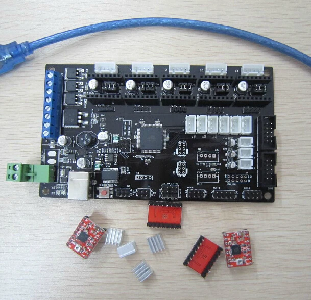 Almost all the components and elements of the new world were reproduced by 3D printing. It was only thanks to the technological acceleration of behind-the-scenes production of props and furnishings that the famous director's production team was able to keep up with the tight schedule of working in the challenging conditions of South Africa. Each episode took 2-3 weeks to prepare and film. During this time, sketches were prepared, layouts were designed, final details were agreed. Everything happened with the direct participation of the art director of the picture Yako Snaiman and Ridley Scott himself.
The most difficult thing was to create the main character of the film - android. This required a head scan of the actress. Next, a transparent polymer copy was printed through which the liquid could be seen. Metal parts were highlighted in chrome, and the containers were filled with water with a common food coloring that mimics yellow acid. Small details of the severed head, muscles, skull were created by the Zbrush program. Many elements were printed separately and assembled together. When installing the details on the actor's head, it was possible to achieve a real feeling that an artificially created person was in front of the audience. If not for the possibilities of 3D printing, no previous technical tricks and skill of design technicians would have allowed the series team to meet the allotted time and give the characters such a realistic look.
Most of all, the creators of the Marvel Universe know about the indispensability and practicality of 3D printers. Not a single studio film is complete today without the use of 3D printing technology. Only such fast and precise production is able to provide the film sets with the necessary props. Russell Bobbitt, who is in charge of this direction at Marvel Studios, says that everything that we see on the screen in the hands of the Avengers, on their costumes and in the setting, is created only through printer printing. Without it, such an unthinkable number of objects and details simply would not have been physically possible to recreate. Thor's hammer and Captain America's shield, Iron Man's reactors and hundreds of other elements of a fictional space future - all this became possible only thanks to the latest technologies. Russell remembers first encountering 3D printing on the set of Star Trek in 2009.1999, where director and producer J.J. Abrams introduced him to new technology.
The first 3D printer that Bobbitt himself used cost an insane $150,000. Today, these technologies have become much more accessible. And most importantly - cost-effective. At a time when the financial success of films and series has become directly dependent on the speed of the filming process, when it is necessary to shoot not just spectacular science fiction, but entire series of space battles and sci-fi everyday life in the shortest possible time, only 3D printing provides the film industry with the necessary amount of stage props. Professionals are delighted with the prospects that have opened up and understand that with all the development of computer graphics, the times of 3D printing are just beginning, and the viewer will see more and more incredible frames with real and live special effects.