3D printed case feeder
▷ hornady lock and load case feeder 3d models 【 STLFinder 】
Hornady Lock n load AP Case Feeder V2
thingiverse
Hello, Here are the files for the Hornady Lock n load AP Auto Progressive Press Case Feeder V2 In this version, the dove tails are removed and replaced by lap/dado type joints. Assembly now requires common #4x1/2 and 3/4 sheet metal screws and epoxy...
Hornady Lock n load AP Auto Progessive Press Case Feeder.
thingiverse
I use a bit stiffer spring in the turntable part, and tighten it far enough that rotation is just still barely possible so it doesn't flop around. ---------------------- This is a 3D printable case feeder for the Hornady Lock n load...
Hornady Lock n load AP Auto Progessive Press Case Feeder
thingiverse
I found by using a flat file and filing the slots, the "highspots are taken out and the parts slide easily. Then apply a light coating of moly grease and you should be all set. - Pattern and lower slide...(New see update 1/10/19) The lower slide...
Hornady Lock n load AP Case Feeder V2 - 5/8" Tube Holder
thingiverse
Remix part for Bartje64's printable case feeder V2 https://www. thingiverse.com/thing:3844226 The tubes I ordered from e-bay were 5/8" OD, 1/2" ID plexiglass. They were just a bit too wide to fit in the tube holder on the original, so I took it into...
Hornady Lock-N-Load AP Progressive Press Breakaway Primer Feeder
thingiverse
This is a breakaway replacement piece for hornady lock n load progressive reloading press. ... Print Settings Printer Brand: Prusa Printer: ...
Hornady Lock and Load Powder Measure Wall Mount
thingiverse
I made this to hold my Hornady Lock and Load powder measure. I wasn't able to find anything that I was really happy with so I made my own. I didn't want any extra things on this particular mount, I just wanted a secure place to be able to put my...
Jumbo Bin for Hornady Lock and Load Progressive Reloading Press
thingiverse
This is my Jumbo-sized catch bin for the Hornady Lock-and-Load Progressive press. It holds... well, quite a lot of fresh new ammo, compared to the stock Akro-Bin that comes with the press. The photos show 200 rounds of .40SW, and there's clearly room...
Hornady lock and load podwer check 3.0
thingiverse
I designed this powder check for my Hornady lock&load AP reloading press. If you have any questions please feel fee to ask. ...I believe I used a 1.5' long 6-32 pan head screw along with the powder stop.
Hornady Lock and Load powder check, Led Ring, switch box
thingiverse
Pulverstandsprüfer, Led Ring und eine Schalterbox für die Hornady Lock and Load 5 Stufen Presse. Für den Pulverstandsprüfer wird benötig:
https://www.grauwolf.net/hornady-powder-cop-pulver-fuellstand-ueberwachungsmatrize.html
3 rote...
Für den Pulverstandsprüfer wird benötig:
https://www.grauwolf.net/hornady-powder-cop-pulver-fuellstand-ueberwachungsmatrize.html
3 rote...
Hornady Case Feeder Wedge
thingiverse
This is a wedge to help keep cases from getting jammed in the case feeder (looking at you 9mm). install the wedge and if you need extra support drill and clamp it into position. Make sure its seated nicely with the tip flat. It keeps jams down by...
Hornady Case Feeder Tip
thingiverse
Hornady Case Feeder Tip Tube from: https://www.youtube.com/watch?v=_Ww0Snk6JlQ Have fun with it! . ..
***UPDATE 2018/03/27***
- bigger cutout
- new version without worm screw hole
***UPDATE 2018/03/02***
- added v2 version with thicker walls
..
***UPDATE 2018/03/27***
- bigger cutout
- new version without worm screw hole
***UPDATE 2018/03/02***
- added v2 version with thicker walls
Hornady Case Feeder
thingiverse
- V4 had mayor timing changes, is now EOL and replaced by V5 - V5 offers custom case selectors, custom fit lower slides and other features. Feel free to print V1 for a basic working case feeder. Otherwise go here for info on V5. ...
Hornady Case Feeder, Hornady Case Loader V4
thingiverse
If you're using V1, V2, V3 or V4 and have comments, questions, suggestions, look up the Facebook group "Hornady Case Loader V4" https://www. facebook.com/groups/1320385661631125 *********************************** Revisions and updates...
Hornady Lock-n-Load Tool Holder
thingiverse
This is a simple tool holder for my Hornady Lock-n-Load press. Its small enough to be out of the way and still be convenient. It has spots for four Allen keys and a brush. The four keys are: 5/16 - For the plate 5/32 - For the primer tube 1/8 - For...
Hornady Lock-n-Load Die Stand
thingiverse
... making adjustments, so they're not rolling around my workbench. ...This stand will hold 4 dies in their lock-n-load bushings, and can even hold the case activated powder measure. ...They simply drop in place and don't lock, so it's easy to remove them.
Hornady Lock-N-Load Overall Length Gage Modified Case 300 AAC Blackout, 300 Whisper
grabcad
To use the Lock-N-Load Overall Length Gage Hornady caliber-specific Overall Length Gages are required for use (sold separately). ...These Overall Length Gages are made for all common cases from the 17 Remington to the 500 Nitro Express and are oversized...
Hornady Lock n Load Primer catcher
thingiverse
This is a mountable primer catcher for the Hornady Lock n Load. Simply mount the primer catcher to the side of a desk and run a flexible tube from the primer discharge chute to the catcher. ...Will hold a few thousand primers before needing to be...
Hornady Lock-N-Load AP Large Bin
thingiverse
Large one part bin for the Hornady Lock-N-Load auto progressive press. This works great with my setup including the InLineFabrication mount for the press. This may or may-not work with different press mounting setups. This is much larger than the...
Hornady Lock-N-Load Reloading Die Holder
thingiverse
A very nice and neat way to store reloading dies in their Hornady Lock-N-Load bushings, the best QD way to use reloading dies. This holder will hold a total of 5 dies. It also has a slot to stand a powder scoop and a shelf for the shell holders.
I...
This holder will hold a total of 5 dies. It also has a slot to stand a powder scoop and a shelf for the shell holders.
I...
Hornady Lock-N-Load bullet tray
thingiverse
BTW, in some of my pictures you can see the excellent case feeder remix by bartje64 located here: https://www.thingiverse.com/thing:2883143 I have included the openSCAD files so you can edit things if you need to. I only ask that you give credit and...
Hornady Lock-n-Load Primer Alarm
thingiverse
This is modeled after the Hornady Lock-N-Load® Control Panel Primer Level Sensor. It slips over the primer tube and the clamping shaft collar from McMaster will activate a microswitch when the primers drop to a certain level. The hole at the...
Case flipper (.223/5.56) for Hornady Lock-n-Load Press for swaging
thingiverse
The case wheel is a friction fit on the motor coupling incase if jamming. ... YouTube video - https://youtu.be/UFJEm6fwK6M Parts used, Motor - https://www.amazon.com/gp/product/B07FD98N8J/ref=ppx_yo_dt_b_asin_title_o05_s00?ie=UTF8&psc=1 Motor...
Hornady Lock 'n Load Powder Measure Stand
thingiverse
... Measures (incl. case activated powder drop) to install directly on the bench when they are not in use on the press. The small holes are only to safe filament and print time.
This is my first try with CAD so it's not perfect, but it works. ...;-)
The small holes are only to safe filament and print time.
This is my first try with CAD so it's not perfect, but it works. ...;-)
Hornady Lock-N-Load Bullet Tray
thingiverse
2/13/21 Added Ex Large bullet tray and added a drop down dovetail for the screw type clamps. Also added 2 new clamp designs to accommodate some newer presses with the ridge that runs along the back. This relief cut might also allow room to install...
Hornady Lock N Load Primer catcher
grabcad
Mount under your press and use the vinyl tube supplied with your press. ...Just run the tube from the discharge chute to the catcher.
Auto feeder for Hornady case feeder
thingiverse
This is an auto case feeder for the Hornady lock and load case feeder. This eliminates the feeding tubes. ... You need motor to drive the case feeder relay micro switch 12m proximity sensor no or nc will work 12v power for motor I also made a new pick...
Hornady Case Feeder Tube Adapter
thingiverse
For those that have printed the Hornady LNL case feeder (https://www.thingiverse.com/thing:3844226) and are looking for a way to hook up a case collator, This is a your solution. This will accept the Dillon case feed adapters for you to easily adapt.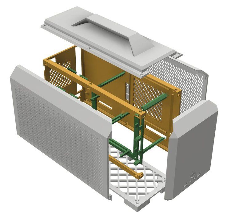 ..
..
Hornady Case Feeder Tip (remix)
thingiverse
The walls of the original were too thick to fit between the tube and the body of the press. This version has a thinned section nearest the press to add clearance. ... I also added a split section that can be tightened with a 3mm nut and cap-head bolt.
Lock and load die holder
thingiverse
I wanted to organize my dies that had the Hornady lock and load setup on them on my wall, so I created this quick holder. its my first creation so be gentle... ...lol
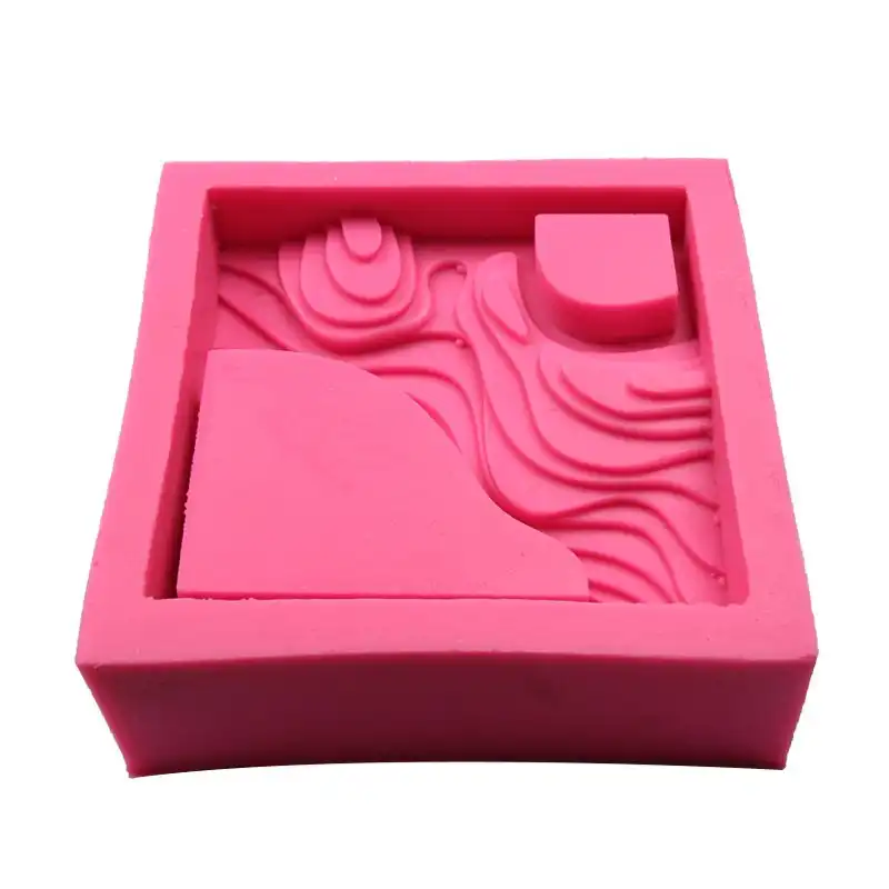
Universal Case Feeder Set for Lee Pro 1000 Loadmaster and APP
This is a custom designed replacement case feeder set for Lee Pro 1000 and APP reloaders. Simply replace the stock bottom end tube holder and metal spout with the adapters and then insert your caliber spout. The tube holder contains ball spring plungers and is locked in place when rotating by detents in the bottom plate. The caliber spouts are held in place by pins. All hardware is included with the adapters (already assembled), caliber spouts include only the printed part.
From the drop down menu you can chose if you want only the adapters or the adapters with 1, 3, 5, 10, or all 16 calibers. We also have the caliber spouts by themselves if you need more later. The choices of caliber are below. These are the only calibers we have at this time and these are the only ones we can confirm fit and work. If in the future we are able to test other calibers, we will provide them but ONLY if it is caliber we are able to test ourselves to confirm it works.
6.8 spc Brown
9mm Red
30 Light Blue
32 long Purple
32 Magenta
38 spc Crystal Black
40 Gold
40-44 Crystal White
44 Yellow
45 Orange
223 Blue
224 Pink
357 SIG Crystal Red
357 Lime Green
380 Green
454 Mint
Please note: the above calibers are for what they say they are. Do not assume they will work for anything else. For example, the 45 spout is for 45 and NOT 45 colt, there is a size difference and we do not have the 45 colt. This is the same for all calibers. If you are unsure, please ask before purchase. If you request calibers we do not offer in your order, we will include the closest thing we do have. I put this note here because too often we get orders that include requests for calibers we do not offer and we simply do not have the time to explain to each person that they chose one we do not offer.
If you choose the adapters with caliber spouts, be sure to tell us in the personalization field what calibers you want. If left blank we will pick at random and nobody wants that. If you choose adapters with 3 calibers and then list 5 calibers in the personalization field, we will include the first 3 ONLY, so be sure you choose the correct number of calibers you want.
To keep it simple and keep the calibers easy for you to tell apart, we are making these all the same color scheme. Adapters are black and the caliber spouts are the colors listed above as seen in the pictures.
IMPORTANT NOTE!
This set was redesigned using another model as a base but was significantly modified to fit both the Pro 1000 and the APP reloaders. All of the hardware holes were changed to fit better with the included hardware. If you purchased the set we used to sell, THESE PARTS WILL NOT FIT THOSE.
Our typical turnaround is usually about a week depending on how many open orders we have at the time. IF YOU NEED YOUR ORDER BY A SPECIFIC DATE, MESSAGE US FIRST! Everything we sell is custom made to order.
Check out our shop and see all the personalized items we have... if you have a custom order request, please message us! We can make almost anything 3D Printed or with vinyl. Shipping is a flat rate no matter how many different items you get from our shop! If you spend $35 shipping is FREE!
Please "like" our facebook page: Facebook.com/ChalmationCreations or check out our website, ChalmationCreations.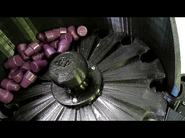 com!
com!
Because of the way 3d printing works, not often but sometimes there can be burn marks or other imperfections in printed items. While we do our best to avoid these, some are unavoidable. As long as they are relatively small and not on a side or edge that is showing during normal use or do not detract from the overall appearance we consider these to be acceptable.
3D Printing Caliper Structures - Complete Guide
An Easier Approach to Caliper Structures
Caliper Structures for 3D Printing - The Complete Guide
Everything you need to know about caliper structures used in 3D printing. Feel free to use overhangs and bridges in your models!
Caliper structures: If you have a lot of experience with FDM 3D printing (FDM - deposition layer modeling), you may have found yourself in situations a couple of times in which you had to use such structures. An FDM 3D printer creates a 3D object by sequentially applying layers of thermoplastic materials. In this case, each new layer rests on the layer below it. If the model has an overhang that is not supported from below, it will likely sink or even fall off, and you will need to print additional support structures to ensure successful printing. nine0004
Caliper structures are seen as a necessary evil in 3D printing. On the one hand, they are absolutely necessary for models with dangerous overhangs or bridges. On the other hand, the cost of materials rises, finishing work is added, and there is a risk of damage to the surface of the model. Therefore, proper application of printed caliper structures is a very important aspect of 3D printing complex models.
Caliper structures in 3D printing: 3 easy steps to success
In this article, we will cover everything you need to know about support structures used in 3D printing. Detailed explanations are provided later in the text.
WHEN DO YOU NEED THEM?
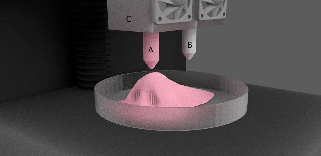
In general, when a model has an unsupported overhang or bridge, caliper structures may be required to enable 3D printing. The figure below shows overhangs and bridges using the letters Y, H and T.
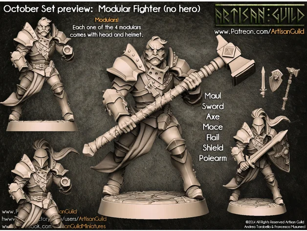
A classic example of overhangs and bridges using the letters Y, H and T.
Support structures are not required for all overhangs - 45 degree rule
Support structures are not required for all overhangs. As a general rule of thumb, if the overhang slopes less than 45 degrees from vertical, it can be printed without the use of caliper structures.
Support structures are required for overhangs greater than 45 degrees from vertical.
3D printers provide a slight (barely noticeable) horizontal displacement between successive layers, i.e., the applied layer is placed on the previous one with a slight displacement. This ensures that overhangs are printed that do not deviate too much from the vertical. Anything less than 45 degrees can be supported by previous layers, and anything above that number can't. A value of forty-five degrees is considered a break line. nine0004
This statement is best supported by the examples of the letters Y and T. The two slanted parts of the letter Y have an angle of less than 45 degrees with respect to the vertical. Therefore, if necessary, the letter Y can be printed without the use of any caliper structures performed by 3D printing.
For overhangs in the letter Y, printing of support structures is not required. But for overhangs in the letter T - yes. (source: 3DHubs online production platform)
On the other hand, the protruding parts of the T are at an angle of 90 degrees from vertical. Thus, in this case, for the 3D printing of the letter T, the use of support structures is a necessary condition, otherwise the result will be a nightmare (see the figure below).
Without caliper structures, it is not possible to properly print the letter T (source: 3DHubs online manufacturing platform)
2
Not all bridges need supports - the 5 mm rule.
As with overhangs, supports are not required for all bridges. A rule of thumb that has been proven in practice is that if the bridge length is less than 5 mm, the printer is able to print it without the need for a caliper structure. nine0004
This uses the 'bridging' printing method, in which the printer stretches the hot material over short distances and prints it with minimal sag.
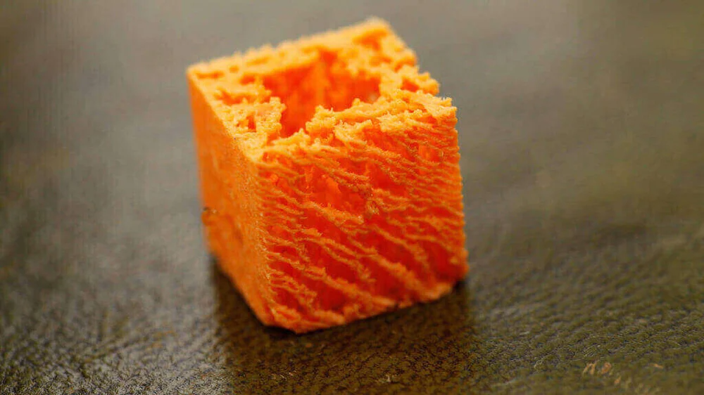
However, if the bridge length is greater than 5 mm, this method does not work. In this case, it is necessary to additionally print support structures.
Bridges longer than 5 mm cannot be printed without support structures. Notice how they warp and deform.
TESTING PRINTER'S ABILITY TO PRINT OVERHEADS WITHOUT SUPPORT
The rule of thumb that if an overhang slopes less than 45 degrees from vertical, it can be printed without the use of support structures is just a rule of thumb. Much depends on the printer, its condition and the materials used. Printers that are in poor condition may not print 35 or 40 degree overhangs from vertical.
Before printing a model with overhangs, it is recommended that you evaluate the printer's ability to print small overhangs. nine0004
This is easy to do. Simply download the Massive Overhang Test print model from the Thingiverse website and print it. This model presents overhangs from 20 to 70 degrees in 5-degree increments.
Overhang print test model from Thingiverse website (source: Thingiverse website)
Determine the angle at which the printer starts to print abnormally. This is the maximum overhang angle at which the printer can print without support. It is recommended to remember it for making further decisions on the need to use support structures. nine0004
DISADVANTAGES
Like many things in life, the use of support structures in 3D printing has certain weaknesses. There are several of them, so let's look at them.
1
Increased material costs
Support structures require additional materials. In this case, these designs after printing must be removed and thrown into waste.
When using 3D printing at the manufacturing level, the focus may be on model costs. If this is your hobby and you are limited in funds, then, for sure, this is also not indifferent to you. nine0004
3D printing of support structures means an obvious additional cost per model. Caliper structures require material that is subsequently removed and discarded, so any 3D caliper structures go to waste, which increases the cost of the printed product.
2
Print time increase
3D printing of support structures also increases print time as the printer prints additional volumes. It is quite obvious that the additional time spent depends on the number and height of the support structures. nine0004
3
Additional finishing
Additional finishing is required when printing support structures. (source: Formlabs)
3D printed support structures are not part of the model. They are used as a support for parts of the model during printing. This means that at the end of printing, there is an additional need to remove these structures before the model is ready for use.
In a production setting, extra work means additional costs for the model.
4
Risk of product damage
Left: Printing with supports. Middle: Removal of calipers with product damage. Right: Removal of calipers without significant damage to the product. (source: 3DHubs online manufacturing platform)
3D caliper structures come into contact with the walls of products and often stick to them. They are the only means of providing support under overhangs and bridges. If care is not taken when removing 3D caliper structures, defects may remain on the surface of the product. In the worst case, part of the model may break off along with the 3D support structure. nine0004
In general, there are significant drawbacks when using support structures.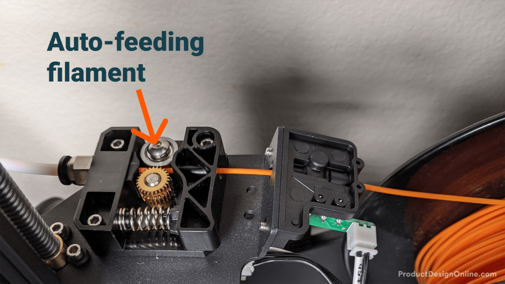 Therefore, here is another tried and tested rule: minimize the use of 3D support structures and add them only when necessary . The following sections will explore the application of this principle, starting directly from the computer-aided design (CAD) stage and ending with printing.
GEOMETRY OF THE CALIPER STRUCTURE
Two types of support structures are commonly used: tree-like ("tree") and linear/"accordion". nine0004
Tree calipers
The tree caliper is a tree structure that serves as a support for the overhangs of the model. Calipers of this type only come into contact with the overhang at certain points.
3D tree supports (source: Flashforge)
The advantage of using a 3D tree support is that it can be removed more easily without significant damage to the underside of the overhang. However, it should be noted that this type of caliper is only suitable for non-flat overhangs, such as the tip of the nose, toe or arch. For flat overhangs, it does not provide sufficient stability. nine0004
Linear support or "accordion"
This is the type of support most commonly used in 3D printing. It consists of vertical posts that are in contact with the overhang over the entire surface. This type of caliper is suitable for any overhangs and bridges. However, it is more difficult to remove without damaging the surface of the model.
Linear 3D support structures (source: Flashforge)0007
Tear-off 3D support structures
Single-extruder printers use tear-off support structures by default.
If you have one extruder, you have to use the same material to 3D print the support structures that is used to print the model. Of course, the density of the caliper structures can be adjusted to be much lower than the density of the model, but this is the only remedy that can be applied to the material of the caliper.
Since the model and 3D caliper structures are made from the same material, the only way to separate them is to either break off the caliper by hand or carefully cut it off with a knife.
These removal methods carry a high risk of damage to the model, and during removal, you must use the proper methods and be extremely vigilant and careful.
2
Dissolvable 3D calipers
Dissolvable calipers are easier to remove, but requires a printer with two extruders. nine0004
If you have a dual extruder printer, you have a better choice. You can load one extruder with PLA for model printing and the other with water soluble material such as PVA or limonene soluble material such as HIPS (polystyrene) for caliper structure printing. At the end of printing, it is enough to simply remove the support structure by washing off by immersing the model in water or limonene.
This removal method reduces the risk of model damage and simplifies finishing, making it ideal for complex prints. nine0004
HOW TO REMOVE 3D SUPPORT STRUCTURES
Because 3D caliper structures are difficult to remove and can damage the model, here are some tried and tested techniques for removing them properly.
- First you need to determine which support structures are completely open and can be easily reached with your fingers. Try prying these calipers off with your fingers. Exercise caution. Extreme caution. If this operation is performed correctly, most caliper structures should come off without much effort. nine0209
- Then take a tool to remove 3D support structures that are difficult to reach. There are many opinions about which tools are best. You can use needle-nose pliers, a spatula, or a utility knife. You can also use all these tools together.
- When using a knife or scraper, it is a good idea to heat up the model or blade. This contributes to better delamination of the 3D support structures. A small butane torch will help, but care must be taken not to damage the model. nine0209
- Handle utility knives with care as they are very sharp.
- Sandpaper is also excellent for removal. When wet grinding with fine-grained sandpaper (from 220 to 1200), not only the removal of 3D caliper structures is performed, but also the model is polished.
 For best results, it is recommended to spray the part with water and sand with smooth, light movements until the desired surface quality is obtained.
Wet sanding can be used to remove residual 3D caliper structures and smooth the surface of the model (Source: Formlabs) scratches and surface defects. Nail polish is great for partially or completely covering these marks.
If you are interested in how other users solve this problem, it is recommended that you view the web page on the best ways to remove supports, calipers and filament structures - Best ways to remove foundations, caliper structures and other external filaments. nine0004
MINIMIZING 3D CALIPER STRUCTURES WITH SMART DESIGN
Integrating 3D caliper structures into the model
One way to avoid the use of caliper structures in 3D printing is to use additional elements in the model that perform a similar function. Sculptors have been using this technique for centuries. As an example, consider the sculpture "Venus the Conqueror" by Antonio Canova.
"Venus the Conqueror", sculptor Antonio Canova
Here the right arm is an overhang but rests on pillows. The left leg is another overhang, but here the folds of the toga serve as a support.
The next example is the Guardian model by @fantasygraph. As a support for the legs and buttocks of the model, he guessed to use a dress flowing in folds. The left hand rests on the spear lowered down.
The Guardian by @fantasygraph is a prime example of how support structures can be integrated into a model. nine0004
Integrating 3D support structures into a design is more art than science. It is necessary to find such elements that fit into the overall design and at the same time can be a support for overhangs or bridges. When done correctly, the model will be more beautiful and the printing process will be free from unnecessary 3D caliper structures, which means saving time, money and labor.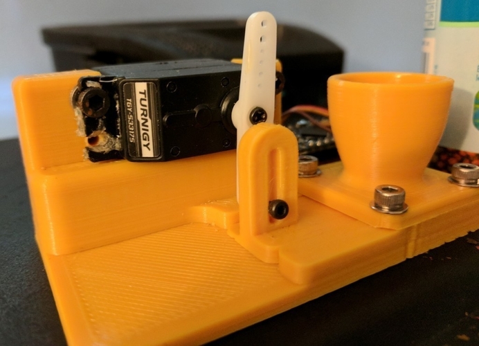
Bevels
Another way to get rid of 3D support structures is to use bevels. With proper chamfering, dangerous overhangs can be turned into harmless structures with angles less than 45 degrees. nine0004
For example, if you have a smoothly falling or folded edge, you can replace it with an edge with an angle that does not require supports. Such an angular pattern is called a bevel.
Left: Gradually rounded edge that requires supports. Right: A beveled edge that can be printed without 3D caliper structures (Source: Rigid Ink)
Similarly, if your model has a hole, you can turn it into a bevelled teardrop hole. For the most part, this won't ruin the overall aesthetic of the model, but will help reduce the amount of 3D support structures needed to print the model. nine0004
Beveled hole (source: Markforged)
MINIMIZING 3D SUPPORT STRUCTURES BY REORIENTATION
. For example, it is much better to print the open box shown below with the open side up.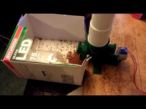
You can often minimize the use of 3D support structures by properly positioning the model on the build plate (Source: Markforged)
Below is a more non-trivial example, again from designer @fantasygraph. This is a model of a man with a horizontally outstretched arm pointing forward and to infinity.
If you print the model as is, you will need to support the left hand. And it, in fact, is a long overhang with an angle of 90 degrees.
Removing the supports will most likely leave imperfections on the underside of the arm. To avoid this, you can rotate the whole model by 45 degrees and simply add a support for its base. In any case, the quality of the basis of the model does not really matter. Thus, it is possible to print a model with fewer 3D caliper structures and save the left hand from damage. nine0004
A simple and ingenious solution. Maybe you can do it too?
PRINTING OVERHEADS AND BRIDGES WITHOUT 3D SUPPORT STRUCTURES
In the previous sections, attention was drawn to the fact that, if possible, you should try to use as little 3D support structures as possible.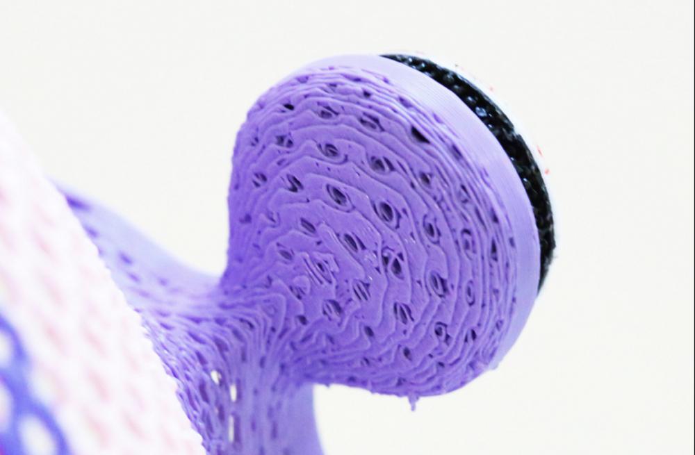 However, this means that it will often be possible to find yourself in a difficult situation in which the risk of model instability is inevitable. To minimize these risks, here are a few general tips. nine0004
- Make sure the 3D printer is in optimal condition.
- Cool the printed material as quickly as possible. The longer the material cools, the more likely it is that the bridge or overhang will warp or fall off. To do this, it is necessary to maximize the cooling capacity of the layers by cooling fans. Also, reduce the print temperature to the lowest possible.
- Reducing the print speed also speeds up cooling and is especially helpful when printing longer bridges and complex overhangs. nine0209
- It is recommended to print with the minimum layer thickness. Less layer thickness means less weight applied with each pass of the print head. In addition, it contributes to faster cooling of the material.
SUPPORT STRUCTURE SETTINGS IN CURA
Sometimes 3D support structures are simply indispensable. But even in this case, every effort must be made to ensure the stability of the 3D support structures, so that they do not consume a lot of material, they are easily removed and do not damage the surface of the model. nine0004
The layering manager has many additional functions for fine tuning support structures. Most layering programs can automatically create calipers, but they also have a manual mode that lets you add or remove calipers anywhere. In addition, the layering manager has many different settings to control the following aspects of the caliper structures.
- Location of 3D supports
- Strength of 3D supports
- Easy removal after printing
- Damage to the printed surface
In this article, we decided to focus on Cura, one of the most popular free layering software.
Cura has a number of settings related to support structures located in the Support section of the Custom Settings menu. With the right settings for these settings, you can create 3D support structures that meet most basic requirements.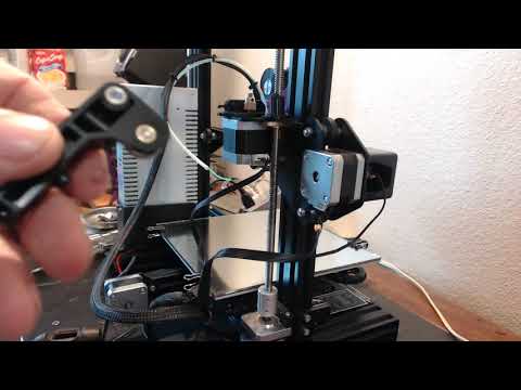 nine0004
1
Enable automatic creation of 3D support structures for unstable models
Let's start from the beginning. How can I check if a model needs additional supports?
Cura makes this easy. Immediately after importing the model into Cura and placing it on the virtual working base, you should pay attention to the areas colored in red. These are the areas where Cura found instability. It should be noted that, possibly, areas without supports will not be visible until the camera is rotated. nine0004
If the bottom of the part is painted red where the model touches the work base, don't worry that there is no support underneath. This problem will be solved by a working base. Small red areas at the top of holes or between two structures are called bridges and Cura will process them automatically.
You should start to worry if there are other parts highlighted in red. First you need to activate the automatic creation of support structures in order to ensure that these red areas are successfully printed. To do this, just check the Generate Support checkbox in the Support section. nine0004
So, the function of automatic creation of support structures is activated, but no external changes to the model occur. The reason is that Cura does not show support structures in the default Solid view. To view the generated 3D support structures, you must change the view mode to Layer View (View layers). The material of the calipers (lines and volume) will be displayed in turquoise. You need to move the layer slider up and down to see where the support is added to the model. nine0004
2
Selecting a tree or linear support
Tree support structures in Cura
Cura creates 3D linear support structures by default. Version 3.2 beta of Cura provides the option to use tree supports instead of the default linear ones.
3
3D Support Structure Position Control
Two types of support structure positioning in Cura: Everywhere and Touching Build plate
When you activate the option to create support structures, the Placement item automatically appears in the Support section. The Placement option provides the ability to control the approximate location of support structures. There are two options: Everywhere and Touching Build plate. The Everywhere option is selected by default.
When the Everywhere option is selected, Cura 3D attempts to create support structures where they are needed. This means that not only 3D caliper structures will be created that will be placed on the working base, but also caliper structures that will be based on the details of the model. This is the rational choice for most cases, as it guarantees the necessary support for all unstable areas. nine0004
However, if you select the Everywhere option for very complex models, the model may be completely covered with the material used for the calipers. If there is no such intention, you just need to set the Touching Build plate option in the Placement settings. This option will create 3D caliper structures under the hanging parts of the model only between the working base and the model.
4
The Enable Support Roof option can improve the surface finish of overhangs, but will incur some additional cost. nine0026
Since the overhang of the model is always printed on top of the 3D support structures, the optimal surface finish of the parts is not always guaranteed. And in this case, the hidden setting Enable Support Roof can help.
The arch of the support is a dense layer in the upper part of the caliper structure, which does not degrade the surface quality of the overhangs too much. When this option is activated in the Cura 3D program, by checking the appropriate box, a better quality finish is obtained. But this improvement comes at a cost, as removing the caliper structures becomes more difficult than usual when choosing this option. This option is only recommended if the surface quality of the overhang is important to the finished part itself. nine0004
5
Prevent 3D support structures from damaging the outer walls of the model by using the Support X/Y Distance setting
Sometimes 3D support structures are too close to the outer wall and leave traces on the outer surface of the model. This can be avoided by using the hidden Support X/Y Distance setting in the Support section.
In Cura, the Support X/Y Distance setting generally controls the minimum allowable distance between the model's vertical walls and the support structure in the X-Y plane. If the 3D support structure damages or sticks to the walls, you can increase this value in 0.2 mm increments until the walls are smooth. However, it is highly recommended to ensure that there are no small overhangs protruding from the outer walls, which would be left unsupported by leaving a small distance between the support and the walls. With these small overhangs, you may even need to decrease the X/Y distance instead of increasing it. Otherwise, printing will fail. nine0004
6
Z Distance setting to allow for easier removal of 3D support structures model layers. The Cura software creates this weaker connection by leaving a certain space between the top and bottom of the support structure and the model - this space is known as the Z distance.
By setting the hidden Z-Distance settings in the Support section, the 3D support structures can be more easily separated from the model. The default value of this setting is equal to the height of the layer. So if the layer height is 0.1mm, the default Z distance will also be 0.1mm.
If the support material is difficult to separate from the model, it is recommended to increase this value in increments of layer height until it separates cleanly. Cura may or may not provide additional support for any particular layer. Unfortunately, half layer values do not exist. That is, if the Z Distance value of 0.2 mm is too large for printing with a layer height of 0.1 mm, and the Z-Distance value of 0.1 mm is not enough, there are no other options for setting the Z Distance value. nine0004
7
Choosing the right 3D caliper structure to strike the right balance between strength and ease of removal
Support patterns in Cura
Cura provides one of seven 3D caliper patterns. The pattern can be changed using a hidden setting called Support Pattern in the Setting section.
In most cases, the default pattern, Zig Zag, provides the best balance between strength and ease of removal. Other scheme options: Triangles (Triangles), Lines (Lines), Grid (Lattice), Concentric (Concentric), Concentric 3D (Concentric 3D) and Cross (Cross). If the default schema doesn't work, you can experiment with other options. Each provides a different balance between strength and ease of removal. nine0004
Caliper structures are a necessary evil in 3D printing. They are needed to print complex overhangs and bridges on the model. But when soluble 3D support structures cannot be used, it is recommended to try to minimize their use. We've covered situations where 3D caliper structures aren't needed and mentioned a few creative tricks for printing without them.
However, often the overhang or bridge may be such that a support structure has to be used. In this case, you need to change the layering settings so as not to waste too much material and not damage the model during the removal of supports. Options for choosing the proper printer settings for optimal results were discussed, as well as some techniques for correct removal of 3D support structures. nine0004
We hope this article will help you improve your 3D printing results and the quality of your printed models. If you liked our article, please share it with your friends and colleagues in the field of 3D printing.
Share article:
Beginner's Tips for Getting Started with a 3D Printer, Table Calibration and Slicer Setup
Despite the abundance of videos and articles, the information in them is scattered and it can be difficult for a novice 3D maker to understand such an abundance of facts. In fact, everything is not so difficult, at the first stages it is enough to deal with just a few important nuances. nine0004
First use
Before using the printer for the first time, it is best to read the instructions. Each printer may have its own usage and settings. Some 3D printers are able to calibrate automatically, without user intervention, and some need to be configured manually.
If there was no paper instruction in the box, you can download it from the manufacturer's website. Some manufacturers stick a sticker on the box with a link to the current version of the instructions. nine0004
Before the first run, make sure all shipping locks are removed from the 3D printer. You can gently try to move the extruder along the axes with your hands to make sure that nothing interferes with its free movement.
Table calibration
The result of the entire operation of the printer depends on the calibration of the table. It is very disappointing to see that the model, after many hours of printing, came off the surface of the table and deformed or “moved out”. In order to prevent this from happening, it is necessary to correctly set the working plane and the gap between the table and the nozzle. nine0004
In many printers, manufacturers began to add an automatic print surface calibration sensor.
A special sensor measures the distance from the table to the nozzle and makes a “map” of irregularities that are taken into account when printing.
Table auto-calibration sensor
There is a semi-automatic calibration. In this case, the printer, using a sensor, determines the distance to the table and tells you which way to turn the adjusting screw. nine0004
Here we will look at the manual calibration of the working surface of the most popular mechanics of FDM printers - Prusa, H-BOT, CoreXY, etc.
Table leveling
First you need to level the plane of the table. To do this, using the adjusting bolts, it is necessary to set the same distance between the table and the nozzle. Anything can be used as a probe, but it is better to take the probe recommended by the manufacturer (usually 0.1mm). nine0004
Table calibration
-
Heat up the table.
 The 3D printer table is made of a metal plate, when heated, the metal expands, so it is better to heat the table before calibrating.
 -
Tighten the calibration screws as far as possible at the bottom of the print surface. This will help prevent the work surface from colliding with the nozzle in the next step. nine0004
-
Send table and extruder to zero position. Raise the table as high as possible or lower the extruder as far as possible with Prusa kinematics. This can be done from the menu with the HOME command. Make sure that the nozzle does not “crash” into the work surface.
-
Using the menu, move the nozzle so that it is above the calibration screw.
-
Place the probe between the work surface and the nozzle, use the screw to raise or lower the work surface so that the probe is firmly clamped. Repeat this for all table gauge bolts. There may be 3 or 4 of them. nine0004
-
Move the extruder to the center of the table and use a feeler gauge to check the gap between the table and the nozzle.
 If the gap is the same as above the calibration bolts, then the plane is aligned correctly, if the gap is different, then it is worth repeating the calibration or checking the flatness of the printed surface.
The square test can be used to check the uniformity of the table plane calibration.
nine0455
Work surface flatness test
Depending on the size of the work surface, you can place test squares in different places.
Test squares on the printed surface 30x30 cm
For this test, you need to print several thin squares (1 layer thick) on the printed surface. Depending on how they are printed, you can see if the table plane is evenly calibrated. nine0004
Table for determining the correct calibration of the table and nozzle.
Sometimes the printed surface is a bit uneven on its own and there are some small depressions or bumps in some places.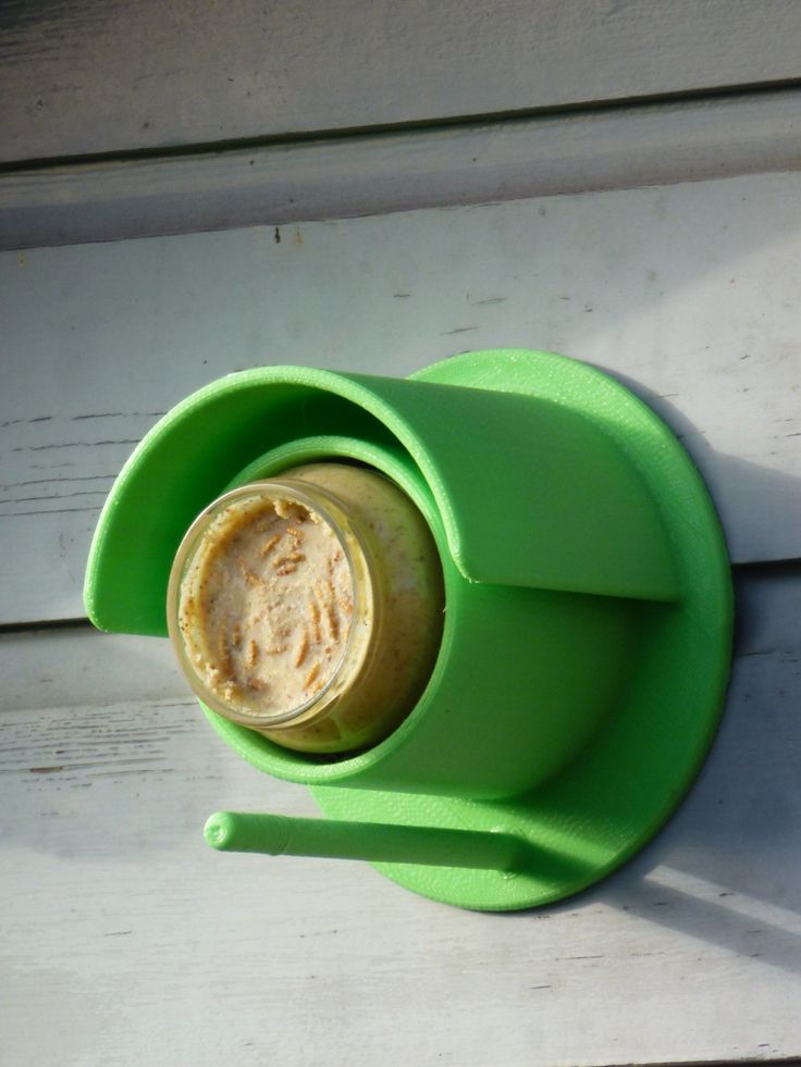 If it is not possible to change the working surface or there is no time to re-calibrate, you can try to print the model on the “raft”.
The raft is a thick substrate that is printed under the model. A thicker layer of plastic adheres better to the printed surface and “smoothes out” its bumps. nine0004
3D model printed on raft
Table to nozzle gap calibration
If a feeler gauge was used to align the work plane, which matches the required gap between the table and the nozzle, then the extruder does not need to be calibrated separately. If the printer has 2 extruders, then only the second extruder needs to be calibrated.
Some 3D printers, like the Raise 3D, come from the factory with a leveled bed, but it's a good idea to check the gap between the bed and the nozzle before printing. Settings may change during shipping. nine0443
Using the menu, you need to send the table and extruder to the zero position (HOME).
Using a feeler gauge, set the distance between the working surface and the nozzle recommended by the manufacturer (usually 0.1 mm). Some manufacturers recommend calibrating the nozzle “to the table” without clearance. The distance between the nozzle and the working surface can be adjusted by the calibration screw, which is located at the z-axis limit switch, programmatically or by the extruder. nine0004
If the printer has 2 extruders, then the calibration must be repeated with the second extruder.
After changing the nozzle, thermal barrier, table surface or moving the printer - it is necessary to check the gap calibration between the work surface and the nozzle, and sometimes the plane of the table.
Loading filament
After setting up the print platform, you can load the filament (plastic). nine0004
In some 3D printers, the plastic loading process is automated and starts from the menu.
It is necessary to heat the extruder to the melting temperature of the plastic filament.
The temperature range is usually marked on the box or spool of plastic.
After heating the extruder to a predetermined temperature, depress the lever that presses the filament in the feeder and push the plastic into the extruder until it starts to flow from the nozzle. nine0004
If necessary, fix the pressure lever so that it firmly presses the filament against the feed gear. (If the lever is not spring-loaded and does not return to its original position).
After loading the filament, you need to push the plastic bar a little until the remnants of the old plastic come out of the nozzle.
Setting print options
In order to get a neat and accurate model of the insufficiently good mechanics of a 3D printer, it is important to properly prepare the model using a special slicer program. nine0004
Table and nozzle temperature
Perhaps the two most important parameters are the temperature of the nozzle and the working surface.
These settings may affect other slicer settings.
Slicer CURA
Table temperature settings
A heated work surface is necessary for better adhesion of plastics with a high percentage of shrinkage, otherwise the part will simply come off the printed surface during printing. But due to too high a temperature, the lower layers can soften and deform under the weight of the growing model. nine0004
Depending on the surface of the table, the recommended temperature may vary. For example, if ABS is printed on a special substrate, the recommended table temperature is 100 degrees, and if glass with stationery glue is used as the work surface, the temperature should not be raised above 80 degrees.
Some manufacturers indicate the recommended table temperature on the box or on their website. But there are general temperature ranges that you can focus on. nine0004
PLA - 0 - 50 degrees.
During printing, the plastic must be blown.
ABS - 80 - 90 degrees. Drafts should be avoided during printing.
Nylon - 80 - 90 degrees. Drafts should be avoided during printing.
Flex - 80 - 90 degrees. Drafts should be avoided during printing. nine0004
Nozzle temperature settings
The required temperature range is indicated by the manufacturer on the filament spool, but it is better to print a couple of small tests to determine the ideal temperature for a given filament.
After changing the nozzle to a nozzle with a different diameter or a significant increase in printing speed, it is necessary to slightly increase the temperature of the extruder. Due to the small “melt chamber”, the plastic may not have time to warm up to the desired temperature. nine0004
There are extruders with a large volume of "melting chamber" of plastic, but they are not suitable for every 3D printer and are designed to work with large diameter nozzles.
Conventional heating block and Vulcano block with enlarged “melting chamber”
Printed tests
To configure some slicer parameters, it is convenient to use special tests, rather than setting the settings at random. Some of the tests can be printed every time you change the spool of filament. For example, plastic from the same manufacturer, but with a different dye, may have slightly different temperature settings. nine0004
XYZ Cube
Printed Cube
This is one of the most popular tests that can be used to evaluate the quality of the surface and the accuracy of the kinematics of a 3D printer (belt tension, number of steps per mm, etc.). You can download it here
Boat 3D Benchy
A small test boat that allows you to evaluate many 3D printer parameters and slicer settings. 3DBenchy has become so popular that enthusiasts have come up with various fun and practical accessories for it.
nine0004
Parameters to pay attention to in the finished model
For two extruder printers, there is a boat that needs to be printed in two colors. You can download the model or find models of accessories for the finished boat here.
Boat for two-color printing
Simple temperature tower
Setting the correct print temperature is one of the most important factors in obtaining a strong model with a quality surface. Many factors can affect the fusibility of a plastic - the quality of the raw material, the addition of dyes, the speed of printing, the thickness of the layer, etc.
In order to understand how plastic behaves at different temperatures, enthusiasts came up with a simple test turret that prints at different temperatures at different heights. There are several types of these tests. Some have overhanging elements and “bridges”. You can download the test here.
nine0004
Temperature tower with bridges and overhangs
Turrets
Retract Turrets
These small turrets allow you to fine-tune the retract in your slicer settings. Due to their small size, they print very quickly. You can download the model here.
Bridge Print Test
Test Bridge
Some overhanging elements can be printed without supports, the slicer even has special settings for printing such “bridges”. To find the optimal parameters, you can use this small test model.
Surface overhang
nine0458 Test model
A small test that allows you to understand how the plastic will behave when printing overhanging elements. With this test, you can configure support settings in the slicer. You can download the model here.
Test All-in-one
There are printed tests - all in one, but it can be difficult for a beginner to figure out which settings need to be adjusted.
Therefore, to begin with, it is better to print simple tests, and with experience, you can use universal ones. nine0004
Printed test all in one
Model can be downloaded here
Common errors
Poor first coat adhesion
This is usually due to incorrect print surface calibration or insufficient adhesion of the first layer.
First you need to check the correct gap between the table and the nozzle. If necessary, calibrate the plane of the printed surface and the gap between the working surface and the nozzle. nine0004
To increase adhesion, you can use special adhesives that are applied to the printed surface. Check the correct temperature of the extruder, table and thickness of the first layer in the slicer settings. The higher the temperature of the extruder, the better the adhesion. The first layer is usually thicker than subsequent ones, because the thicker layer of plastic adheres better to the work surface.
Printer does not extrude plastic
If the printer stops extruding plastic and the feed mechanism starts to click, then most likely the problem is a clogged nozzle. The nozzle can be burned or cleaned, but in 3D printing nozzles are consumables and it is better to replace it immediately. nine0004
Plastic bubbles when printed
If the plastic bubbles when exiting the nozzle, then it must be dried. Some engineering plastics, such as nylon, need to be dried before each print.
Model is printed with errors
The slicer cannot always process the model correctly if it has errors. For example, inverted normals, internal walls, or the model is not closed. Such models need to be “cured” before printing. nine0004
Model printed with error
Some slicers are able to fix simple errors on their own, but if the slicer is powerless, you can use special programs designed to work with STL files.
Learn more