3D print moving parts
How to 3D Print Moving Components in One Print Job
3D printing fully assembled, multi-component parts in a single job allows you to see dynamic components working in their prototyping stages. Rather than 3D printing smaller parts and assembling them together, you can reduce the workload by printing the full part in a single print. Once the supports are washed, you have a seamless, perfectly dynamic and mobile part. 3D Print Moving Components eliminates having to print very small, weak parts that could be damaged (or lost) in, say, a wash tank.
The key to 3D print moving components is to have air gaps in between the components (otherwise known as negative space), and it starts with the initial design.
Let’s use the hinge design below as an example:
Screenshot of a custom hinge design comprised of only two moving parts
Hinges are usually comprised of the knuckles (the hollow portion of the hinge in which the pin is set), the leaves (the parts of the hinge that extend laterally from the knuckles and come in contact with the external surface), and the pin (the rod that holds the leaves together by being set inside the knuckles), but we’ll design and print the hinge as only two components.
The methods shown for this hinge design can be applied to almost any mobile or dynamic component that you design.
Negative Space Based on Layer Thickness and Part Resolution
I designed this hinge in SOLIDWORKS as one part file, separated into two bodies. Using a series of repeating reference planes, I cut out and extruded the interlocking knuckles, making sure to add an equal amount of negative space between both knuckles. The holes on the ends of the leaves are just placeholders, as the main focus of this project is the pivot mechanism.
Ideally, the air gaps need to be small enough to go unnoticed, yet large enough to fully clear the extrusion paths as the printer lays down layers. This allows the final part to maintain its structural integrity while its components are fully mobile.
Layer thickness doesn’t just represent the height of the layer, it also represents the width of each path.
A design rule that I’ve stuck with is to set the air gaps to at least double the layer thickness of your choice. For instance, if I’m printing the hinge shown above in 0.007″ thickness, I want to make sure my air gaps are at least 0.014″. This way, there’s no chance that the extruded paths will intersect and melt together during the printing process. This same principle applies for all layer heights. Now, we could go into liquid thermoplastic retention properties and argue that the air gaps can change based on what material you use (e.g. Nylon12 instead of ABS-M30), but the safest option that works with almost any material is the one I just described.
Hinge Without the Pin
Now for the design. As stated before, the hinge can be designed with only two moving parts.
NOTE: This model is intended to demonstrate some unique design principles regarding fully assembled, multi-component print jobs.
Pictured below is the design in question. If you look closely, you can see there’s no pin in the centre of the knuckles. Instead, the knuckles are interlinked with an air gap of 0. 3mm (or 0.012″). For the purpose of this blog, I’m printing the hinge in 0.005″ layers, so my air gaps are slightly larger than what they need to be (which is fine). If I made the gaps smaller than 0.010″, there would be a good chance that the paths would melt in on themselves during the printing process, rendering the hinge immobile after cleaning.
Making one of the leaves transparent allows a clear view at the connecting knuckle, which fills up the gaps.
The final hinge print.
Here you can see the air gaps up close.
Post-Printing Steps
One of the major drawbacks of this method of printing/prototyping is that you will need to use more support material for these parts to print properly. During the printing process, the negative space (air gaps) are filled with support material, which is then dissolved in a wash bath.
The model material you are using must be compatible with soluble support material. The supports need to be dissolved in order for your parts to freely move after they’ve been cured.
On the topic of support structures dissolving, the wash bath times do slightly increase for prints like these. It takes a little longer for the solution to reach the inner support material buried within the part. Once the part is fully washed, gently try to move the parts back and fourth to pry them apart. If you apply too much force the parts might snap.
Some Things to Consider
If you’re designing parts to 3D print moving components that are fully assembled out of the printer, its a good idea to use the smallest layer thickness your 3D printer is capable of extruding. In my case, it’s 0.005″. Thinner layers give the part a smoother finish, which means that there’s less friction between components when they move.
Another thing to note is the support material your 3D printer will use. Make sure the supports are water soluble. These types of prints won’t work on standard consumer printers, as they only extrude model material.
Tips for designing moving parts
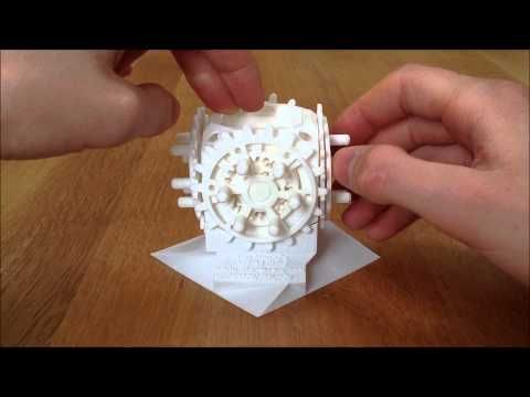
Print mechanisms totally assembled is one of the things that you can do with 3D printing. In this article, you will find what you need to be able to design and print models that have moving parts.
| EN | ES |
Before the appearance of 3D printers, prototypes and final products had to be manufactured using subtractive technologies, wherein the case of objects with mobile elements had to be manufactured separately and then assembled. With 3D printing, this is no longer a necessity thanks to the ease of creating mechanisms that have free spaces between parts, which allow their movement.
- The following design tips complement the Tips to designing 3D printable models to get moving parts.
Table of contents
- Space between pieces and tolerances
- Supports for the mechanism
- Improve mobility with post-processing
Space between pieces and tolerances
In 3D printing, objects are manufactured layer by layer so if the models were designed being in perfect contact, it would cause the extruder to fuse the pieces, creating a single object and preventing movement.
The best way to prevent the pieces from joining is by leaving a separation between the models when designing them, is recommended to leave a separation twice the layer height with which the 3D model will be printed. This space will be small enough not to be visible to the eye but useful for printing soluble supports in the area.
In the case of designing and printing the parts separately to later be assembled, the printing tolerances must be taken into account. Leaving a margin between 0.1mm to 0.3mm is usually enough so that the pieces have looseness, can fit together, and move.
Supports for the mechanism
Since the mechanism will have empty spaces between the pieces, in some cases it may be necessary to use supports to print the assembly.
The optimal materials to support moving parts are water-soluble due to the following advantages: they are removed by dissolving in water and they do not leave traces of materials that could obstruct movement between parts.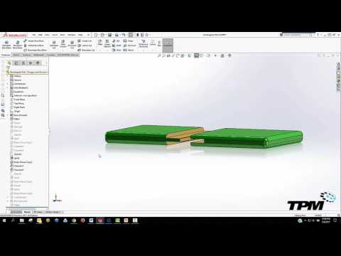
It is important that the piece has the necessary spaces and holes so that the water can flow between the parts and dissolve all the supports.
The supports of the same material of the piece are only recommended when the parts of the mechanism are printed separately since in case there are remains of material on the piece they can be post-processed.
Improve movility with post-processing
The smoothness of the movement of the mechanism depends on the surface finish of the parts, so in some cases, it will be necessary to carry out post-processing.
However, post-processing tasks can be complicated to perform depending on the assembly, since there may be a lack of space to insert and use the necessary tools.
If you have enough space or can disassemble the assembly, sand the surfaces of the model to be desired finish and mobility. This is quite beneficial when the layer height very wide, as this is the area where the greatest amount of friction will accumulate.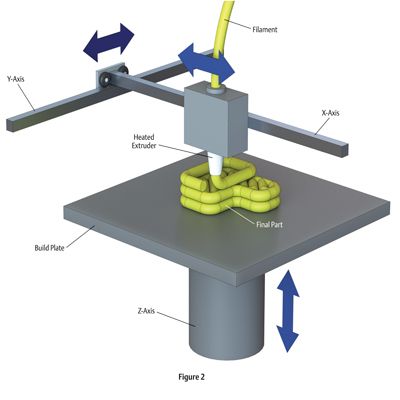
| Send us your comments about this article | |||
|
RELATED ARTICLES | |||
3D printing for the newest ones. From A to Z. Kinematics.
In this article, we will understand what 3D printing is and what the kinematics of 3D printers are.
1. 3D printing. What does she taste like?
There are a lot of printing technologies, from FDM (FFF), which is used by more than 90% of printers on this portal, to SLA / DLP / LCD (with photopolymers) and SLS / SLM (powder sintering using powerful lasers)
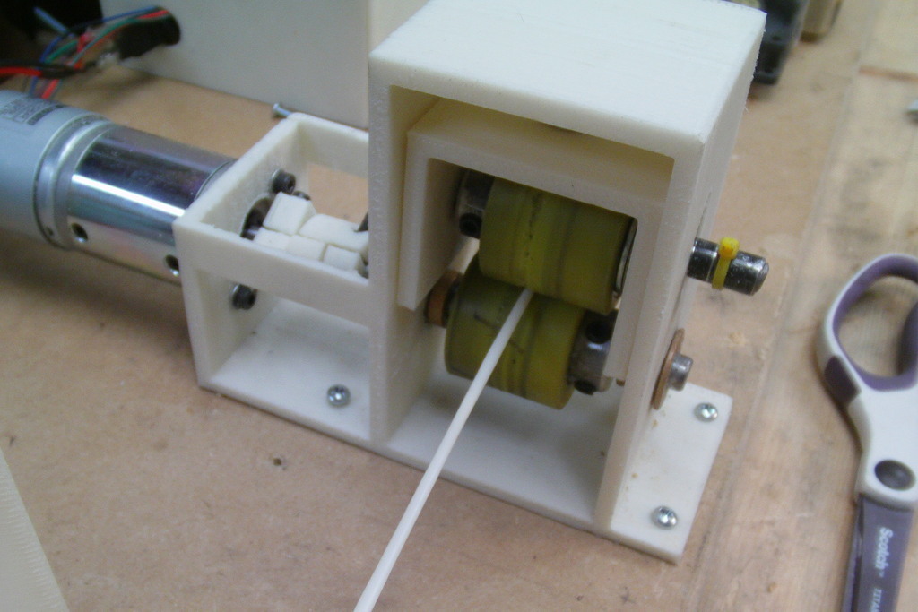
At the initial stage, we are interested in FDM - layer-by-layer deposition of a molten rod. The picture below shows the hot end (Hot end) - that part of the 3D printer extruder where the rod is melted.
The plastic rod is fed through the Teflon tube and radiator into the thermal barrier, and through it into the heating block. It melts there and exits through the nozzle. The nozzle has a certain diameter, which is marked on it.
It is often made of brass, as the material is inexpensive and easy to process. The accuracy of printing depends on the nozzle. The smaller the nozzle, the more threads fit into one mm.
Heater and thermistor provide feedback for temperature control and regulation. That is, the voltage supply to the heater depends on what temperature the thermistor shows, and the processor compares it with the set one.
Next we see the heating block. A nozzle is screwed into it on one side, and a thermal barrier on the other.
The thermal barrier is used to minimize the heating of the plastic above the thermoblock.
[IMG]http://3d-makers. nethouse.ru/static/img/0000/0002/6151/26151635.2ofdbr37y8.W665.jpg[/IMG]
Most often made of stainless steel. It has a lower thermal conductivity than conventional, unalloyed steel. To prevent the rod from melting above the thermal block, a radiator is screwed on top of the thermal barrier and blown by a cooler. Everything is quite simple.
It is very common for melted plastic to leak through threads.
This means that the nozzle has not pressed the thermal barrier in the heater block. Therefore, when disassembling and assembling the hot end, we first screw the thermal barrier into the heating block, and then press it with a nozzle. If, when you twist the nozzle, there is a gap between the end of the nozzle and the heating block, then this is normal, the gap in order to press the thermal barrier with the nozzle.
In order to feed the bar at the right time and in the right place, a feeder is needed, that is, a bar feeder.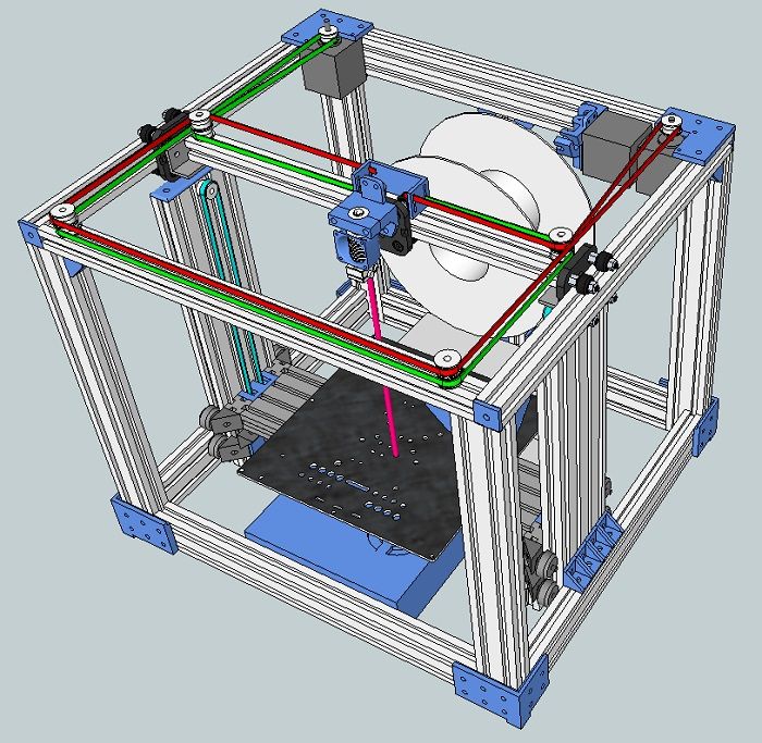
Sometimes it is performed combined with a hot end, and then this type of extruder (this is all together a hot end + feeder) is called a direct (direct), that is, a direct feed, without tubes.
The same feeder is made separately, and the bar is fed through a fluoroplastic tube. Such a system is called bowden.
This is to lighten the moving part. As for the positive aspects and disadvantages - each design undoubtedly has them.
Direct extruder:
1. Advantages:
a) More reliable due to fewer plastic feed connections;
b) Less picky about the materials it prints on, in particular rubber-based rubber is problematic to print on bowden extruders;
2. Disadvantages:
a) Large weight, due to this, during acceleration / deceleration, small ripples can be observed on the surface of the part;
b) Dimensions. They greatly affect the plot area. Let's say, like in the picture above, a direct with 4 colors would be very huge. And for Bowden, this is just right.
Bowden extruder:
1. Advantages:
b) The coil does not twitch after the model, otherwise, when the coil turns with the direct are entangled, we will get a skip of steps, since the carriage will pull the coil along with it.
2. Disadvantages:
a) Retract settings (pulling the rod back during idle movements so that the molten plastic does not ooze out of the nozzle while expanding) is more difficult, since the rod is smaller than the inner diameter of the tube, it tends to stretch;
b) It is more difficult than on direct to select all gaps in order to print with various flexible plastics. Everyone who says that printing on Bowden is impossible with flexible plastics is blatantly lying. I am typing. And quite successfully.
Now we go directly to the mechanics and its calibration.
Part 2.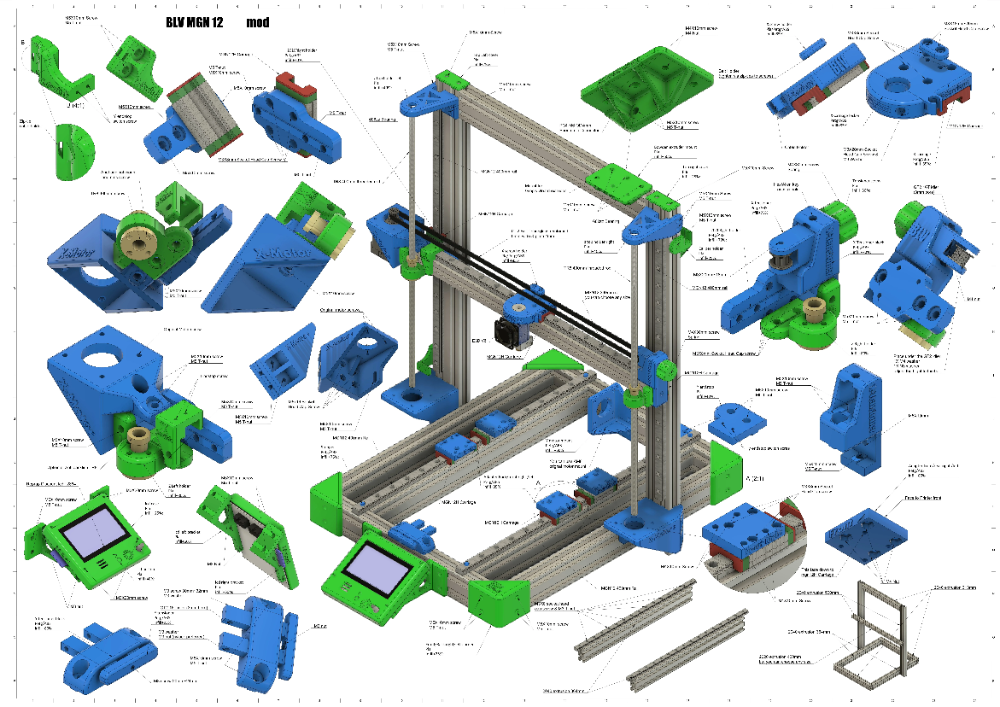 Mechanics. What, how and what pulls?
There is a very limited number of kinematic schemes for which the firmware is written, and which work out movements quite tolerably.
Consider everything, from the most common:
1. Design and kinematics from Joseph Pryusha (no need to read Prus, Prasha and so on, this is the name of a person, after all).
Movement along each of the axes is provided by its own independent motor. Movement along the Z axis (up and down) is provided with the help of 2 motors and with the help of a kinematic screw-nut pair. M5 studs are often used; recently, screws with trapezoidal threads have been increasingly installed.
Here is a trapezoidal screw. How studs with metric threads look I will not apply.
The only thing I will explain about moving along the studs and trapeziums is that for the production of trapeziums they take a calibrated rod and roll it between rollers at an angle.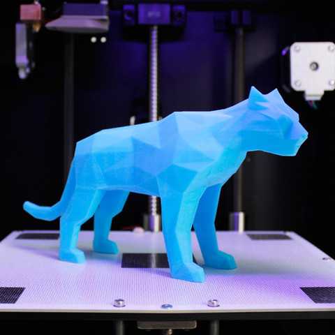 Get helical grooves. This method, a priori, gives better quality and step accuracy than building studs of far from the highest quality.
To connect 2 motors to one axle (and 1 connector) at the same time, the following scheme is used.
Connection in series, 2 wires soldered and the rest crimped. You can ignore the colors, the main thing is that the windings ring. A and B are windings, and 1 and 2 are terminals.
Advantages of this kinematics:
1) Independent movement of each axis. It is easy to catch to understand which axis skips steps. Kinematics migrated to printers from CNC milling, so many manufacturers make desktop milling machines on it, instead of an extruder they offer to install a laser for engraving or cutting, a spindle for milling boards, an extruder for chocolate or even dough to bake pancakes.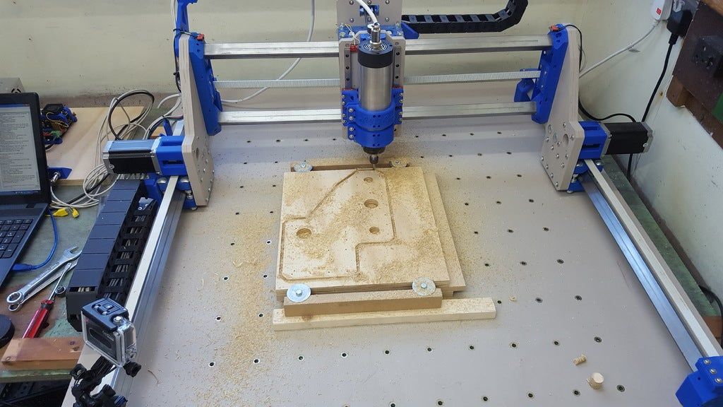
Pictured above is a ZMorph printer. It can be used as a printer (with one or two extruders), as an engraver (Dremel machine), as an engraving laser, and so on. A small presentation video.
Milling machine with this kinematics. I note that for milling it is necessary to use a screw-nut pair to move, and not belts, they are not designed for such loads.
Chocolate and pancake printers according to your design. It is worth noting that it is not recommended to use chocolates like Alenka or Babaevsky, since they already contain cocoa butter and during processing (melting and hardening) the result is unpredictable. It is necessary to use chocolate in galettes, such as the Belgian Callebaut, as it does not contain cocoa butter, and must be added for the final filling.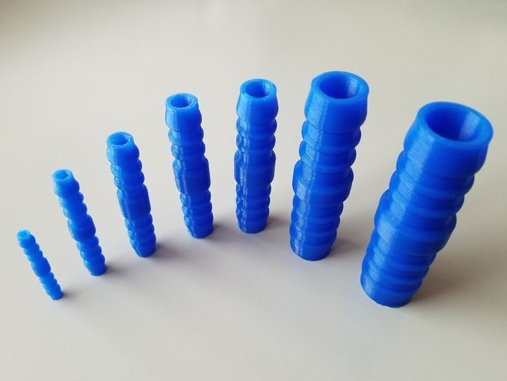 For this type of chocolate, each pack has a graph of its crystallization. It is desirable to take the oil in powder form. For more information, I recommend Google about tempering chocolate.
2) The kinematics are as easy as two fingers. Its very easy to assemble. Many even collect on old DVD drives.
3) Easily changed to suit your needs, the size of the extruder is also of little importance, as it protrudes forward and does not interfere with the movement of other parts. Many people put a second extruder, or make the nozzles swing so that the nozzles of one extruder do not remain on the part when printing with the second nozzle.
Therefore, for this kinematics, there are a huge number of extruder variations, for every taste, on a very famous site.
Disadvantages of this kinematics:
1) Complicated calibration. Yes, since the table 'jumps', it is difficult to print with high quality, because the part + table, with a sharp change in the direction of movement by inertia, tend to go further. Ugly print artifacts are obtained. And for high-quality printing, you need a small speed. In general, it all depends on the frame. My first printer was a Chinese pryusha. With acrylic frame.
Acrylic is not very hard. And as you know, the rigidity of the printer, like the CNC, is the most important thing. And it was possible to print more or less qualitatively at speeds of 40-50 mm / s. Then I transplanted it to a steel frame from MZTO.
And after that, without loss of print quality, I was able to print at speeds up to 100 mm / s.
2) Delamination. Due to the open case and the constantly moving platform, hot air, one might say, is constantly blown away, and by cooling the part excessively with drafts, we increase the already large shrinkage of nylons, abs and other capricious plastics. Someone sews a fur coat for a fabric printer, and someone is content with boxes.
But the goal, as always, is the same - to reduce the effect of drafts on the shrinkage of the part.
Key points for correct calibration of printers with this kinematics:
1) Place the printer on a level surface. Preferably horizontal. This requires a bubble level. Next, set the level of the position of the X axis.
2) Transfer to the home position. It is done either in the printer menu with the Home / Home command, if you are printing from a computer, then either with the G28 command in the command line, or with special buttons with the house icon.
Next, tighten the table screw so that the nozzle touches the glass. It did not press on the glass, but touched. We look at the light and twist. After that, move the extruder to another corner with the arrows in + X, + Y from the PC, or through menu
Turn the screw in the same way until it touches the nozzle. And repeat the operation for the remaining points.
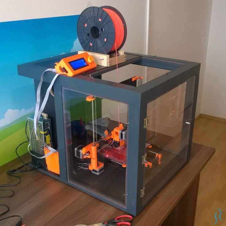
I will try to save you from mistakes. In the photo of the printer above, the glass on the table is fastened with as many as 8 clamps. And it is quite possible that there will be a hump in the center. To avoid such problems, the glass should be fixed with 3 clamps. The plane is built, as is known from descriptive geometry, by 3 points. And calibration will be easier in this case. Just tighten the screw over the limit switch in Z.
For the nozzle to touch the glass in the middle of the side with 1 clip. Then we distill the hot end into the corner where there is another clamp, tighten the table screw, and repeat the operation with another angle.
Regarding wobble.
All sorts of anti-wobble systems such as installing a bearing in the upper support do not work.
Just because putting 4 far from perfectly even cylinders in perfect parallel and in the same plane is an unrealistic task. Especially on a flimsy acrylic frame with printed details. Therefore, if we take the straightness of the shafts as a constant, and set them parallel on the frame (purely hypothetically), and release the screws (from below the coupling for attaching to the motor) and nuts for attaching the X axis. Due to their curvature, the screws will spin like a mixer, but on printing will not be affected.
Otherwise, the design will work on who will be stronger in terms of bending resistance. And it will turn out far from a flat wall. Do you need it?
2. Kinematic design of Felix printers.
There are many such printers, such ones are made by MZTO (mz3d.ru), already mentioned by Felix. In fact, the kinematics are the same as those of the Prusa. axes independent of each other. Only now the table does not travel along one axis, but along two at once. Along the Z axis, and along the Y axis.
The design of the table is something like this.
A platform rides on the Z shafts. The engine hangs at the back. The table moves along the rails with the help of a belt. The hotend moves only along one axis. The design is very funny, since the table weighs much more than the hotend, and they try to move it along 2 axes at once.
Advantages of this kinematics:
1) There is no second motor along the Z axis. There is no notorious wobble simply because there are 2 shafts and 1 propeller. The screw should also not be fixed from above. If it's not a ball screw.
Ball screw is a separate issue. If we take a high-quality ball screw, say, from the same Hiwin, then it is manufactured according to at least the 7th accuracy class (if rolled, and if polished, then the class is even higher) and must be installed in bearing supports. On the drive side there are 2 back-to-back angular contact bearings, and on the other end a radial bearing with a loose fit to compensate for thermal expansion.
The purpose of mounting a ball screw is to ensure movement accuracy. If it is installed incorrectly, money is wasted, and the accuracy will not be higher than a screw-nut pair with a trapezoidal thread. For FDM, trapezoidal accuracy is more than enough.
2) Plenty of space for a direct extruder. As in the previous kinematics, there is room for creativity, to select the one and only extruder that you like.
3) Rigid frame. It is possible to make a normal frame. Rigid, durable. Yes, even cast iron. The guys from Felix decided not to bother their heads and sculpt from an aluminum profile. MZTO went further, bent the steel sheet. And the shelf for the installation of the table was milled from a sheet of aluminum.
4) If we take the design of Felix on the profile, then by replacing a pair of pieces of the profile and the Z screw, you can increase the print area.
Just be sure to add stiffness. And it will turn out like a miracle of design thought. Big, meaningless and merciless.
Kinematic disadvantages:
1) Undoubtedly large twitching masses. The table back and forth, and if you turn on the movement along Z during idle movements (Z-hope), then there will be a disco.
2) There is no way to make him a normal heat chamber. The table moves back and forth and the temperature gradient simply blows away. Hence the problems when printing with nylons or ABS. Small drafts in the room will easily show you where the crayfish hibernate, how the material shrinks.
The calibration of the table of this printer is similar to the calibration of the Prusa table, only slightly simpler. It is easier due to the fact that you do not need to level the X-axis, it is automatically set when assembling the frame. We bring the nozzle to the table and twist the lambs.
3. Ultimaker kinematics.
One of the most common variations of Cartesian kinematics.
There are not very many such printers, but they do exist. Variation from Zortrax deserves attention. A variant of the same Raise is closer to the classics.
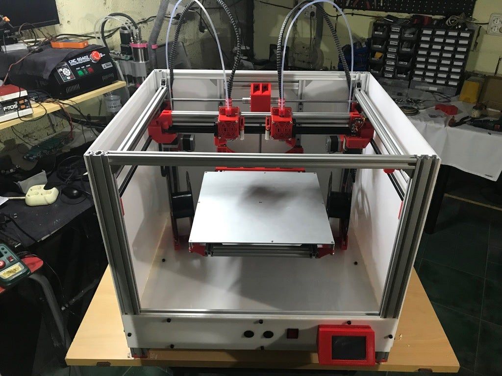
Zortrax has twin shafts, the reason is simple - they have a direct extruder with a full size Nema 17 motor. Raise Dual has a double direct extruder, so the classic 6 mm shafts are replaced by 8 mm. And the total weight of the 'head' is almost 900 grams.
Kinematics built entirely on shafts. They act both as guides and as pulleys. Kinematics also refers to Cartesian kinematics with independent movement along each axis by its own motor. Very picky about the straightness of the shafts. If you use curved shafts, you can get very funny artifacts on the walls of models. And they will be on all 3 coordinates. Most often it looks like a different thickness of the first layer and small waves along the walls. Therefore, all the salt and the high price of the original Ultimaker is only in high-quality components. Namely, in straight shafts. The belts are often used as ring belts, which simplifies their tensioning system, since it is important that all 4 belts are equally tensioned.
Advantages of this kinematics:
1) The table only moves along one axis. vertical. And the temperature gradient in no way suffers from this. The table is cantilever, so it is desirable to provide stiffeners or take this into account with the thickness of the table.
The metal fold on the table acts as a stiffener.
Many Chinese clones are equipped with such stiffening ribs for the table.
2) Despite the seeming complexity of the kinematic scheme, it is simple and each axis moves with its own motor.
3) The body is closed, which protects against drafts, and therefore delamination. Some put an acrylic door to heighten the effect.
Disadvantages of kinematics:
1) For good printing, it is not enough to buy a pack of even rollers. Collecting all these shafts correctly together is another task. At the same time and buy good bearings. Not that, Chinese junk, which is often sold on Ali, but normal bearings. If the bearings that are placed in the housing rotate poorly, the print will be jerky and with a shift in the layers. The consequences can be asked from Vanya (Plastmaska). Also, when buying leopard bushings, brass bearings with graphite inserts, be prepared for the fact that they will play. And if there is a backlash, the whole structure will knock.
And also, the Chinese like to push brass instead of bronze. And with even wear of brass and graphite, there will be an oily sticky black film on the shafts, which will make the movements harder. Ilya (tiger) offers good bushings. He also wrote about these difficulties.
2) All shaft parallels must be set correctly. I suggest using this device.
4 shafts that go along the walls of the body automatically stand up correctly, but it is important to set the crosspiece correctly in order to get angles 90 degrees in the XY plane.
3) The design does not provide for an increase in the printable area with a couple of profile pieces, so the size of the hotend matters. Direct is difficult to put, but you can if you want.
Calibrating the table couldn't be easier. The table is often on 3 attachment points. Move the hot end by 3 points and turn the thumbs.
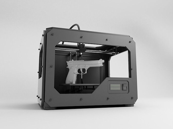
4. Kinematics used by Makerbot.
Also very widespread. In particular, printers from Makerbot, BQ, BCN3D, Magnum, magnum clone Zenit and quite tolerable makerbot replicas Flashforge and Hori work on this kinematic scheme.
In this case we have independent movement of each of the axes, with a Z table and all the resulting sides.
The main drawback is that the engine hangs on one side of the rolling beam, creating a kind of imbalance. This shortcoming was compensated in a two-extruder version - BCN3D Sigma. There, each bowden head has its own engine to move along the beam. And they are installed at the edges of the beam and balance each other. For uniform movement of each of the edges of the beam, 2 shafts, pulleys and belts are used. Belts must be tensioned equally.
Advantages of kinematics:
1) Independent movement of each axis.
2) Z-moving table. The temperature gradient does not suffer from 'blowing'.
3) Enclosed body. If not closed, then there is a quite normal chance from the point of view of aesthetics to close it.
4) Scalable kinematics possible. Various BigREPs and others with 1m print areas use exactly this kinematics, as various H-bot/CoreXYs will ring like hell due to the presence of 4-5m belts and their stretching during accelerations.
Disadvantages of kinematics:
1) Unbalanced masses on the moving beam, hence the maximum print speed, with acceptable quality no more than 60-80 mm/s. Some manage to balance them and it is not so noticeable.
2) Bulky structures on the shafts to avoid unbalance during movements.
3) Make sure that the belt tensions on the right and left are the same.
4. H-bot/CoreXY kinematics.
Next in distribution. Also Cartesian. Two motors are stationary, but move the carriage along the rails with one long piece of belt, or with two, but shorter. The math is more complicated than the previous ones, as it is necessary to synchronize the rotation of both motor rotors. That is, to move along each axis, you need to rotate both motors, and to move diagonally, only 1.
[IMG]http://www.doublejumpelectric.com/projects/core_xy/pics/hbot.svg[/IMG]
In fact, the mathematics for rotating motors is the same, but the implementation in mechanics is different. One of the biggest disadvantages of the H-bot over the CoreXY is that the belt tends to rotate the beam as it moves.
In the picture on the left, this is noticeable, the forces on the right and the forces on the left create a torque. Therefore, to implement this kinematics, the rigidity of the kinematic scheme is necessary.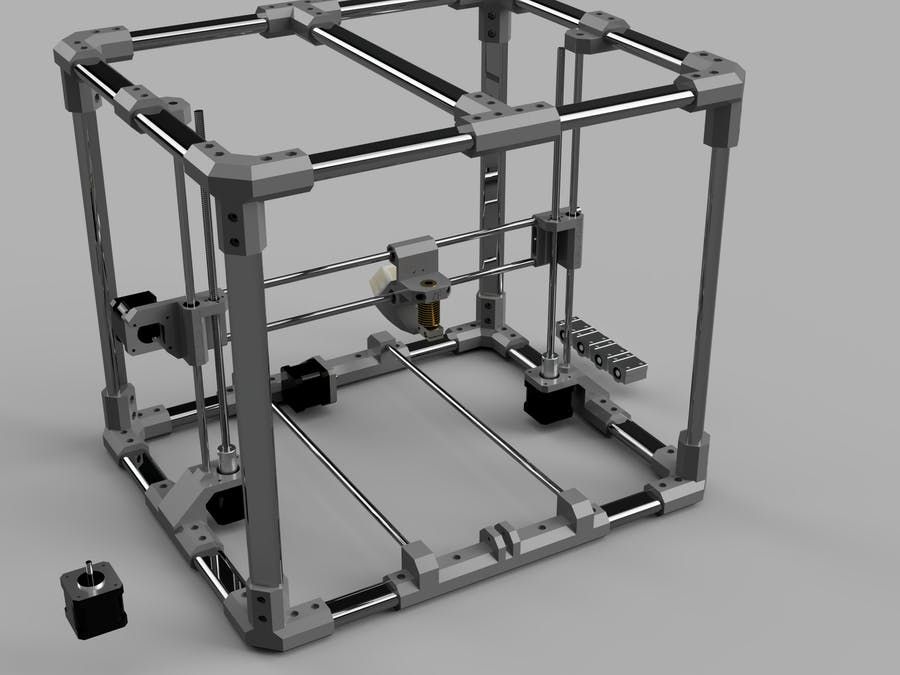 Most often it is implemented in rails.
With rigid beam. Some do, of course, on the shafts, but in the end - this is not a fountain.
And then they realize this and move to the rails.
For they are both easier to assemble and set up, and it is not necessary to invent carriages so that the shafts do not need to be fixed well.
CoreXY, unlike the H-bot, is driven by two belts.
And so, for ease of understanding, I will describe the positive and negative aspects of each variation of this kinematics.
H-bot.
Advantages:
1) Only one belt is needed, and the scheme provides for its operation without twisting.
2) It is more convenient to tension one belt than 2, so only one normal tensioner is needed in this scheme.
Even so.
Disadvantages:
1) The belt tends to stretch over time, and since the amount of stretching directly depends on the length, it is necessary to monitor its tension. Otherwise, you will get ugly waves on the surface before the stops.
With a loose belt tension, the carriage will have this play.
2) It is necessary to set the rollers strictly perpendicular to the XY plane, since if the roller is slightly skewed, the belt will be eaten against the roller shoulders. And we will get such a bullshit.
Tested in the skin and ZAV printer. Therefore, I always recommend that the rollers be fixed normally, and not cantilevered, in order to avoid bending the roller axis from belt tension.
3) Complicated mathematics, due to which at speeds above 100 mm/s there may be problems with the lack of resources of 8 bit boards.
CoreXY.
Advantages:
1) Two short pieces of belt. They are easier to find than one long one.
2) The forces balance the beam, but do not tend to turn it, so these kinematics can also be assembled on shafts.
Disadvantages:
1) There are schemes with belt twisting and belt transition from one level to another - this is not very pleasant for a belt. Especially when one belt rubs against another. This moment is on video.
:{}
2) The difficulty of tightening the belts. They must be tensioned equally, otherwise the tension forces will tend to turn the carriage.
3) Complexity of assembly and development. It is necessary to maintain the verticality of the rollers, relative to the horizontality of the platform for installing motors and rails. A slight misalignment of the rollers will cause the belt to tend to slide down the roller, and if it rests against the shoulder of the roller, it will creak, if the shoulder is large, and if it is small, it will try to drive into it, as in the photo from the h-bot description .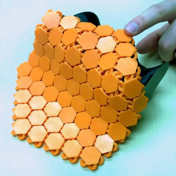
The general disadvantage of kinematics is poor scalability. That is, it is very problematic to set such a kinematics for a print area larger than 300 * 300 simply because of the lengthening of the belt during printing. For small printers with high print speeds - one of the best kinematics.
5. Delta kinematics.
The kinematics are based on the movements of the delta robot.
Only the hot end is installed instead of grippers. It has its own set-up problems, but it can take a very long time to print. It is rare when direct extruders are installed, since the effector (a platform for installing a hot end) is often mounted on magnets and it is necessary to unload it as much as possible. But to reduce the length of the tube (more specifically, the effect of the length of the tube on the print quality due to the correct adjustment of the retracts (pulling the plastic rod back to reduce its leakage from the expansion)) on the print quality, the extruder is hung on the same carriages, but on separate hangers. This reduces the length of the bowden tube and increases print quality.
Advantages:
1) Easy to customize. To increase the height, it is enough to buy 3 pieces of a longer profile, and increase the maximum height in the settings.
2) Takes up little space. It is more often high than bulky in length and width, due to this compactness.
3) If you make a light effector (carriage on which the hot end is installed), then you can achieve high speeds without losing print quality.
4) Vertical movement is the same as XY movement. Thus, there is no sticking of linear bearings on the table crossings, as in Cartesian printers, no extra motors rolling on the beam...
5) The absence of protrusions makes it possible to close the housing and stiffen the frame.
6) The aesthetic part - it's more interesting to stick to the work of the delta.
Disadvantages:
1) Difficult mathematics of movements, it is recommended to install 32-bit boards at once.
2) Complicated setting. A common problem in tuning is to remove the so-called 'lens', because each rod rotates with a radius, and if the tuning is incorrect, your printed plane will be either a convex or concave lens.
3) It is difficult and expensive to make a rigid frame, so that it would not dangle from the constant jerking of the carriages.
4) Difficulty installing a direct extruder. It turns out to be heavy, and since many deltas are made on magnets, it will not be possible to accelerate. Although, there is one neat and easy solution - installing a ready-made direct extruder with a gearbox. Like E3D Titan Aero or Bondtech BMG.
5) Parts precision problems - any unevenness and misalignment will be visible even if they are on the same axis. And they add up along the axes.
To sum up , do you want a small printer (not larger than 300*300 mm) with nimble kinematics? Then you should go to Ultimaker or H-bot/CoreXY. Need a printer with a large printable area or 2 independent extruders? Then to Makerbot. If you print vases, hookahs and sufficiently high details - delta. For everything else, there is a classic - Prusa. Experiments with double carriages, chocolate, engravings? Yes, anything. And most importantly - cheap.
You can even screw on 4 colors.
How to 3d print another 3d printer
Already have a 3D printer? Want another one?!
Why is this needed?
Well, let's say you have your own large printer and you can print fairly large objects. Do you believe in the idea of the reprap movement, the printer should be able to reproduce itself!
Or you want to challenge yourself and finally understand how the 3D printer works.
Or your current 3D printer is just sitting around gathering dust in the corner of the room, because you have already printed everything that came to mind, and the most difficult task that worries all 3d printing professionals is how to clone existing equipment on itself.
Step 1: Preface
Let's be honest... the is not the ultra cheap printer. This is not Chery 3D printer for $60. This not is a way to save money or time. This is not first printer.
Now let's talk about what is .
B 3Dtje mini 3D printer is:
- Damn easy to print
- Printed parts made of PLA
- Everything fits within 200x200 print volume
- Most parts can be printed in 100x100 print volume
- Most parts are printed without supports , only in some cases they may be needed to improve the quality of
- Very few few needed tools
- Unlike most crafts that require a laser cutter, the CNC
- You can probably get away with a drill and a hacksaw to prepare 2 rods of the required size
- No source of MDF, or wood, or acrylic sheets or aluminum profiles, which can cost a lot
- A Prusa i3 Clone
- This design is not new, nothing revolutionary, but it is reliable, prints well and works with any slicer
- Open source
- All model files can be downloaded free of charge
- You can download them and modify them as you like
- You can even sell them if you need to!
- Simple and interesting printing
- 19 models
- All parts are different and look very interesting together
- Easy to assemble
- All parts are connected with M3 screws and nuts.
- Cutting 2 to 4 metal rails
- Some 3d printed parts are assembled intuitively , you can even ignore photo
- All parts are connected with M3 screws and nuts.
- Really fucking cool!
- Small, portable, low moving parts! This printer can print fast! (when properly configured)
- This 3D printer you will DIY , completely!!
Let's get started!
Step 2: Prerequisites
You will need a 3D printer , well, or find someone with this device.
- Printable area must be at least 200x200mm XY and maybe 200mm Z if you want to print with refills
- PLA 1 kg, can be different, but this is the most convenient option
- I honestly don't know how much it will take. Likely 500g or so
- Tools
- Screwdrivers for screws
- Pliers, cleaning tools for printed objects (a clerical knife is sufficient)
- Metric drills for opening / cleaning the printed hole (you can also use a screwdriver)
- knowledge of how to build a 3D printer from scratch
- These are not hard requirements, but knowing how to deal with common printer problems will reduce the amount of swearing when things aren't perfect the first time.

- If you understand firmware Marlin it would be very cool to talk about this, as there is a desire to improve some things.
- These are not hard requirements, but knowing how to deal with common printer problems will reduce the amount of swearing when things aren't perfect the first time.
Step 3: Parts
First off, I've made a list of exactly what you need and what you can buy to make the best possible quality. But it will be more expensive. Therefore, you choose which set to buy - in principle, they will not differ. In addition, you can order all this from China, it will be cheaper, but the wait will be longer. In any case, you need to look for all the components in English, so we take them from the table and, for example, insert in alliexexspress search .
The table is located at this link.
Step 4: Printing Parts of
Now let's move on to the most interesting part, in my opinion - prototyping models of . To be honest, I really like to print different things, you feel that you can handle any task when you have a 3d printer at hand.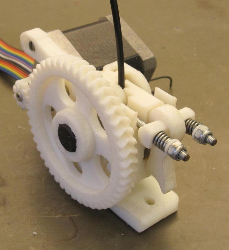 Okay, it's all lyrics.
Here is located the project itself, where you can for freedownload 3d models for printer. Download and start preparing for printing.
The most important thing is to arrange the parts correctly on the table . The idea is to make the models have as few parts hanging in the air as possible. This will allow to drop support for . After all, they spoil the quality very much if you do slicing through Repetier Host with their auto-generation, and not draw them yourself.
You can watch a video showing the optimal arrangement of parts. Print settings I think you know how to do it, if not - there are articles about it with configuration files.
Step 5: Mounting
Assume we have printed everything. Someone may have decided to use metal guides, buying them, for example, from IKEA, and cutting them into sections of the desired length.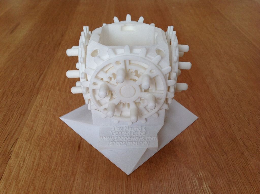 In any case, writing how to assemble this 3d printer does not make much sense, and it's too lazy, to be honest. In my opinion, there is nothing better than pictures!
Frame Assembly
First I'll lay out how our miracle should look like at the moment of medium readiness. Then we will see how the modules were assembled.
Assembly of the Y
Axis. This Axis drives The so -called bed . First we need to install the motor, put on the pulley on it. Then we install a freely rotating pulley on the other side and measure 9 for them0409 belt .
And now we will install the bed itself, which will fasten the two ends of the belt to us. Just don't forget to tighten the pulleys and anything that isn't tight yet. The substrate will be massive and it will be inconvenient to crawl there already. The connection will require 200mm x 6mm bolts, so have them ready right away.
It should be noted that the belt must be very tight . This will greatly affect the print quality of the . If you cannot do this at the time of assembly, you can use special tensioner . It's basically a simple spring. As for the axes, in this case they are printed, although this is far from mandatory, just the name of the project obliges))
X-axis assembly
Depending on your printer, you may need to make a hole with a 3mm drill in the belt tensioner. This hole should be quite free.
- Attach the motor to the end of the x-axis with the connector down
- Attach 20T gear
- Insert 6mm 6mm x 180mm rods into the holes on the motor side. You need to cut these rods if you bought 200mm.
- Assemble the x-axis tensioner with either your own or printed tensioner bearing.
 Make sure the m3 nut is in the tensioner before proceeding.
 - Pass the belt from the left side (engine side), through the gearbox, through the idler bearing to the right side
- At this point, install belt tensioner to the right of the x-axis on the rods
- If you are happy with the length (make sure the x-axis of the tensioner is recessed quite a bit) you can cut the belt. Don't forget to leave extra strap length
- Attach LM6UU bearings in bottom bracket x
- All assembled, attach the straps to the carriage x
- Then it remains to adjust everything a little to make sure that nothing touches each other
Assembling the Z axis
Now we assemble the Z axis. If you have not installed the engines in the course of past work, it's time to do it. As you understand, they should stand on the left and on the right. We will install adapters for screw rods on them, where we will put them, holding them with a hexagon.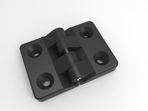
We stick the guides (parallel to the screw rods). We can say that we have finished assembling the case.
Step 6: Assembly of the electrical circuit.
How to lay the wiring is everyone's business. Here the options will be shown in the photo, but it's up to you to decide. The most important thing is to connect everything correctly. I’ll also post the diagram, but it’s better to see how it is done in ordinary 3d printers. For example, in order not to go far, you can go over the following articles directly on this site:
-
3D printer learning
-
3D printer setup and calibration
-
Ramps 1.4 connection in 3d printer
It is not necessary to read everything - you can see the key places from the pictures and delve into their study.
The picture below shows the green power terminal. This is a very dangerous and unreliable thing that sometimes ignites - it is dangerous to leave a working 3d printer at home unattended. Therefore, in an article about Ramps, it is better to read how to be in this case.
Step 7: Firmware
Since you will (most likely) have an Arduino Mega as the brain of a 3d printer, uploading firmware to it will be quite simple. All you need is the Arduino IDE. The most standard firmware from Marlin. The main thing is to choose the correct configs for the board. I have not seen an article about the firmware on this resource, but it can be easily found on the Internet. Here are useful links:
- Firmware Marlin manual
- May be useful to someone info about reprap electronics, how it works
Step 8: Testing
Finally time to print something! We note right away that the table must be covered with molar tape or Kapton, since we have it without heating.