3D print landing gear
3D Printable Landing Gear - Nose Gear Version 1
RC Airliners
Written By Terrance Luckett
Work has begun on the 3D printable nose landing gear for the L-1011 RC Airliner
Initial Fitting and Kinematic Modeling
View fullsize
View fullsize
View fullsize
View fullsize
View fullsize
View fullsize
About the Design
I have designed the nose landing gear in a way that allows it to be fully assembled independently from the fuselage frame. Once assembled it will slide into the gear well as one component and then secured in place with either 3mm screws or, for a permanent installment, 3mm pins/wooden dowels.
For added strength the landing gear has steel reinforcement embedded within the 3D printed parts, mainly the strut and trunnion, to ensure a stiffer more shock resistant part. Various materials will be tested to ensure durability, easy of printing, and resistance to heat.
Testing will be done using the following 3D Printing materials:
Nylon
Carbon Fiber Filled Nylon
Polypropylene
Glass Filled Polypropylene
Carbon Fiber Filled Polypropylene
Nose Landing Assembly
View fullsize
View fullsize
View fullsize
View fullsize
View fullsize
View fullsize
View fullsize
View fullsize
View fullsize
View fullsize
View fullsize
View fullsize
Made good progress on the nose landing gear design for the L-1011 this week.The assembly with housing can be assembled independently and installed into the frame in one piece. #3dmodeling #engineering #aviation pic.twitter.com/YpMuAXMm6E— RC CAD2vr (@cad2vr) July 30, 2021
@rccad2vrSurvive a hard airplane landing? ##engineering ##mechanical ##mechanicalengineering ##industrialdesign ##aviation ##airplanes ##uav
♬ Blade Runner 2049 - Synthwave Goose
@rccad2vrIt's ready for the 3D printer ##mechanical ##3danimation ##aviation ##landinggear ##engineering ##airplanes
♬ Ambient-style emotional piano - MoppySound
Interactive 3D Model Landing Gear - Version 2
Kinematics
Kinematic Motion Study of the Nose Landing Gear for the RC 1:20th Scale L-1011-500 Airliner. In this video the articulation and gear bay door sequence it tested for proper obstruction free movement.
These two images show an early version of the design where the kinematics for the landing gear were determined to ensure clearances and proper placement of the trunnion and tire clearances.
View fullsize
Nose Section Landing Gear Profile Kinematic View
View fullsize
Nose Section Landing Gear Quartering View
3D RenderingLanding GearL-1011Mechanical Engineering
Terrance Luckett
From my very first flight from Germany to the United States as a young kid, I’ve had a love of aviations. Even today, my mind is always thinking about airplanes. Join me as I document and explore aviation, from model to full scale.
https://www.tiktok.com/@rccad2vr?
1st 3D Printed Airplane Landing Gear Prototype
Prototyping3D Printing
Written By Terrance Luckett
After spending months in CAD designing the RC scale model of the L-1011 Airliner, also known as the TriStar, I am finally moving on to the prototyping phase of this project. The very first prototype model I’ve printed on the 3D printer is the landing gear assembly. It was printed using PLA white and PLA red.
Prototype Version 1
In the images below, the landing gear components only include solid parts, so the tires where left off in this model. I will be printing them with TPU later on when I finish making adjustments to the wheels.
Outboard Landing Gear Face
This is the outboard face of the landing gear which was printed using the Raise3D Pro 2 3D printer at a standard resolution.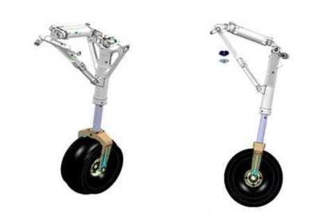
Front Landing Gear Face
This is the front face of the 3D printed landing gear assembly. The side stay function as expected and places the gear in perfect extended position.
Inboard Landing Gear Face
Here you can see the inboard face of the 3D printed prototype. Notable is the side stay arm which extends into the fuselage. This was a tricky area and based off of images of the L-1o11
This design incorporates a trunnion and bearings system as a rotational axis to move the gear from retracted to extended position much as they are on full scale airliners. I opted for this design to stay truer to life and to challenge myself by not buying off the shelf landing gear. It has come with its challenges, but make the model more fun to build.
Having this functional model prototype to play with has already lead to several changes. Most notably, the method of actuation by way of a standard servo proved to be incapable of moving the gear into the retracted state.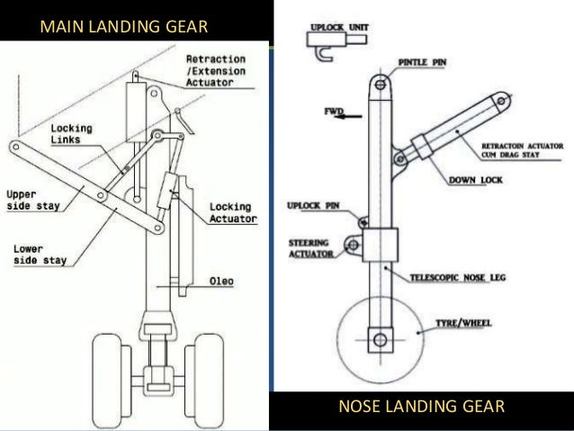 Due to the position of the linkage arm between the servo horn and lever pin, which attaches a few millimeters above the trunnion, the last 5°-10° require too much force. A servo that size simply will not have enough torque to get it to the final 90° position.
3D Printed Landing Gear Housing Structure
The red material is the housing and structural mounting bracket for the gear bay inside the wing. The angles and pitch match the wing top and bottom skin surfaces.
Interior Landing Gear Housing and Mounting Bracket
Looking down into the gear support structure and housing you can see black wires. These are to check for clearances and routing of wires to ensure they do not rub or catch on any moving parts.
Retracted Landing Gear Top view
Looking straight down on the gear assembly, this shows how it looks in the fully retracted position. The right wall of the housing is the root of the wing mount, everything right of it will be inside the fuselage.
As I continue working on the landing gear, I will be posting updates to this post with more photos and diagrams. Follow me on IG and Twitter if you are interested in regular updates and progress on this build.
3D Printing3D PrintedLanding GearPrototype
Terrance Luckett
From my very first flight from Germany to the United States as a young kid, I’ve had a love of aviations. Even today, my mind is always thinking about airplanes. Join me as I document and explore aviation, from model to full scale.
https://www.tiktok.com/@rccad2vr?
Printed RC Car Chassis
3D Printed
Subscribe Author
Subscribe
Don't Want
39
I've been interested in RC models for quite some time now. In the process, it turned out that I was no less interested in disassembling and assembling, repairing and modifying cars than driving them. So maybe develop this hobby and compose your own chassis, where the lion's share of the parts will be printed?
So I did. And in the end he composed twelve versions of the chassis. Now an acute desire has settled in the body to share its achievement. At least briefly.
At the very beginning, it did not seem difficult for me to draw a model. I thought it was enough to make a copy of some existing shashka. How wrong I was. 3D printing imposes a lot of restrictions on the shape and size of products. Therefore, it is not possible to make a complete copy. But I did not understand it right away, but approximately by the fourth version of the platform. In addition, at that time I was an inexperienced printer, and did not always understand how best to draw a part and position it when printing. But still, I got something.
I will not describe all 12 versions, if only because the photos are not for all models. And there are much fewer radically different versions.
- Stage 1
This was the first version that rode confidently and did not break on every bump. Here I abandoned the use of printed differentials, axle shafts and drives. Why is that? Because on plastic parts it was not possible to roll one battery. Parts were broken and worn. I composed a huge number of drives and axle shafts. But no, I could not overcome this problem. In addition, at that time there was a low-powered collector motor, which means that with a brushless motor, the problem would have worsened even more.
There was a difficulty in choosing metal parts. I only had a rough idea of what I needed. That's why I chose pictures. And not all the details came up the first time.
- Stage 2
Next milestone. The photo shows the model after a serious crash. For some reason the other photo didn't survive. The model has acquired a crust and all-wheel drive, the wheels have grown. The chassis has been completely redesigned. Errors of all previous models are taken into account. As a result, strength has increased significantly.
- Stage 3
It was then that we needed bigger wheels for our roads. This means that you need to change the class from buggy to truggie, as a result, the width of the model changes, which means you need to use new drives. Some parts have become even thicker and stronger, but in general, not so much has changed. Plus a new trendy crust =)
- Stage 4
Here it is, the final model! There are many changes in this version of the chassis, and it is worth dwelling on them in more detail. Up to this point, I have used 1/10 scale parts in my crafts. In addition, the choice of parts was not so rich. Most of it was from the Chinese HSP, and on this scale their strength is lame on both legs. It turned out that metal products began to break, and my plastic case remained intact. Of course, I was a little proud of this, but something had to be done to increase the strength, otherwise the moment came again when it was not possible to roll one battery to the end.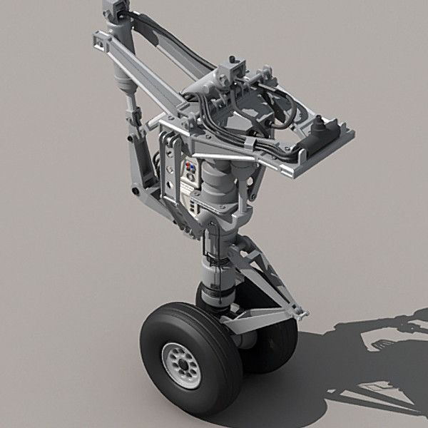
Here I decided to use the drive and axle shafts from 1/8 scale. Of course, it was the same Chinese HSP, but, firstly, the parts were thicker and more massive, and secondly, in this scale, the spare parts were of better quality.
This model made it possible to roll several batteries without breaking. And all crashes occurred during serious collisions and falls. And then, whatever one may say, there was nothing to blame her. I was satisfied with this chassis and decided to stop all further improvements.
Small crash test roller.
- Stage 5
Accumulated experience with 1/8 scale parts. I already knew what I needed, where to get them from, what sizes the spare parts had. And therefore it is necessary to compose a completely new chassis in this scale.
The output was three differentials, hefty wheels, about 4kg of gross weight and a speed of around 100km/h.
But it lacked some kind of racing. Which means something needs to be improved. And so another version was born. Which so far is only as a render.
- Stage 6
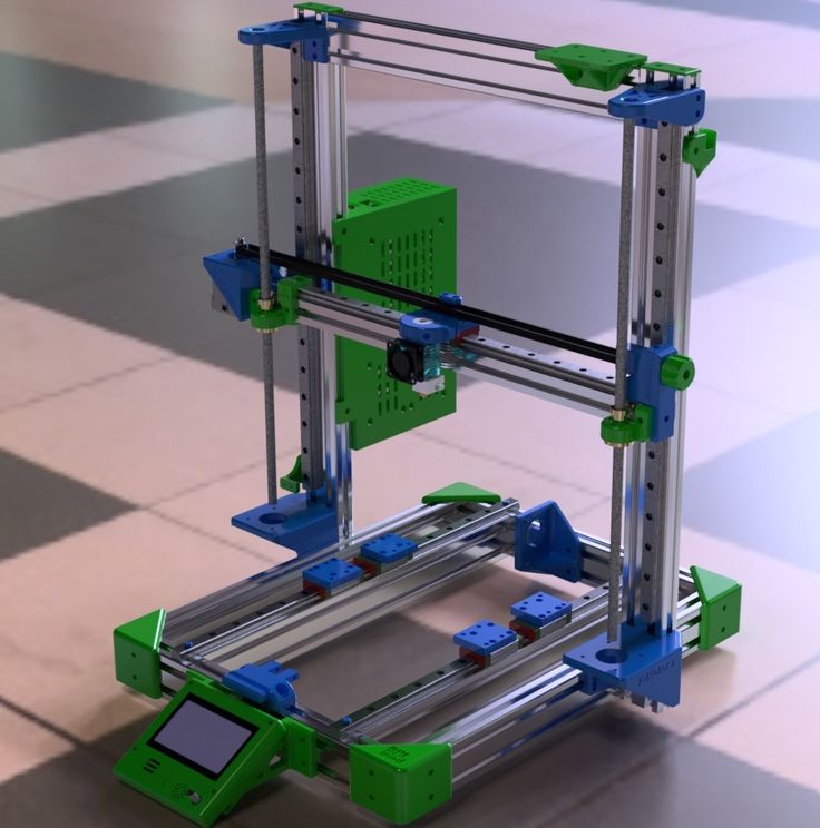
Since there is no working model yet, it will be brief. The printed frame was replaced with a frame made of aluminum profiles. The chassis has become somewhat longer and wider, which should add "racing". In the future, even more powerful motor.
That's all a brief description of my hobby. At the beginning, I wanted to describe in more detail about my journey from thorns to the stars, but after I made a description of the development and refinement of the first chassis, I realized that this was a titanic work and could not be pulled at once.
Thanks to all those who read. I tried =)
Links to the models are attached.
1/10 RC 4WD Truggy BT250.2 1/10 RC 4WD Buggy RB250
Subscribe to the author
Subscribe
I do not want
39 9000 several serious reasons. Firstly, the production of the world's first 3D printed supercar called Blade in 2015, and secondly, the development of an innovative platform for the automotive industry. This platform, which is a 3D printed chassis on a 3D printer, can significantly reduce production costs and negative environmental impact.
In September 2016, manufacturers entered into a deal with Peugeot, which has already begun to introduce 3D technologies into the production process. The move brought the firm to the attention of major figures in the 3D and automotive industries. And the latest achievement of the company was obtaining funding to bring to market its unique system for manufacturing the main part of the car on a 3D printer.
3D printed chassis: features
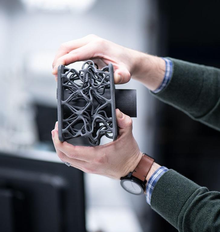
As they say, everything ingenious is simple.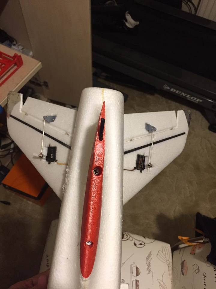 And Divergent 3D made us convinced of this. The 3D printing of the chassis is based on the use of aluminum connectors in a carbon fiber structure. Such elements are both extremely light and incredibly flexible, which is important in the automotive industry. In total, this system makes it possible to manufacture a chassis weighing 90% of average analogues.
The platform was called "Node" and managed to conquer a number of major car manufacturers. Divergent 3D printed chassis has several interesting features. First, it radically transforms the very process of car production and completely changes the focus points. This system reduces the negative impact on the environment, which is what many are now striving for.
In addition, the methodology enables the design and development of next generation lightweight, high performance components. In fact, the cars of the future will be built on such a system. Also, 3D printing of the chassis gives immense possibilities in the design and customization of custom vehicle components and prototyping.