3D print knob
Knob best 3D printing models・Cults
Giulietta JDM shifter adapter
Free
Abon Garden fan knob
Free
Spare kitchen knob.
€2.71
Noob Knob
Free
Noob Knob 2
Free
Pot Lid Handle
Free
MadMax_shifter_knob
Free
Garza Extruder Knob for Ender 3
Free
WOLF GOATEE LOGO
€1.62
Potentiometer support and knob
Free
18V Grinder control knob
Free
Rear seat knob H Civic CRX ED9
€3
D20 Elegoo Mars / Pro Cover Knob (or any printer)
Free
Ender 3 V2 Spiral Knob
Free
BRAIN DOOR KNOB
€3. -25% €2.48 31
Extruder Knob with Ender Dragon Logo
Free
Door knob insert shims
Free
Lamp Knob
Free
YAK - yet another knob (M5)
Free
Imitation cast iron steering wheel handle
Free
Sliding Door Lock
Free
Switch Knob
€0.50
Switch Knob
€0.50
Switch Knob
€0.50
Switch Knob
€0.50
Switch Knob
€0. 50
50
Switch Knob
€0.95
Nissan 350Z gear knob
€1.72
Ender 3 Punisher Knob
€1.41
Lamp Replacement Knob
Free
BMW E36 shift knob adapter
€3.21
gear shift alfa romeo gulietta
€2
Peugeot 205 shift knob
Free
Renault Clio 3 shift knob
Free
D&D Ampersand Extruder Gear Knob
Free
Ender 3 V2 Y axis belt tensioner replacement
Free
Makers knob
€4.95
Vintage Doorknob 3D Model
€11.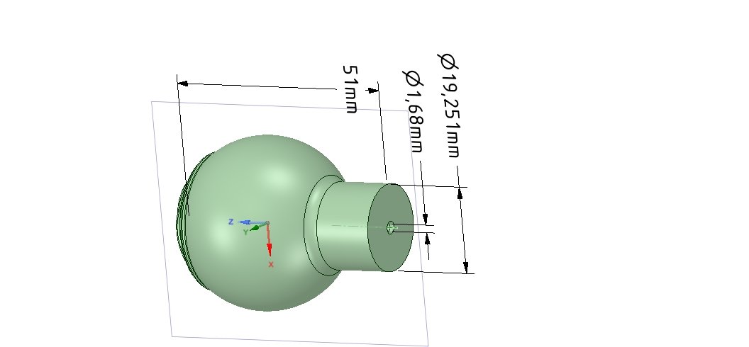 46
46
LEGO Head Encoder Knob
Free
SV-06 Control Knob
Free
Knob
Free
CR10 S CR6 SE CR20 Ender 3 5 Pro Bowden Extruder Revolver Knob
€1.49
Handle knob for frying pan glass cover
€1
Puxador afogador Volkswagen - Knob handle for gol
€2.72
Gear shift button renault megane 3
€7
Cabinet drawer handle and pull N006 miniset 3D print model
€2.82
Lever door handle lock
Free
Rocket Ship Extruder Knob for Ender 3 Pro
Free
Knobs and 3D Printing
Shapeways
I got into 3D printing very late in this project, so not much of it was designed or built with 3D printing in mind.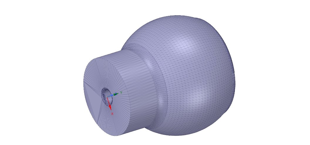
My first foray into using 3D printed parts was when I ordered some A-10C Knobs from a Shapeways store called A-10C Warthog Supplies made by ED forums user Deadman.
Shapeways is an online 3D printing service that is reasonably priced, and uses very high end printers that will give near perfect results. You can select multiple different materials, including metals. Anyone up for a $6000 USD solid gold knob in their cockpit? - Shapeways can do it.
I purchased only two of these 'Arrow Knobs' in 'White Versitile Plastic' to start off with and I was very impressed with what I received.
I eventually made more orders and ended up with:
- 6X Channel Select for the UHF
- 1X Volume Knob for the UHF
- 2X Main Preset Knob 164 for the UHF
- 2X Knob UHF1
- 2X Knob Lighting 2
- 1X TT155 (Translucent) for the EGI
- 1X TT158 (Translucent) for the CDU
- 1X TACAN Selector
- 1X Arrow Knob trans
- 4X Select ARC186 for the VHF's
- 2X Chanel Select
- 1X Preset Channel Select Knob for the UHF
- 1X chanel select knob
They are great, and most of them above remain in my cockpit today.
I did however run into some setbacks when I installed them. They come with mounting holes sized for the real aircraft rotarys, which have a smaller shaft. This meant i had to drill them out to suit my cheap rotary switches or potentiometers.
Sounds pretty simple at the time, but even with a clamp and bench press drill, i found it very difficult to either get the hole perfectly centered, or to clamp it firmly in the press to drill the hole without damaging the knob.
Some failed and were unusable, but most made the cut.
I made another order, this time changing the material to translucent so I could backlight them.
Again, I was impressed with the stunning quality print, but had the same issue with drilling out the holes.
Here is a selection of A-10C knobs straight from shapeways. High quality prints that I simply can't match on my cheap Creality Ender 3.
Here is one of the Translucent 3D printed knobs from Shapeways before paint. They backlight perfectly.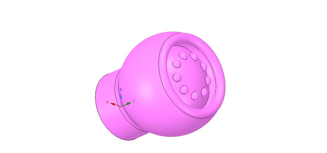
Two of the knobs being painted. The translucent knob gets a very light coat of white paint, then the arrow is masked before it gets a few coats of grey. I experimented using modelling clay to mask the arrows, but i could never get a good result. Peeling the glay peeled the paint as well. I ended up using normal masking tape for better results.
Knob finished and ready for mounting. Hard to see in this photo, but on the right it's on a flashlight and illuminating the arrow white.
Making my own Knobs
Shapeways was brilliant, but the cost start to get high when you factor in shipping to Australia. All up I spent around $300 AUD (OUCH) at Shapeways, and I realised I could just buy an entry level 3D printer for that amount.
Because I enjoy making things, and I like buying tools that require tinkering, I decided to get a Creality Ender 3.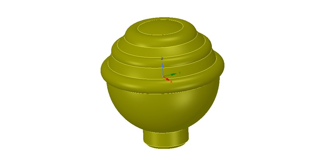 To read more about that, click here.
I first began by downloading some .STL files I found online here, and printing them out. I was impressed with what the Ender 3 could do, and with a little spray filler and paint they looked brilliant. FDM printers are limited by design, so they wont give you perfectly smooth items that the multi million dollar commercial printers that Shapeways likely use, but it was acceptable to me.
After printing those knobs, I again had issues with mounting them. For some reason I was unable to modify them in FreeCad to fit my needs, and I also found that they were slightly over-sized to fit my panels (or my panels were undersized)
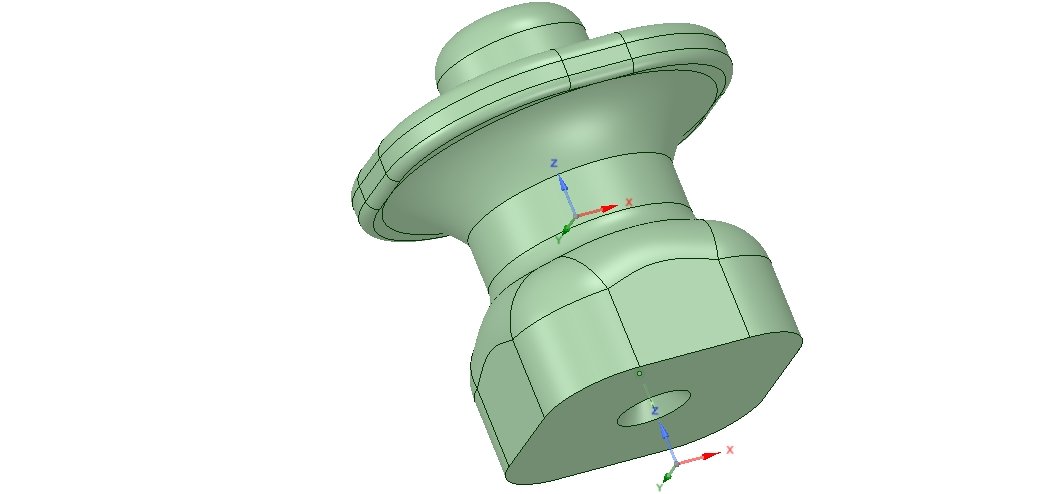
Rather than doing new panel tops to fit the knobs, I decided to design my own knobs from scratch in FreeCAD.
They are not exact replicas, as I had no real ones to compare to, and they are sized based of measurements I found online and some edited just to fit my panels. I also rounded all the dimensions to the nearest millimeter.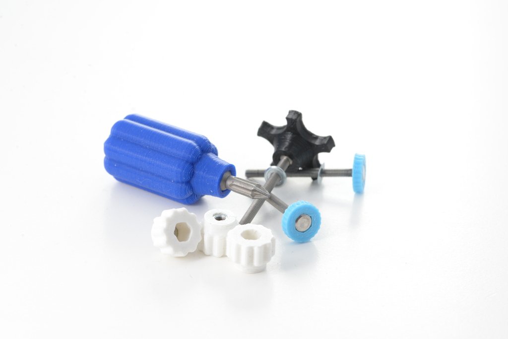 I have no experience in advanced use of FreeCad, so they were designed very basically using the Parts dashboard, just cutting and slicing with shapes.
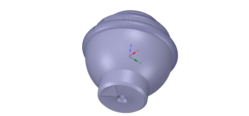
The first knob I designed in FreeCAD. Pretty basic. It's the mode knobs for an ARC-210.
Another knob i designed in FreeCAD. This one is the larger Volume Knob for the Intercom Panel.
And one of the Knobs for the Intercom Panel. Six off these required, and the dimensions are made up to fit my encoders and panel. They are also not backlit.
Here is one of the first Knobs I tried printing. Not my design, but it came out well. FDM printers wont make them perfectly, but with a few coats of spray filler and paint, I think they look pretty good.
Here is a bunch of knobs for the lighting panel, printed in clear filament to allow the arrows to be backlit.
Masked up and ready for paint. There ones I tried leaving the arrows clear, so no coat of white paint first. They backlit better, but i didnt like what they looked like when the console backlight was off so didnt end up using these ones.
A group of knobs I tried. None of these made the cut. You cans ee some had no white in the arrows, some had white, and the infil was different in the clear. I found the less infil backlit better, as long as i sliced it so there was no support directly behind the arrow. You can also see how i munt the, with a slot in it for fitting an M3 nut to keep the grub screw in place.
Two panels. The one n the right was for when i had no know backlighting, and the left one was the newer version with engrave sections to allow the backlight to illuminate the know. I also added a few more LEDs under that section to make it brighter.
Here was when i realised I can Laser Engrave things that I 3D print! This came out much better than trying the 3D print them with the text inset, then hand painting the text. I printed them in white, painted black and engraved the text, just like a panel.
Knobs weather up with a little dry brusing and ready for install. The dry brushing makes them look weathered, and hides the error in the print.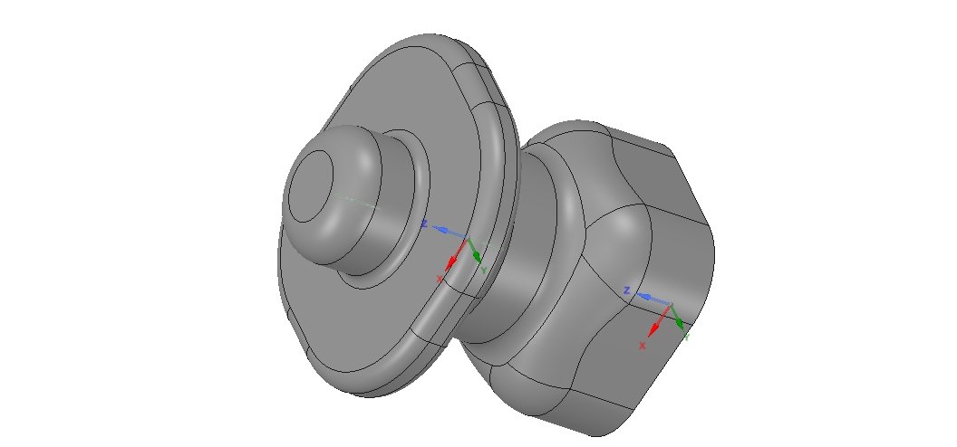 In fact, errors in the print actually make them lok like they are old and used!
The Console Corners
One of the panels I had a lot of problems designing was the angled sections of console on the top left and right of the side consoles, that hold the seat and canopy panels, and the canopy jettison and emergency brake handles.
I had tried making them from pieces of laser cut acrylic, using cardboard templates, however I never liked the result. I ended up giving up and just designed some simple flat panels to go in the corners, with the plan to revisit this and make it more realistic in the future.
Once I got my Ender 3, and became slightly proficient in FreeCAD, I decided to give them another go.
These were my first large prints on the printer for the cockpit, and I am happy with the result.
Once the console corners were complete I needed to do the handles for the emergency brake and canopy jettison.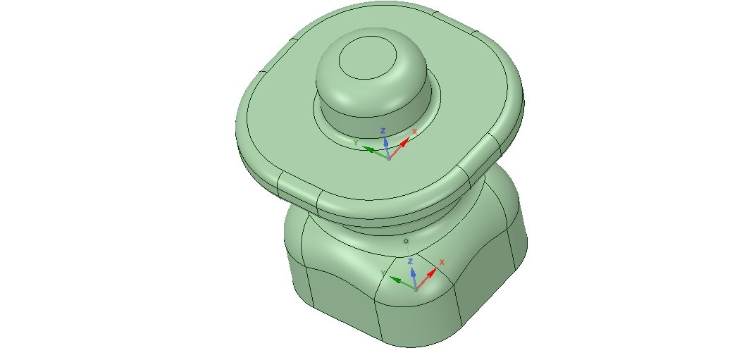 The mechanism is nothing fancy, it is just 10mm diameter aluminum tube, that pulls outwards to hit a microswitch inside. The real canopy jettison handle has a physical stop button that is required to be pushed in to allow the handle to be pulled out. I did not include this mechanism, instead deciding to put a simple electronic push button on the end of it. The canopy wont jettison in game, unless i pull the handle while pushing that button in. I also drilled a hole in the button on the bench drill to allow a remove before flight pin to slide in.
Here is the temporary design of the corner panels, before I 3D printed more realitic designs. The emergency handles were just buttons and switches.
The design in FreeCAD. The yellow section is laser cut acrylic, and the two other parts bolt on. I did this to avoid wasting 3D printing filimant, and my Ender 3 bed is two small to print the entire thing as one unit. I only designed one, then just mirrored it in Cura to print both sides.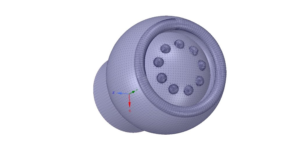
Printed upside down to minimise support material.
Both sides printed, filled and sanded and ready for paint.
Both sides painted and ready for install. The boarding ladder cover is the lid from a car cigarette lighter plug. The canopy jettison handle was an early prototype- way to thick.
And the canopy jettison handle design in FreeCAD. Free to download in the download section!
Heads Up Display Assembly
The HUD is a design I made from scratch, based on photos of the real thing, however using drastic artistic licence and blatently guessing the dimensions.
It is non functional and only for looks. I made it non functional for a few reasons:
- My PC has no more video outputs, so i cant export the HUD display. I'm using three for projectors and one for the MIP LCD. There is no way to get another monitor connected, while still being able to warp the outside view on the projectors using Nvidia Surround and the Immersive Display PRO software.
 You would need multiple PC's and GPU's to run anymore, and that is not a path I'm willing to take.
 - Combiner glass and LCD screens need very precise alignment, which would likley require a full rebuild of my MIP design.
- Making a HUD visible in the glass would be relatively easy, however aligning it with the outside view on the projectors perfectly enough for accurate BRRTTT, while being able to focus on both the hud and a projector on a surface not far behind it would be a large undertaking in itself.
- The costs involved would be very large, for not much percieved gain. The HUD on the projection surface looks fine and when aligned with the fake HUD from the seating position it feels real!
I also 3D printed a more realistic looking case for my UFC, as well as a faux HUD camera unit.
The indexers are the same F-16C style ones i made earlier, and I made up some brackets so I could mount them F/A-18 style on either side of the HUD glass frame, slightly angled towards the pilot.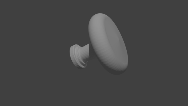 This is because in the A-10C they are mounted on the canopy frame, and I dont have one of those!
3D printed the HUD frame in two sections as the complete thing wont fit on the Ender 3 small bed. No supports required.
Here is the first prototype of the UFC case. The printers bed is two small,m so printed in two parts and glued together.
Trial fitting everything before paint. I printed in red and white because its the only filimant I had at the time, but after paint they looked great.
Another view. You can see the join where the two parts of the UFC case combine. I connect them wityh a solvent cement that melts the plastic and welds them together, so after glue they are as strong as a sinlge piece. The lower section of the HUD frame is just a hole, however i will later 3D print some more detail so it looks like a proper combiner.
The HUD and UFC case glued, filled and ready for paint. I sprayed them with an Auto Body Spray filler, then samd them. It completly hides the joint, and the 3D printing marks.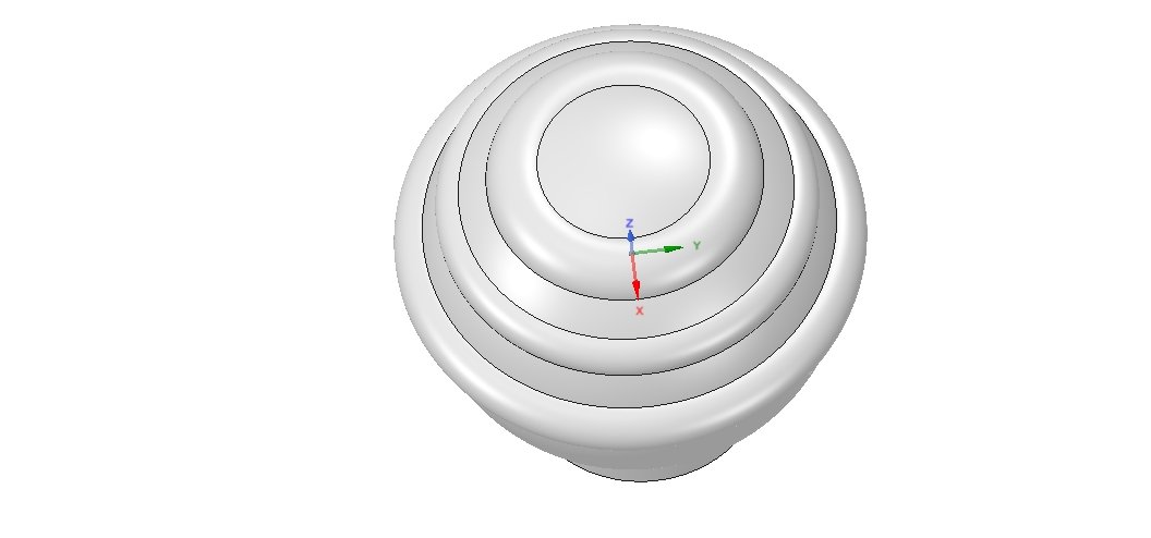 Looks like a solid cast unit after paint!
Painted and fitted. The Decals I made up in CorelDRAW, based on photos of the real thing. Printed on a normal inkjet printer on some packing labels. Not perfect buy it does the job!
Entire thing complete and fitted. Only thing missing in these photos is the clear 3mm acrylic I used for glass in the frame.
Another view. The cheap military style connectors will get some fake cabling added later on to make them look like the real jet.
Side view showing the box I added to the rear of the MIP to extend the glarehild and mount the HUD.
All it needs is the Occy Strap!
Centre Pedastal Handles
This is one of the latest additions to the cockpit. The original plans had these cut in the actual centre pedestal, but i removed them because i wanted to have them as seperate units, and i never really needed them so they were the last thing I did. I actually realiesd i did need them, after I copped a SAM in the left engine, lost hyrdaulics and couldnt get the gear down...
The mechanism is the same as the emergency brake and canopoy jettison handles above, simple aluminum tube with a bolt that activates a micro switch. Both handles were designed in FreeCad. The covers are one of the largest items i have printed, the exact size of the Ender 3 bed.
Decals were done recently on my vinyl cutter- more to follow on that later on.
The basic design in FreeCAD. Entire thing is 3D printed. The push button is not an actualy lock like the real thing, just on it for looks.
Printing the handles.
Handle and mechanism printed and ready for assembly.
Covers on the printer.
Both handles mounted on the sides of the centre pedestal.
Other 3D Printed Details
There are other small details i have 3D printed for around the cockpit, just to have it look a little more realistic.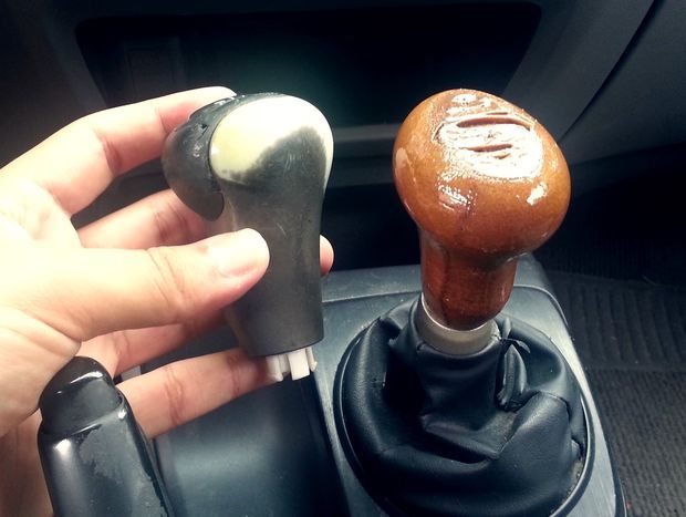
The Scorpion HMCD panel was one of the lastest additions to our DCS hawg. Its a simple panel, with a single 3 position toggles switch. The battery and plug covers were all 3D printed, based of the one in the game. They serve no purpose other thajn making it look good.
The completed panel with 3D printed details.
The VS1500 datat recorder does nothing in the game, and i made one only to make it look cool. The dead space inside i turned into a storage area. Designed in FreeCAD based of photos of the real thing.
The top panel and cooling fins are laser cut and glued acrylic. The latch and door are 3D printed in black and orange.
Door is designed to latch and work like the real thing.
I printed the box out of orange because its the filimant i had, but i actually ended up loving it as it makes it much easier to see anything inside.
Painted up and ready to mount. The connector is just one i had loose in my spare parts bin. No datat cartridge in here, just a storage area for random tools/bolts/thumb drives etc.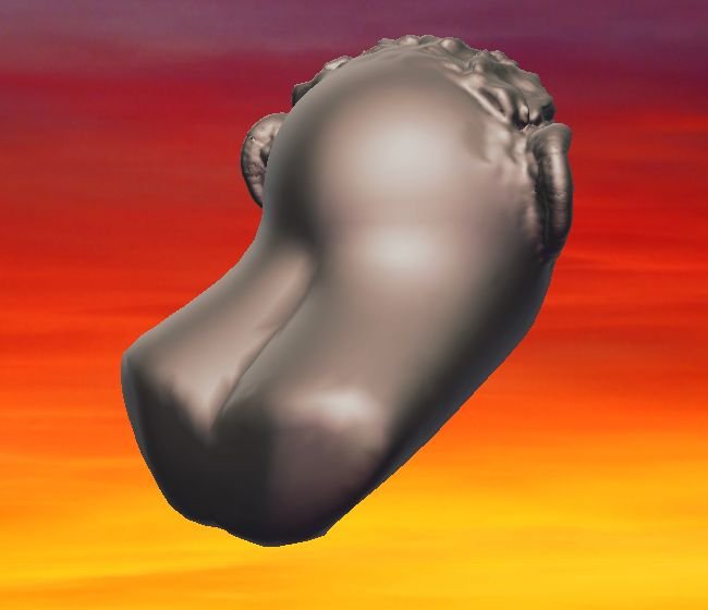 The entire lid is press fit and just lifts off.
Weather up and ready to fit.
I designed and 3D printed a whole bunch (100+) of these DZUS replicas that just press fit on top of the M5 bolts holding the panels in. After paint and some weathering they camne out pretty good!
The DZUS covers finished and mounted on the Radio Panels. It's a small detail, but it's better than looking at M5 bolt heads.
3D Pen
- 1 Description
- 2 History
- 3 Design
- 4 Materials
- 5 Application
- 6 Development
- 7 Interesting 3Dtoday blog posts about using 3D pens:
Description
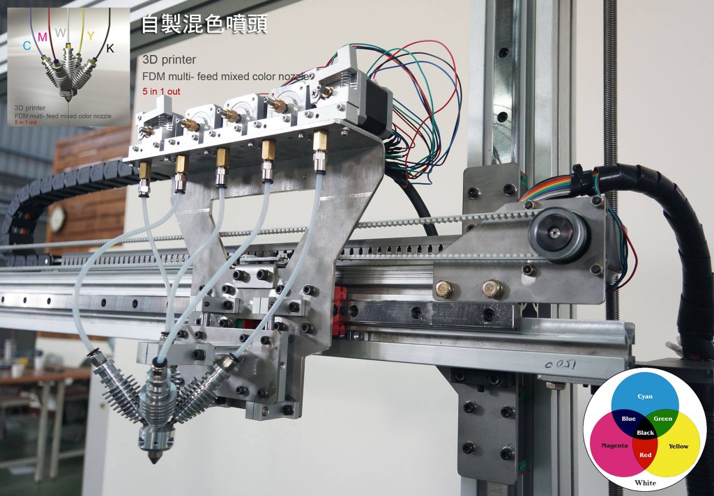
FDM printing is the logical evolution of CNC machines. The only fundamental difference was the use of a specialized nozzle (extruder) for melting and feeding plastic. By the same logic, hot glue guns, which are widespread in everyday life, have also been developed. The use of thermoplastics instead of thermoplastic adhesives allows devices like these, dubbed 3D pens, to be used as hand-held additive manufacturing devices. nine0022
Parts of the future model can be drawn on paper using templates and glued together
History
One of the latest developments is the Dim3W 3D pen
The pioneer of a new direction in the development of 3D printing was the pen from Wooodleworksr.
The team turned to Kickstarter to raise the funds needed to bring the project to life.
With a goal of raising $30,000, Wobbleworks had raised over $2 million by the end of the campaign, indicating high public interest. nine0022
Amid the success of 3Doodler, a competitive wave swept through. At the moment, the range of 3D pens includes actual 3Doodler clones like 3DYAYA or SwissPen, as well as more original designs including Dim3W and LIX.
The basic principle of operation of all these devices is the same, but there are some design features aimed at improving a fairly young concept.
Construction
In essence, a 3D pen is nothing more than a manual extruder. The user himself acts as the CNC of the machine. nine0022
3Doodler disassembly. The nozzle at the bottom and the pull mechanism in the middle of the handle are clearly visible. and heating element.
Since almost all software functions of 3D printers are performed by the user, 3D pens do not require a connection to a computer or the creation of digital models. Only a power supply is required - as a rule, conventional power supplies with a 12V voltage converter are used. nine0022
As with FDM printers, it takes a few minutes for the nozzle to heat up, after which the pen is ready to print. The supply of material is carried out by pressing the corresponding button. Some models, such as the Dim3W, are equipped with a print speed control.
Also available with reversible pull mechanism. This feature allows you to quickly remove the plastic filament from the pen and replace it with a different color material.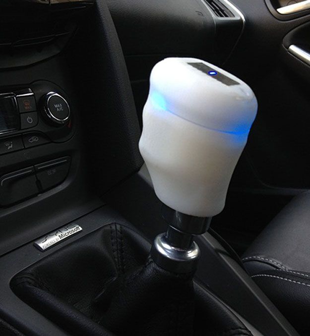
Materials
3Doodler complete with colorful ABS plastic packs
Two of the most popular plastics in FDM 3D printing are currently used as materials for 3D pens - ABS plastic and organic, biodegradable polylactide (PLA plastic). Theoretically, it is possible to use other materials - polycarbonate, nylon, etc. At the same time, existing models do not provide the ability to accurately adjust the nozzle temperature, which is important when switching to other materials. Temperature characteristics are embedded in the firmware. In the future, we can expect more variety in the range of materials and the ability to fine-tune the temperature if there is a corresponding demand. nine0022
Like full-fledged FDM printers, 3D pens use thermoplastic filaments with a diameter of 1.75 or 3mm. For ease of use with the pen, the threads are usually supplied as scraps rather than spools, but it is ultimately up to the user to choose.
Applications
Similar voids formed during plastic delamination due to uneven cooling can be filled with a 3D pen
3D pens are positioned as a means for creative work, three-dimensional drawing. Although devices can indeed fulfill such a role, creating more or less decent-looking models requires serious skill. nine0022
However, initially 3D pens were conceived for a completely different purpose, similar to the purpose of their ancestors - hot glue guns. It's about repairs. The fact is that some types of plastics used in FDM 3D printing (for example, the very popular ABS plastic) have a high degree of shrinkage and a tendency to deform during uneven cooling. All this often leads to cracking of the manufactured models. 3D pens were supposed to be a tool for manually repairing printed models. These devices allow you to fill in missing layers or faults. nine0022
Particularly good results can be achieved with careful treatment of cracks with acetone, which dissolves ABS plastic.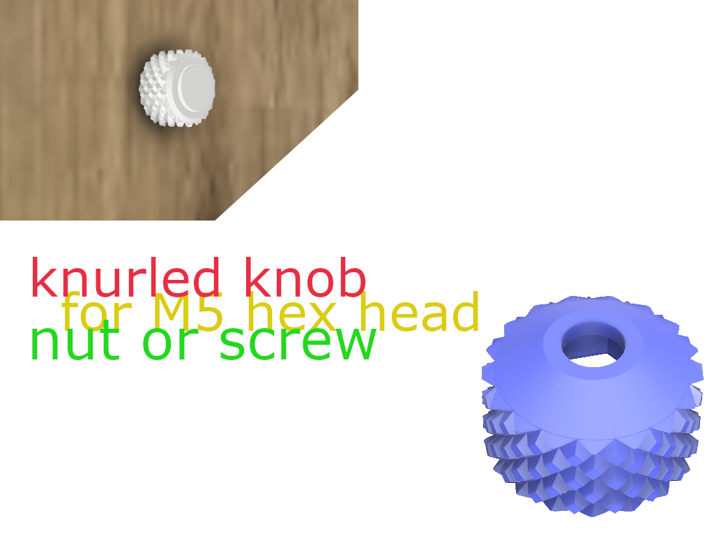 The surface softened in this way will adhere well to freshly applied plastic with a 3D pen.
3D pens allow you to draw in the air instead of paper
The surface of the repaired area can be leveled by sanding and gently working with the same acetone. Similarly, household products can be repaired - many of them are made from the same ABS plastic that has become widespread in the industry. nine0022
As for artistic applications, 3D pens will appeal to those who love to draw and want to move from 2D sketches to 3D physical models.
The main difficulty lies in purely human limitations - any unwanted hand movement will affect the quality of the model, especially when drawing the model "in the air".
One interesting way to improve the quality was to divide the models into component parts, using sketches on paper as templates. Finished parts are simply glued together. nine0022
BioPen allows surgeons to "paint over" damaged areas of bone or cartilage tissue, contributing to its restoration
This method is quite possible to make a good reproduction of the Eiffel Tower.
Of course, the method is applicable only when creating parts of models with relatively flat surfaces.
The possibility of using a variety of 3D pens in medicine is very promising.
Devices called "bio-pens" (BioPen) are being tested as tools for applying live cell layers mixed with biopolymers that act as support matrices and contain essential nutrients. nine0022
The original 3D BioPen was developed by Australian scientists at ASEC and is designed to repair cartilage and bone tissue.
During surgery, PioPen allows clinicians to “paint over” damaged areas of bone or cartilage, stimulating the recovery process.
Development
CreoPop - the next step in the development of 3D pens
Following the FDM technology, photopolymer 3D printing has also undergone adaptation for "manual" use. The CreoPop project proposes an innovative 3D pen design based on the extrusion of a liquid photopolymer resin that cures when exposed to a UV light. Unlike FDM handles, such a device does not pose a risk of burns - there are no hot elements in the design. In addition, photopolymer resins are known for a wide range of physical properties, ranging from solid materials to rubbery and even magnetic ones. The cost of such devices will be quite low, at the level of FDM 3D pens, but the cost of consumables will make this 3D drawing method somewhat more expensive. nine0022
Interesting 3Dtoday blog posts about using 3D pens:
- New Year symbol of the year with a 3d pen
- 3Doodler for small and big creative "Ninjas"
Go to the main page of the Encyclopedia of 3D printing
3D-pen for 3D-printer, fixing blotted print / Sudo Null IT News
Almost everyone has heard about 3D-pens. Many have tried them, many have them. So, perhaps, this gadget will surprise no one. And, probably, if there is a 3D printer at home, then the pen against its background will look very funny.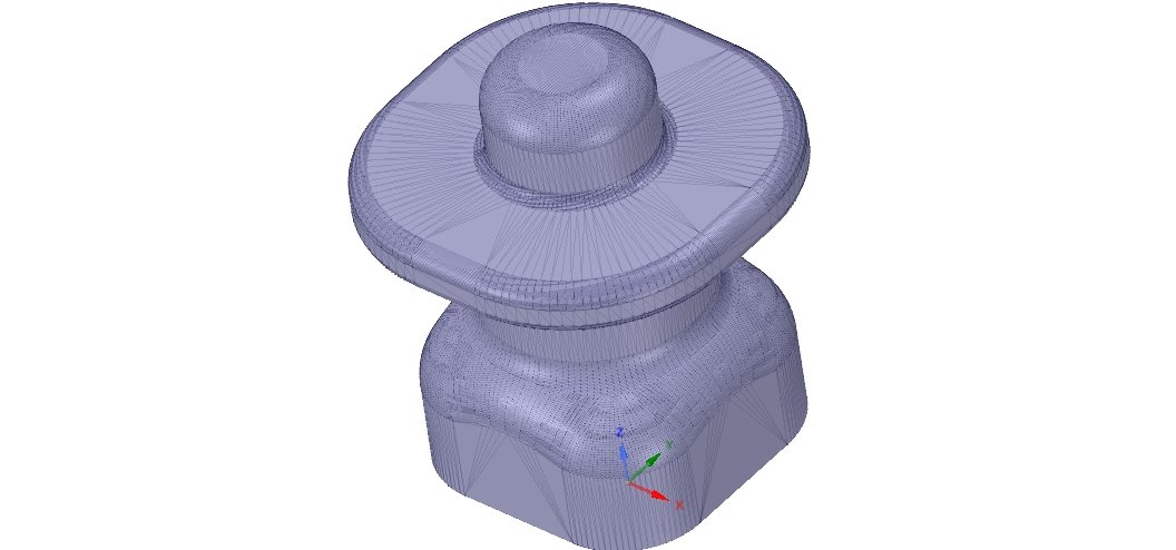 But... Do not rush, a 3D pen can become an indispensable assistant and a very handy tool for any maker. Now, using my example, I will show how easy it is to save a three-dimensional model that took 41 hours to print using a 3D pen. nine0022
Let's start by inspecting the gadget.
Everything is standard, the box contains instructions, power supply and the pen itself.
Power supply cable length 1.4 m, should be enough for most outlets near tables.
12 volt, 3 amp power supply.
It easily gives out the declared volts at idle, I didn’t measure the current, sorry. Let's go straight to the test.
Handle like a handle. Of the interesting - this is the specified nozzle diameter - 0.7 mm. A big plus for me personally is that the pen is omnivorous. You can print both PLA and ABS. There is also a manual temperature control.
Mode selection is intuitive. You just need to press the buttons on the sides of the screen.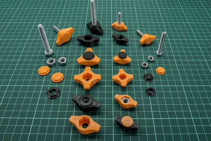
Next, press the feed button, you can release it once. Heating starts. Heats up quickly, faster than a 3D printer. nine0022
When the desired temperature is reached, the indicator to the left of the screen changes from red to green.
In addition to the temperature adjustment, the handle has an adjustment for plastic feed (speed).
On the other side of the feed adjustment there are 2 buttons - “squeeze out” and “pull out”.
Filled for the first test with a piece of plastic left over from the last print.
On the first delivery, you can see that there was already some plastic in the nozzle. This is good, since the handle was really checked. Some printer manufacturers supply them with a printed figure on the table, the user immediately sees that the device is working and prints as it should. nine0022
I had a test plastic right away for a reason, I refilled transparent SBS, it is quite soft and often there are problems with it when printing on a printer.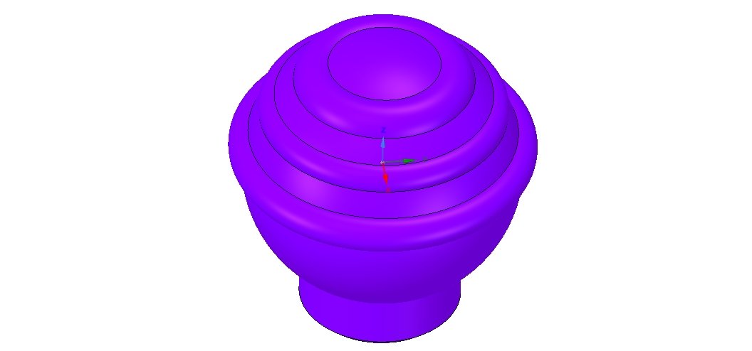 Here, everything immediately went briskly.
A small digression.
I was given a set of plastic along with the pen.
3D palette.
By the way, a very good addition to the 3D pen. In addition to conveniently located plastic in separate pockets, there is a compartment for storing a pen, as well as an envelope with sketches on tracing paper for easy creation of three-dimensional models. nine0022
Let's check the handle on a simple model first.
We take a tracing paper and draw glasses along the contour.
When the plastic has cooled, it can be easily removed from the tracing paper. We're filming.
Draw the second bow.
Next, melt the temples to the glasses.
PLA plastic is very pleasant to work with, easy to soften and stick to each other. But there is one drawback, it should not be overheated, it becomes too fluid, but more on that later.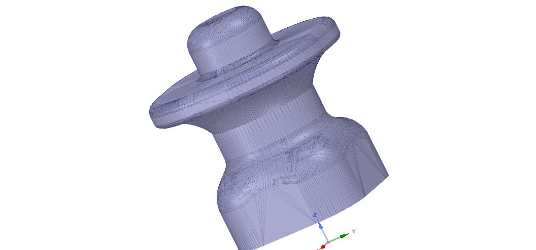 nine0022
Glasses are ready.
Now let's get down to business. I printed a Pinky monster figurine from DOOM 3. Printing did not work right away, the model is very complex with spikes and other details sticking out in all directions. I printed both in 2 extruders with supports from HIPS, and with supports generated in MeshMixer. But when moving to the beginning of the hands, something always fell off and I had to stop printing. Perhaps the plastic is to blame, it is almost a year old and it was stored without a package and a box, just like that. nine0022
In general, for the third time I combined printing methods and added supports from HIPS plastic to the model with supports from MeshMixer. In the middle of printing, I saw that my hands were torn off again, but I spat and finished printing to the end, deciding to simply glue the damaged parts.
The details have been reprinted and now with the help of a 3D pen I can easily glue them to the main model.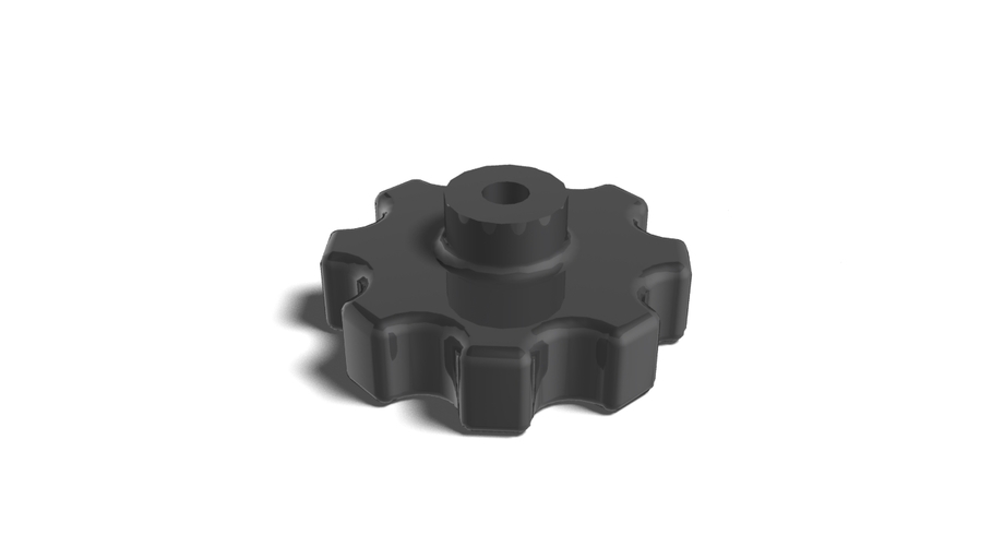
With such a seam, glued parts are obtained, but firmly. And the protruding excess plastic can be ground off or cut off with a knife after treatment with dichloromethane. nine0022
Saw off the muzzle.
And glue a new, high-quality one.
This is a darned creation of Frankenstein.
Here you can see the comparison of the quality of the old and new muzzle.
Let's move on to the hands. It’s more difficult here, in some places it turned out to be a big gap.
But, in principle, the handle easily copes with wide gaps.
It remains only to process the seams.
I didn't sand or sharpen them dry. I decided to treat the entire model with methylene chloride, it dissolves both PLA and ABS equally well.
The seams have become smoother, but most importantly, the top layer of plastic has become soft and can be easily cut with a knife, like plasticine.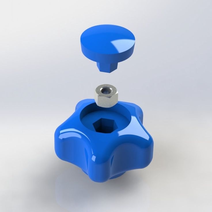 Align all the seams, cutting off the excess, and once again go through the brush with DCM.
And here is the result:
Finally, let's look inside the 3D pen. nine0022
Remove the black tip and unscrew one single screw.
Here you can see a ceramic nozzle with a heater and a thermistor, a short bowden tube and an extruder on a simple brushed motor. The feed is controlled by the rotation speed of the motor shaft. On the motor there is a small brass gear pushing through plastic, on the other hand, all this is pressed by a small bearing with a flat side. In general, everything is very simple, like Kalash. Yes, and remember, I wrote about the fact that you should not overheat PLA plastic. In the disassembled photo, it is noticeable that there is something red on the back of the heater, where the tube enters it. It's just PLA plastic, I painted it a little in the heating mode for ABS, and it became so liquid that it went in the opposite direction.