3D print holes in walls
troubleshooting - Gaps/Holes in the 3D Print walls
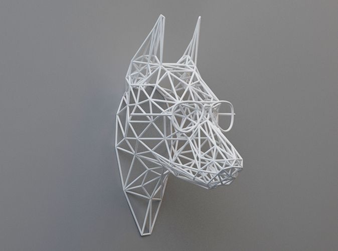
I'm new to 3D printing, I bought an Ender 5 Pro just recently. Trying to print with 1.75 mm PLA, but the results are very bad, unfortunately. When I got after bed leveling I got a decent result from the demo dog and started to print small things, where the quality was acceptable. Then I tried to switch to bigger items, but the printing failed half-way due to not enough adhesion.
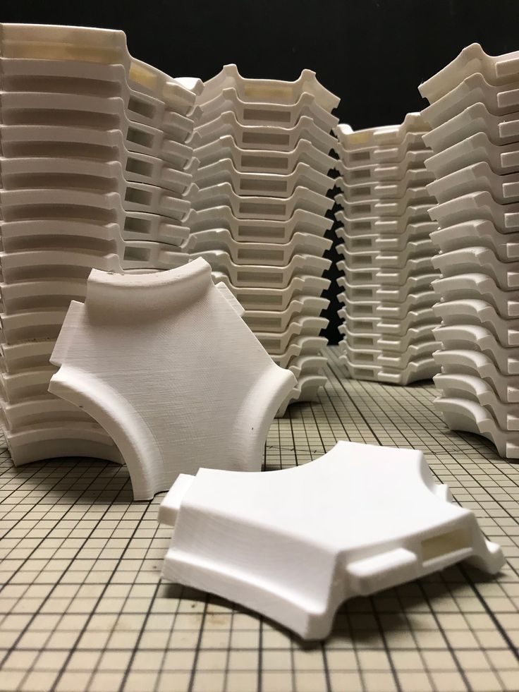
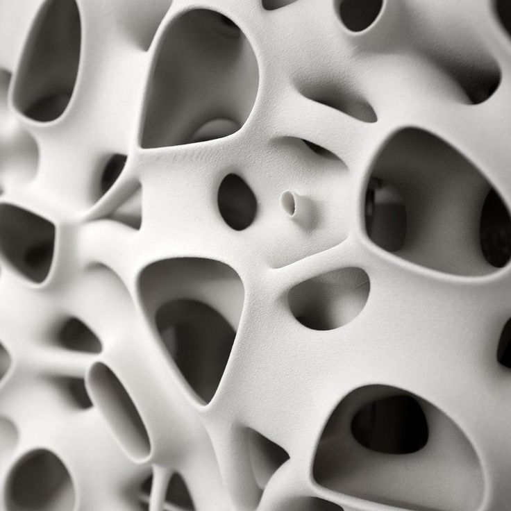
There were other quality problems too with this print, and you can already see that in the walls there are holes:
I did another round of bed leveling and Z alignment to make sure the adhesion is good and a test print came out quite fine in all corners and the center. The one layer rectangles and not perfect, in some places the lines separate, but they are mostly fine. But now I have a different problem: all the prints are very messy, less clear, they are not as strong as before and also there are big holes now in the walls. The same statue base (as I had to stop after getting messy earlier) looks like this now:
Another try failed after a few hours (like printing stopped and was printing nothing in the air), but also there is the holes/gaps problem even more visible:
Finally as a test I printed an object with the same G-code as previously used and the result is much different. The object on the left is the new one. It is weak, you can feel by pressing that the walls are not solid, they bend. The rectangle "eyes" are also not clear:
There is a difference though, I changed the extruder's nozzle between, the new one was also in the Ender package, it is also 0.4 mm as the original should have been, I changed to try with a new one.
Because of the last test with the same gcode, different result, I think the problem might be in hardware adjustment as well, not only software. Anyone has an idea what I'm doing wrong?
EDIT 1: after calibrating the extraction amount and reducing the print temperature from 200 C to 190 C, now I get the below result. The values used:
- Bed temperature: 65 C initial, 60 C for the rest
- Print temperature: 200 C initial, 190 later
- Print speed: 80 mm/s
- Wall speed: 40 mm/s
- Retraction: 10 mm
- Retraction speed: 80 mm
- Wall thickness: 0.8mm
- Layer height: 0.
 2 mm
2 mm - Initial layer: 0.2 mm
- Line width: 0.4 mm
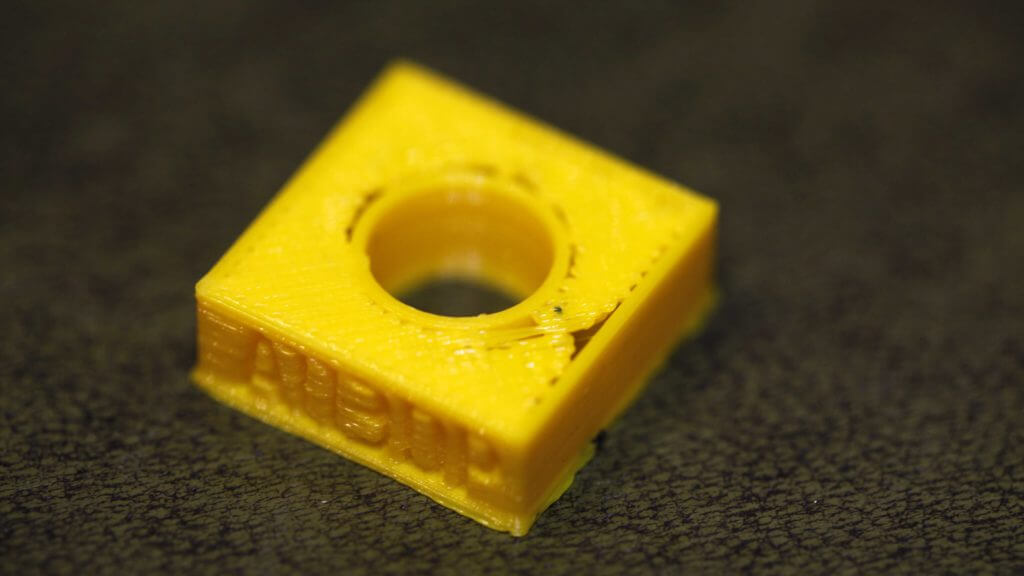
EDIT 2: Based on the comments, some changes were made and here are the results. XYZ cube,
- print speed reduced to 60 mm
- layer height 0.12 mm
- Z Seam Alignment is Sharpest Corner
- Infill density 30 %
- Retraction distance 8 mm
- Retraction speed 40 mm
It looks good, the layers are visible though, some ghosting right to X and Y. The sizes are not correct though: X = 20.07 mm, Y = 20.03 mm, Z = 19.84 mm
Are X/Y acceptable? What should I do with Z, increase steps/mm ?
Finally here is the 3D benchy too, although looks mostly fine, there are some bumps in the walls and small strings in open areas. This was printed earlier and with different settings though:
- Layer Width 0.2 mm
- Print speed 80 mm
- Retraction 10 mm
- Retraction speed 80 mm
- Z Seam Alignment is set to Random
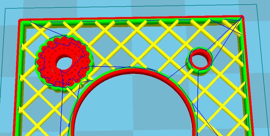
EDIT 3 I tried now to print the PolyPearl, that has thin curving lines. 2$ (default is 500)
The model sticks well to the glass plate even without glue or hair spray, maybe a little too well. I see some problems though, not sure how normal they are:
- outside area of first layer is not nice
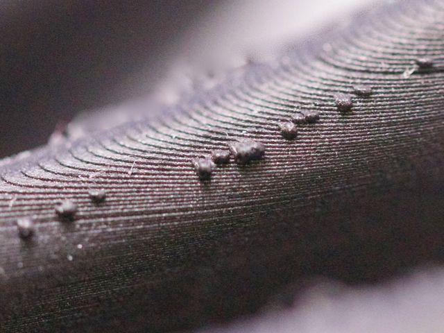
- there is some oozing, thing lines on the surface and between the columns
- the top end of the tower is somewhat messy and there is a horizontal line attached to it (sure, can be removed easily)
- the bottom is very smooth, I can see the glass' texture (the Creality glass top is textured) and the texture of the very first failed print, when I didn't take into account the extra height of the glass after leveling, and the print head hit it hard and the nozzle got completely damaged. Beginner's fault.
Here are the images: https://photos.app.goo.gl/ZfuMFFedL171eLeM7
Are this problems normal/acceptable?
ultimaker cura - How to fix wall separation in 3D prints (gaps in between wall perimeters)?
Ask Question
Asked
Modified 3 years, 3 months ago
Viewed 41k times
$\begingroup$
The print is very solid except for the 4 walls.
From the top, I can slide a paper down to the bottom. This is ONLY between the walls, the rest of the print is solid. The filament is PLA 1.75 mm.
But the bottom is solid, no gaps.
I have checked the usual problems on Ultimaker troubleshooting photo gallery, but I can find anything similar.
Any advice to fix this would be very welcome.
Print settings:
- print-quality
- ultimaker-cura
- 3d-design
$\endgroup$
2
$\begingroup$
To fix this, I had results with the following way:
- Change your extrusion width from being equal to your nozzle size (0.4 mm) to slightly larger (I use 0.45 mm). That way you better combat the shrinking of the filament.
- Having the
Print thin wallssetting activated to force the printer to print intermediary walls if there are areas where less than the prescribed wall thickness for a single wall fills in spaces that are as a result of the wider outer walls left. The result for a 1.2 mm wall, the central part is a 0.3 mm zigzag.
 - Lower the extrusion temperature a tad as hotter filament shrinks more on cooling! For PLA about 200 °C is my sweet spot.
Additionally, there are extra steps that could be taken: * Finally, you could play around a little with the extrusion multiplier to try to get rid of the tiny bit of under extrusion you have. * Calibration could help too.
$\endgroup$
6
$\begingroup$
Now that print settings are shared we can see that this problem is not related to too fast printing (only 20 mm/s) or too low print temperature (210 °C should get PLA fluid enough). To explain this, a low temperature and too fast printing cause under-extruded lines.
There are 2 other causes that might be worth investigating:
- Under-extrusion. From the top layers one can see that there may be insufficient material printed.
 Calibration of the extruder helps in this respect.
 - Inaccurate positioning. This may for instance be caused by loose belts or a mechanical defect.
$\endgroup$
$\begingroup$
I've experienced this too, especially with flex modified PLA filament. For that, fixing underextrusion and increasing temperature made it go away. Sadly Cura has no option to overlap walls slightly (if printed in the right order, this could be done without affecting dimensional accuracy) except possibly the outer one, so you really have to get extrusion rate calibrated right or this will happen.
$\endgroup$
$\begingroup$
Look for the horizontal expansion setting in Cura. By default it should be zero. The description includes this:
Positive values can help compensate for too big holes.
The "holes" here includes these gaps. You can set it to something very small (ie: .01 or .03, probably no more than .05) and that will likely be enough to get it to fill in those gaps.
Unfortunately, I only have a little direct personal experience with this setting, hence the probably/likely weasel words, and I can't give much real guidance on exactly how big or small you can go with this.
$\endgroup$
3
(There is a solution) Gaps/holes in 3D printing walls
I am new to 3D printing, I recently bought an Ender 5 Pro. I'm trying to print with 1.75mm PLA but the results are very poor unfortunately. When I got there after leveling the table, I got a decent result from the display dog and started printing small things where the quality was acceptable. I then tried to switch to larger items, but the print failed halfway through due to insufficient adhesion.
There were other quality issues with this print and you can already see that there are holes in the walls:
I did another round of table alignment and Z alignment to make sure the adhesion was good and the test print came out pretty good in all corners and center. Single-layer rectangles are not perfect, the lines split in some places, but mostly they are small. But now I have a different problem: all the prints are very dirty, less clear, they are not as strong as before, and there are also large holes in the walls. The same base of the statue (how I had to stop after getting dirty before) looks like this now:
Another attempt failed after a few hours (e.g. printing stopped and printed nothing in the air), but there are also problems with holes/gaps even more noticeable:
Finally, as a test, I printed an object with the same G-code as before, and the result is very different. The object on the left is the new one. It is weak, you can feel by pressing that the walls are not solid, they bend. The "eye" rectangle is also not clear:
There is a difference though, I changed the extruder nozzle between, the new one was also in the Ender package, it is also 0.4mm, as the original should have been, I changed to try with the new one.
Due to the last test with the same gcode and a different result, I think the problem may be in the hardware setting as well, not just in the software. Does anyone know what I'm doing wrong?
EDIT 1 : after calibrating the ejection amount and lowering the print temperature from 200 C to 190 C, now I get the following result. Used values:
- Table temperature: 65 C initial, 60 C for others
- Printing temperature: 200 C initial, 190 later
- Print speed: 80 mm/s
- Wall speed: 40 mm/s
- Retraction: 10 mm
- Retraction speed: 80 mm
- Wall thickness: 0.8 mm
- Layer height: 0.2 mm
- Starting layer: 0.2 mm
- Line width: 0.
 4 mm
4 mm
EDIT 2 : Based on the comments, some changes have been made and here are the results. Cube XYZ,
- print speed reduced to 60 mm
- layer height 0.12 mm
- Seam alignment Z is the sharpest corner
- Fill density 30%
- Retraction distance 8 mm
- Retraction speed 40 mm
It looks good, although the layers are visible, some ghosts right on X and Y. Dimensions not correct though: X=20.07mm, Y=20.03mm, Z=19.84 mm
Are X/Y allowed? What to do with Z, increase steps/mm ?
Finally, here's the 3D benchy too, although it looks mostly ok, there are some bumps in the walls and small strings in the exposed areas. This has been printed previously and with different settings though:
- Layer Width 0.2mm
- Print speed 80 mm
- Retraction 10 mm
- Retraction speed 80 mm
- Z Seam alignment set randomly
EDIT 3 I tried now to print a polypearl which has thin curved lines. The first attempt failed after 2 hours, a pen appeared on the nozzle, which ruined the print. It was a print from 190 p. I gave it another try and printed with 200 C and surprisingly it completed the job. See below photos, here are my settings for it (changes for Cura 4.6.0 default Super Quality):
- Layer Height: 0.08mm
- Initial layer height: 0.12 mm 92$ (default 500)
- Print jerk: 8 mm/s (default 10)
- Retraction distance: 8 mm
- Retraction speed: 40 mm/s
The model adheres well to the glass plate even without glue or hairspray, maybe a little too well. I see some problems, although I'm not sure how normal they are:
- the outer area of the first layer is not very pleasant
- there are some oozing, strange lines on the surface and between the columns
- The top end of the turret is somewhat dirty and has a horizontal line attached to it (of course, it can be easily removed).
- the bottom is very smooth, I can see the texture of the glass (the top of the Creality glass is textured) and the texture of the very first failed print when I didn't take into account the extra height of the glass after leveling and the print head hit it hard and the nozzle was completely damaged.
 Rookie mistake.
These images are here: https://photos.app.goo.gl/ZfuMFFedL171eLeM7
Are these problems normal/acceptable?
▲ 4
Let's see what errors I'm seeing (accumulated from what I've commented):
The legs seem to be very weak. This can be either a clogged nozzle, printing too fast, or too low a temperature, or too low a pressure (for example, an incorrectly calibrated extruder). Try cleaning or a fresh nozzle, another parameter game can wait after you fix the next big problem.
To fix under extrusion if it persists after fixing the chime, experiment with the following settings:
- Check the mechanical system. Make sure the extruder
- has no defects. I saw a lot of underextrusions when my extruder arm broke. The gear turned, but no longer pressed on the thread.
- presses the filament with the idler bearing well against the hob gear.
- is properly calibrated for physical parameters. Use the extrusion multiplier to account for different materials.

- Temperature. If the extrusion is not going well, increase it by a factor of 5. The °C steps can help.
The dented cube shows this best: massive ringing occurs. This is the effect that occurs when the printer changes direction rapidly - the printhead cannot speed up and slow down indefinitely as it has momentum, and as a result oscillates around the new path a bit, like a sine ring. This creates a "ghost" of previous toolpath changes on the flat face, which is why I asked for the cube to be printed.
There are 2 software fixes to fix ghosting and ringing:
- Reduce the print speed.
- this comes at the cost of longer print times
- Improve your maximum acceleration and jerk
- Slightly lowering the maximum acceleration (from 500 mm/s2 to 1000 mm/s2) can significantly improve print quality with little to no effect on overall print time and keep print speeds high.
- Jerk is a derivative of acceleration; figuring out the two values that might be best for setting up a printer can be a lot of experimentation.
There is also a hardware way to reduce it in many designs by shaving weight off moving parts or strengthening the design:
- Get a lighter printhead
- removal of unnecessary add-ons
- replacement for lighter print head design
- transition to Bowden design
- in CoreXY: use lighter rails
- Toughen the structure
- Adjust the carriage mount so that it compresses better
- replacement of bearings and bushings with bearings with tighter tolerances
- ties can significantly strengthen the structure of the portal and cube
This could come from any of several sources. In descending order of similarity:
- the first layer is not a multiple of the actual layers (eg 0.12 instead of 0.2 mm), resulting in a partial layer at the top of the cut. in the example given, this would result in a fixed negative error of of about 0.
 08 mm.
 - Incorrectly calibrated first layer. Depending on your alignment skills this can result in a fixed error of up to 0.1mm for a bad calibration up to 0.025mm for a really good calibration. This error can be either positive or negative.
- Z-axis inconsistencies due to misaligned lead screw, sticky lead screw, or insufficient Z-step motor voltage. Both tend to create a systematic error - as when printing a given percent loss of height. Such inconsistencies can be eliminated by solving the problem mentioned: first check the orthogonality, then carefully lubricate the screw with light machine oil (not WD40!), finally, increase the motor voltage a little. Only if your results are severely out of order, you should check if your steps/mm are set correctly. But I don't see the need for it.
, @ Trish
Fixing the 20 Most Common 3D Printing Problems
3DPrintStory 3D printing process Fixing the 20 Most Common 3D Printing Problems
3D printing allows you to create amazing models. But everyone faces unpleasant moments when even a simple model does not print well.
You've checked the model, making sure that many have already printed it and had no problems. What are you doing wrong?
This article has collected 20 of the most common 3D printing problems. We hope that the article will help you quickly identify the problem and find a solution for it. In addition, the article details the causes of problems during 3D printing, which will help you avoid them in the future.
Model tearing off
Problem description
At the base, the model rises up relative to the table (English - warping). In addition to the quality of the manufactured part, this problem can prevent the printing of tall parts that can finally fall off the table.
What causes this problem during 3D printing?
Part breakage is a very common problem due to the nature of the printable plastic. As the ABS or PLA plastic cools, it begins to make poor contact with the surface, so the "warping" effect occurs when the plastic cools too quickly.
Solve the problem: part is torn off
- Use a heated table. The simplest solution is to use a heated table slightly below the melting point of the plastic. If the temperature is set correctly, the first layer will be in firm contact with the table. Most often, the platform temperature is set in the program to generate the g code for the model. The recommended temperature is often indicated on plastic packaging.
- Use adhesive. If your model still wraps around the corners, apply some glue to the print bed.
- Try another table. Replace your print bed with a model that offers better adhesion. Manufacturers such as Lulzbot use PEI (Polyetherimide) surfaces. XYZPrinting add special tape to the printer box and that works great too (but they don't have heated tables). Zortrax 3D 3D printers solve the problem differently - with the help of small holes in the table.
- Level the print table.
 It may be worth calibrating the print platform. During calibration, make sure that the tip of the extruder is at a suitable, uniform height from the stage along its entire plane.
 - Reinforce contact. Increasing the contact between the model and the print bed is another easy way. Most 3D printing software has the ability to add additional layers to the base.
- Play around with the temperature. If none of the above work, try increasing the print bed temperature in 5-degree increments. Also pay attention to the operating modes of the coolers. Usually coolers start to work at full capacity when the model height is about 0.5 mm. Try increasing this height to 0.75mm so that the base layers have more time to cool naturally.
And finally, even if you have a heated table, applying a little glue is unlikely to hurt.
3D Printing Problem Checklist: Part 9 Tear Off0241
- Use a heated bed
- Add glue to the print bed
- Use a high-adhesion bed from quality manufacturers
- Calibrate the bed
- Add extra layers to the model base in your 3D printing software
- Play around with temperature and settings cooler
Elephant leg
Description of the problem
The base of the model is printed with a distinct indentation to the outside. It is called - “elephant's foot”
What causes this problem during 3D printing?
This undesirable effect is caused by the mass of the model itself, which presses on the first, insufficiently cooled layers. In particular, this problem occurs if you have a heated table.
Solve the problem: "Elephant's foot"
- Correct balance. In order to avoid this problem, it is necessary to properly cool the layers at the base of the model. The base layers must be able to support the mass of the part, but not overcool, so that the part does not start to come off the table. Finding the right balance can be tricky. Start by lowering the table temperature in 5 degree increments (within +/- 20 degrees from the recommended temperature). If your bottom and top layers are set to 0.6mm, start cooling earlier.
- Level the table. Most 3D printing problems are caused by improper table alignment. Start with calibration recommendations from your printer manufacturer.
 After that, print a square for calibration and evaluate how the plastic lays down. After printing, you will be able to see how evenly the plastic lays down depending on the height of the extruder relative to the table.
 - Raise the extruder. Simply increasing the distance between the extruder and the table can help. But if the distance is too large, the plastic will not stick to the table.
- Chamfer the base of the model. If none of the above work, you can chamfer the base of your model. Of course, this is only possible if you designed the print model yourself or have access to the original file. Start with a 5mm 45º bevel and experiment for the best result.
3D Printing Problem Checklist: Elephant Leg
- Adjust Table Temperature and Cooler Speed
- Calibrate the table
- Check the distance between the extruder and the table
- Chamfer the base of the model
If you are interested in more detailed information on this problem, we recommend that you read our detailed material on eliminating the "elephant leg" problem.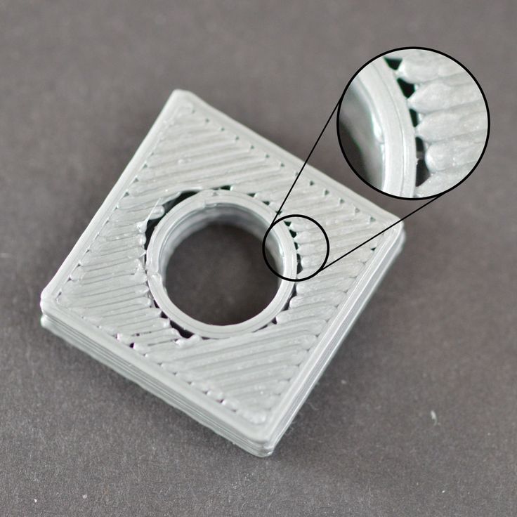
Other first layer problems
Description of the problem
The first layer does not adhere well to the table and some parts come off. Unwanted lines appear at the base of the model.
What causes this problem during 3D printing?
Such problems are a sign that the table has not been correctly calibrated (table calibration on the example of the Anet A8 3D printer). If the extruder is too far from the table, unwanted lines appear on the base and/or the first layer does not stick. If the extruder is too close, voids may appear.
Important: The print bed should be as clean as possible. Even fingerprints can cause the model to come off.
Solve the problem: The remaining problems of the first layer
- Calibrate the table. Each printer has its own table calibration features. For example, the latest Lulzbot models have an automatic calibration system. Ultimaker 3D printers are configured manually according to the corresponding guide.
 With Prusa i3 printers, you have to tinker a little longer and think for yourself.
 - Adjust the distance between the extruder and the table. If the extruder is too high, the plastic will not grip the platform. If too low, you may damage the table.
- Clean the print table. It is advisable to clean the table before each new print. Especially if you are using glue. Fingerprints and adhesive residue may cause the model to come off.
- Add glue. A small layer of adhesive can greatly improve adhesion. But do not forget that if you do not clean the table, then the use of glue can lead to the opposite effect.
- Special tape for non-heated table. If you are using an unheated platform, try applying tape to improve the contact between the base of the model and the table.
Cheklist of 3D Problem: the remaining problems of the first layer
- SLIDE Table
- Check the height of the extruder relative to the table
- Clean the table
- Use the print without heated
-
Non -rejuvenation.
 Description of issue
 Some layers in the model are misaligned.
What causes this problem during 3D printing?
Your 3D printer belts are not tight enough. The top of the print table is not stable. One of the Z guides is not a straight line.
Problem Solving: Layer Mismatch
- Check belts. Start by checking belt tension. You should feel resistance as you bring them together with your fingers. If the top of the belt is stiffer than the bottom, this is a clear sign that they need to be tightened.
- Check table top plate. Check the top plate and screw sets in the printer. Make sure everything is taut and aligned where needed.
- Check the Z-axis screws. Most 3D printers use a screw-nut pair instead of a ball screw. In general, this does not particularly affect the print quality, but over time, the screw may deform. Do not disassemble the printer to check the screws. It is enough to use a program like ‘Printrun’ and move the extruder up and down.
 If one of the screws is deformed, you will notice it. Unfortunately, it's almost impossible to fix this. But, on the other hand, this is a great chance to modify your 3D printer and replace the screws with screw-nut pairs.
 The printer did not feed the required amount of plastic. This may be due to problems with the plastic (for example, it has a different diameter), the extruder, or the plastic feed mechanism.
Friction has caused the table to stop temporarily. The reason may be that the vertical screws are not calibrated.
There is a problem with one of the screws or the Z-axis nut. For example, the screw is damaged, dirty, or not well lubricated.
Troubleshooting: Missing layers
- Mechanics check. A 3D printer, like any other piece of equipment, needs maintenance. If you have this problem, this is a clear sign that you should pay attention to its service. Start by checking the screws. Make sure they are well seated in the bearings/holes, with no undue misalignment.
- Screw alignment check. Check that all screws are aligned and not bent. You can appreciate this by turning off the power and carefully moving the extruder along the coordinate axes (depending on the layout of your 3D printer). If you feel resistance, then something is wrong.
- Damaged bearings. Damage to the bearings is manifested in the characteristic vibration during the operation of the 3D printer. If you notice vibrations, turn off the power and manually move the carriage with the extruder to find exactly where the bearing failed.
- Check lubrication. Many people forget about the lubrication of joints. But this is a very important point for the correct operation of your 3D printer. Regular machine oil is inexpensive and is great for maintaining printer connections. Before lubricating, check the guides. They must not be dirty. You need to apply a little oil. If you have applied too much lubricant, simply wipe off the excess with a rag.
 Naturally, after lubrication, check that the carriages run smoothly.
 - Plastic feed problem. The last possible problem is insufficient plastic supply. The solution to this problem may not be simple, so it is considered separately below.
3D Printing Problem Checklist: Missing Layers
- Check mechanics and make sure all screws are tight
- Check screw alignment
- Check bearings
- 9 Lubricate
- 9024 high models0240 Description of the problem
Dimples form on the sides of the model, especially on tall models. One of the most unexpected problems, the solution to which is usually not where you are looking for it.
What causes this problem during 3D printing?
In higher layers, the material cools faster because the heating from the table does not reach this height. Because of this, adhesion on higher layers is lower.
Problem Solving: Dimples on tall models
- Extruder temperature.
 Start by raising the extruder temperature in 10ºC increments. The specifications for your plastic should list operating temperatures. Try to keep the temperature within the specified range.
 - Cooler direction and speed. Check the coolers, make sure they work and point to the model. If so, try reducing their speed.
3D Printing Problem Checklist: Dimples on Tall Models
- Check extruder temperature and raise it in 10 degree increments
- Check the location and speed of the coolers aimed at the 3D model
Dimples, holes on the top of the model
Description of the problem
Dimples or even holes form on the top of the model.
What causes this problem during 3D printing?
The two most common causes are improper cooling of the top layer or insufficient thickness of the top layer.
Solving the problem:
hollows, holes on the top of model- Printable plastic diameter.
 Most common when printing with 1.75 plastic. Similar problems can appear in any 3D printer, but most often they appear when using plastic with a diameter of 1.75 mm, not 2.85.
 - Check cooler location. Any cooling problems are naturally related to coolers. At the start of a print, the coolers run slowly or turn off altogether, but after the first coat they should work much harder. Be sure to rate the performance of the coolers at the end of the print. If everything works, just in case, check the direction of their rotation. Cold air should flow to the model, and not vice versa.
- Set the fan speed in G-code. As the last layers of the model are formed, the cooling must be very intense so that the plastic does not fall into the holes of your mesh in the model. Cooler speed can be configured in G-code. The standard code for an on cooler is M106 and M107 for off. That is, adjust the maximum speed for the upper layers. An example would be a 1 cm by 1 cm cube with a layer thickness of 0.
 1 mm. In this case, the G-code obtained from CURA for the Prusa i3 3D printer will be 97 layers. Knowing that we have the 'Bottom / Top Thickness' settings set to 0.6mm, we can look at ;LAYER:91 and add M106 S255 at the end of the line. The M106 kicks off the cooler, while the S255 makes it run at full capacity.
 - Increase the thickness of the top layer. The simplest solution is to increase the thickness of the top layer. In most applications, this can be done in the advanced settings under ‘Bottom / Top Thickness’. It is desirable to form a minimum of 6 layers and 8 for extruders with a smaller nozzle diameter and, accordingly, a smaller plastic diameter. So if the layer height is 0.1mm, set ‘Bottom / Top Thickness’ to 0.6mm. If this does not help, increase the thickness to 0.8 mm.
3D printing problem checklist:
hollows, holes on the top of the model- Increase the diameter of the printing plastic
- Make sure the coolers are correctly installed and working
- Specify the speed of the cooler in manual mode - in G-code 9029 Increase the thickness of the top layer
Plastic residue
Problem description
Unwanted plastic residue forms between parts of the model.

What causes this problem during 3D printing?
When the extruder is moving and not printing (in idle mode), plastic residue is still coming in.
Troubleshooting:
plastic residue (more detailed article on troubleshooting plastic residue between parts of a 3D model)- Activate the Retraction option. Retraction is a very useful option, especially when it comes to finishing. It works very simply - before the print head begins to move, the plastic flows back into the extruder, and is not fed. Thus, the problem can be nipped in the bud.
- One-click backfeed activation. Most apps like Cura offer a one-click option to activate this option. The default settings are used, which is sufficient for most cases. However, if you want more flexibility, there should be other options. For example, you can set the minimum printhead path before activating plastic backfeed.
- Minimum travel (mm).
 Reducing the minimum path is usually the quickest fix if the default retraction settings didn't help. Decrease this value by 0.5 mm until the problem goes away. By the way, activating reverse feed will increase the speed of 3D printing.
 - Just cut off the rest of the plastic. This is not the most elegant solution, but by far the easiest and fastest.
Cheklist of 3D Problem:
Residues of plastic- Turn on the return submission of plastic (Retraction option)
- Set up the minimum path before starting the feedback
- Simplement
The 3D printer cannot feed the required amount of plastic (or at the required speed). As a result, thin layers are formed, layers with unwanted depressions or layers are completely absent.
What causes this problem during 3D printing?
There may be several reasons. The first is that the diameter of the plastic for printing does not match the diameter specified in the software for forming layers.
 The second - the amount of plastic supplied is insufficient, due to incorrect settings in the software. Well, perhaps your extruder is very dirty.
 Solve the problem: Insufficient supply of plastic
- Check the diameter of the plastic. Start with the simplest case - check the plastic diameter settings in your software. If you are not sure about the correct diameter, it and the temperature are usually indicated on the packaging of the plastic.
- Measure the plastic diameter. If the problem still persists, measure the plastic diameter manually and enter more accurate settings in your G-code generation software.
- Check the print head. In most printers, the print head is retracted from the print table. Check extruder. There should be no obvious contamination on it.
- Set the extrusion ratio. If there is no difference between the actual plastic diameter and the settings in the software, check the extrusion coefficient (extrusion multiplier or flow rate or flow compensation).
 Perhaps these settings are too small. Each program handles these settings differently, but the principle is the same - increase the value in the settings by 5% and restart 3D printing.
In Simplify3D open Edit Process Settings and go to Extruder tab - extrusion ratio set to 1.0 corresponds to 100%; If you are using Cura, open the Material tab and increase the Flow setting (you may need to activate the Flow settings in the Preferences panel).
3D Printing Problem Checklist: Plastic Insufficient
- Check Print Plastic Diameter
- Manually Check Plastic Diameter
- Check Extruder Cleanliness
- Increase the extrusion ratio by 5%
Too much plastic feeding
Problem description
Your 3D printer is feeding too much plastic. Because of this, the material peels off at the edges of the model.
What causes this problem during 3D printing?
This is usually caused by the Extrusion multiplier or Flow in your G-code generation software being set too high (see section above).
Solve the problem: Too much plastic feed
- Extrusion ratio. Open your layering software and make sure the extrusion factor is set to the correct value.
- Feed settings. If the previous point did not help, reduce the flow value (Flow).
3D Printing Problem Checklist: Too Much Plastic Feed
- Check extrusion ratio settings
- Reduce plastic feed value
Layer misalignment
Problem description
Bottom and top layers move relative to each other during 3D printing. Usually the offset is not as large as in the figure, but the above case can also occur.
What causes this problem during 3D printing?
Layer misalignment can occur for a variety of reasons, including a blow to the printer during printing! This problem may manifest itself due to incorrect belt tension or misalignment of screws. Or due to the fact that the extruder hooked the model and it shifted a little right during printing.
Problem solved: Layer misalignment
- Check printer stability. The 3D printer must be placed on a stable surface. Even slight shocks can cause the layers to shift.
- Check table stability. Most 3D printers have removable tables. Although this is convenient in terms of replacing it, over time the mounting screws can loosen. So it's worth checking them periodically.
- Check the bottom layers. If you are printing at high quality, the underlying layers may be torn off due to cooling. If a break occurs, the plastic rises and the extruder can hit it. In most cases, the model will come off the table, but if there is no lift, the powerful motors can push the model and the table. So if you have problems with the first layers, try reducing the rotation speed of the coolers.
- The print speed is too fast. Raising the temperature and increasing the feed can speed up 3D printing.
 However, even though the plastic will feed properly, your printer may not be able to handle the selected mode. If you hear clicks while printing, this is a sure sign that the printer is running at too fast speeds. In this case, check if the plastic breaks in the extruder itself, and then go to the settings for the actual speed of the 3D printer. The speed can be adjusted in your software to generate the g-code. If you are using Simply 3D go to ‘Other > Default Printing Speed (mm/min)’, if Cura go to ‘Basic > Print Speed (mm/s)’.
 - Check belts. If the layers are still shifting, it's time to check the belts. The tension of all belts must be the same. Timing belts tend to stretch over time (this is clearly manifested when the belts begin to slip on the pulleys). If the tension is very weak, you should consider replacing them. Strong belt tension can also be a problem. But usually this is a problem with DIY 3D printers. Some 3D printers (such as the Prusa i3) have special screws to adjust the tension.
- Guide shafts must be clean and lubricated. Over time, the guides become covered with dirt in places with maximum friction. This, in turn, can cause problems when moving and shifting layers. A quick cleaning and lubrication usually solves the problem.
- Curved or misaligned rails. If you notice that the print head position error occurs in a certain place, this may be a sign that one of the guides is deformed. You can check this by turning off the 3D printer and moving the print head along the coordinate axes. Check axle alignment. If everything is in order, remove the guides and lay them on a flat surface. If there is a bend, you will immediately see it.
3D Printing Problem Checklist: Layer Misalignment
- Check the stability of the 3D printer base.
- Check table stability.
- The first layers of the model should not form cliffs.
- The print speed is too fast.
- Check belts.
- Guide shafts must be clean and lubricated.
- Curved or misaligned rails.
Blocked plastic feed mechanism
Problem description
You start 3D printing, but no plastic comes out of the extruder. You took the rod out of the extruder, put it back in, but it didn't work.
What causes this problem during 3D printing?
After replacing the plastic, a small piece of bar remained in the feed mechanism. Most often, the break occurs at the very end. When you insert a new rod, the remnants of the old one block the flow of plastic.
The second option - the remnants of the old plastic dried up at the end of the extruder. In this case, the remnants of the frozen plastic must be removed manually.
Solve the problem: blocked plastic feed mechanism
- Unlock with a needle. If you're lucky, unlocking the feed mechanism is quick and easy. Start by removing the plastic. After that, on the control panel, select the option “heat up nozzle” (heat up the extruder) and increase the temperature to the level of plastic melting.
 If you have an Ultimaker 2 3D printer, go to Maintenance > Heat Up nozzle. For PLA plastic, set the temperature to 220 C. When the extruder is hot, use a needle or something with a small diameter and clean the hole (be careful not to burn your hands!). By the way, it is useful to clean the outside of the extruder.
 - Push through the old plastic. If the extruder is still blocked, you may be able to push the stuck plastic through with a new rod. Remove the plastic supply tube from the print head. Preheat the extruder to 220 C for PLA plastic and then, using a new rod, try to push the stuck plastic through the extruder. It may take some effort, but be careful not to bend the printer's horizontal guides. After that, you can clean the nozzle with a needle in accordance with the instructions from point 1.
- Remove and reassemble the extruder. In extreme cases, you will have to disassemble and reassemble the plastic feed mechanism. If you've never done this before, consider taking a photo or recording of your every step as you take the feed mechanism apart, as you'll need to put it back together afterwards.
 First remove the plastic bar. After that, read the instructions for dismantling the print head in the instructions for your 3D printer. Wear gloves while doing this, as the nozzle will be hot. Let's take a closer look at the Ultimaker 2 3D printer as an example. Move the print head to the center of the printer. Loosen the four screws on the print head. Preheat the nozzle to 220 C (for PLA). When the extruder reaches the desired temperature, turn off the power. Holding the cooler's plastic case, remove the rest of the interfering plastic. Clean the nozzle with a needle. You can also clean its outer surface. When the nozzle is cool, assemble the extruder, turn on the 3D printer and load new plastic.
3D printing problem checklist: blocked plastic feed mechanism
- Warm up the nozzle and clean it with a needle inside and out.
- Remove the plastic feed tube and try pushing through the remaining plastic with a new rod.
- Disassemble the feed mechanism and try to remove any remaining plastic.
Faulty plastic
Problem description
The plastic looks normal, is properly seated in the feed mechanism, and exits the nozzle when printing. This happens most often in Bowden-feed 3D printers rather than straight-feed 3D printers, as the plastic isn't visible or noticeable when it's broken.
What causes this problem during 3D printing?
Printing plastic breakage can occur for a variety of reasons, but mostly because the plastic is old or cheap. Most plastics like PLA and ABS last a long time, but if stored in poor conditions (such as direct sunlight), they can become brittle. If you use such plastic, no settings will help.
The second possible reason is the bar diameter, which may vary slightly depending on the manufacturer. And if the pressure in the feed mechanism is too high, it can break.
Troubleshooting: broken plastic
- Remove the plastic. The first thing to do is to remove the plastic from the 3D printer.
 If you are using Ultimaker, you can use the Maintenance and Change Material option. Heat up the extruder and remove the plastic.
 - Try another plastic. If the problem persists after reinstalling the plastic, try a different one to make sure the media quality is not the issue.
- Reduce feeder pressure. If the new plastic also breaks, loosen the pressure on the feed mechanism. Start 3D printing and increase the pressure until the slip is complete.
- Check nozzle. Check nozzle for cleanliness.
- Check flow and temperature. If problem persists, check nozzle heating. Also make sure the pitch is 100% and no more.
3D Printing Problem Checklist: Plastic Breakage
- Check the shelf life of plastic
- Check the diameter of the plastic
- Pressure in the supply mechanism
- Check the cleanliness of the nozzle and its temperature
- set the supply of 100%
Gloring of the rod
The description of the problem
of the span can be missed to slurry 3D printing stage.
 And it does not depend on the type of plastic. As a result, no plastic is fed.
 What causes this problem during 3D printing?
Clogged nozzle, insufficient feed force, incorrect nozzle temperature. As the motor rotor rotates, the small wheel that normally grips and feeds the plastic will pinch the bar and prevent it from being printed.
Solve the problem: bar slippage
- Help the feed system. If the plastic has just begun to slip, this will show up as a characteristic noise. Try applying some pressure to the bar to get this section through. This often helps and the 3D printer continues to print well.
- Adjust the feed force. Start by relieving pressure. After that, start increasing the force until the bar stops slipping. Heads vary in diameter, so some require fine tuning.
- Remove the plastic. More one solution is to remove and reload the plastic into the feed mechanism.
 After removing the bar, cut off the plastic over the place where the slip marks are visible and reload it into the feeder. If slippage remains, try this operation again. If that doesn't help, replace the plastic as this one is most likely no longer printable.
 - Check nozzle temperature. If you installed new plastic and the problem persists, or vice versa, check the nozzle temperature.
Cheklist of 3D Problems: slippage of the rod
- Help the supply mechanism with an additional effort
- Set up the force in the supply mechanism
- remove the plastic and load the
- temperature 9009
- Check the fill factor. This is checked in your software. A value of about 20% is quite acceptable. If less, problems may arise. This parameter should be increased for large models.
- Speed for printing inner layers. The speed at which printing occurs can have a direct effect on the quality of the inner mesh. If you see problems, try reducing the print speed of the inner grid.
- Change the mesh configuration. Most programs allow you to change the grid configuration. Squares, triangles, hexagons, etc. Experiment with these settings.
- Check nozzle. It may be that the cause is a clogged nozzle. At the same time, the outer parts of the model will print well, since plastic is fed more intensively on them.
- Check and Adjust Inflation Ratio of Model
- Reduce Inner Mesh Print Speed
- Change Mesh Configuration
- Check for Clogged Inner Nozzle
0237
Description of the problem
The printed model generally looks normal, but the inner mesh is visible through the outer walls of the model.
What causes this problem during 3D printing?
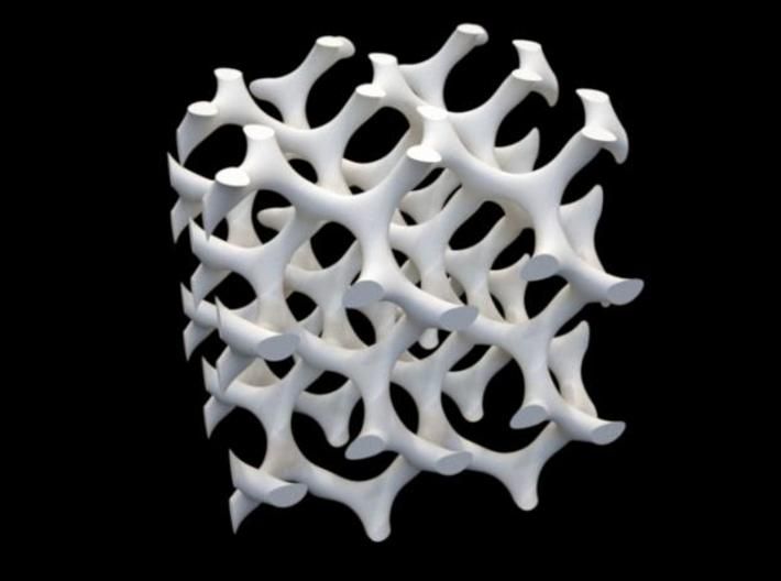
See-through problem occurs when your model has thin walls and the internal structure intersects with the outer wall line.
Normally the outer wall thickness should be proportional to the nozzle diameter. That is, if your nozzle diameter is 0.4 mm, the wall thickness of the model should be 0.5, 0.8, 0.12 mm, etc. If the proportion is not maintained, the effects of the clearance of the internal structure may occur.
Solving the problem: the inner mesh is showing through
- Check the thickness of the outer wall of your 3D model. Verify that the wall thickness value is proportional to the nozzle diameter.
- Thicken the outer wall. The simplest solution is to increase the wall thickness. Doubling the thickness will most likely help solve the clearance problem.
- Use the filling option after the walls have been formed. Most g-code programs have the ability to generate the internal structure after printing the outer walls.

- In Cura open 'Expert Settings' and in the Infill section activate the option 'Infill prints after perimeters'
- In Simply3D click on 'Edit Process Settings' then select 'Layer' and in 'Layer Settings' select 'Outside-in' next to 'Outline Direction'.
- Check the print table. Examine the printed model. If the effect is more on one of the sides, the cause may be in the calibration. If so, calibrate.
- Use this effect to your advantage. Depending on your needs, you can take advantage of the print sequence. If you need a model of high quality, with a good outer surface and at the same time the rigidity of the model is not critical, choose Outside-in printing (first the outer layer, then the inner filling). If the rigidity of the model is important, print on the Inside-Out principle, doubling the wall thickness.
3D printing problem checklist: Inner mesh shows through
- Check the outer wall thickness of the model.
- Increase the thickness of the outer wall.
- Use the filling option after wall formation.
- Check print bed and calibrate if necessary.
- Use this effect to your advantage.
Gaps between inner mesh and outer walls 3D Model
Problem Description
If you look at the bottom or top surfaces of the model, you will see gaps between the inner mesh and outer walls.
What causes this problem during 3D printing?
Gaps between outer wall and inner mesh used to be a common problem, but with the increasing accuracy of 3D printers, this is now a rare bug. However, there are new materials for 3D printing that can cause this problem again.
The most common cause of these gaps is that your software does not have an overlap of the mesh and outer walls set, or this value is set to "0". Your 3D printer considers this so that the wall and mesh should not intersect, and gaps may occur.
Another possible reason is the sequence in which you set the printing of the inner mesh and the outer wall.
 If you print the outer wall first, there may be no or minimal overlap. Accordingly, there is a chance of occurrence of these gaps.
 Solving the problem:
gaps between the inner mesh and the outer walls of the 3D model- Check the parameter of the intersection of the walls and the inner mesh of the model. This is the most common problem and is very easy to fix. Find the "Infill Overlap" option in your gcode generation software and increase this value.
- Cura defaults to 15%. Increase it to 30%.
- In Simplify3D these settings are in the 'Edit Process Settings > Infill > Outline Overlap' tab. Again, increase this value. This setting is directly related to the thickness of your head. So the % value will be % of the bar thickness to be printed. When tuning, do not set this value above 50%, as you will go beyond the walls.
- Form the inner mesh before printing the walls. If at the same time the inner mesh begins to show through, increase the thickness of the outer wall of the model as indicated in the section above.
- Increase extruder temperature. Some newer 3D printing materials (such as XT-CF20) may require finer temperature settings. Try increasing the extruder temperature by 5-10º. It might work.
- Reduce speed. You probably want to print your model faster, but faster speeds can cause a lot of problems. Especially if the 3D printer is not perfectly calibrated. If print speed is still important to you, try lowering it for the top layer only.
3D Printing Issue Checklist: Gaps between Inner Mesh and Outer Walls of 3D Model
- Check the intersection parameter between walls and inner mesh of the model.
- Print the inner mesh first and then move on to the outer walls.
- Increase extruder temperature.
- Reduce the print speed.
Object intersection
Problem Description
Parts of the model are missing or the final model is not rigid enough. The finished product and the 3D model are different and there are incomprehensible errors in the geometry of the printed product.

What causes this problem during 3D printing?
Virtual walls are one of the most common causes. Vertical walls only exist in 3D space, not in the real world.
For example, if you have two cubes in the real world and you try to match them, it won't work because the outer walls will not allow the two objects to intersect. In the 3D world you can combine two objects and still exist as two separate objects and your slicing program will also allow them to intersect in the virtual world.
For correct printing, these two objects must be combined into one, so that the inner walls disappear and one object remains.
Another possible problem - for example, you have a cube object and you have deleted one of its surfaces. In fact, you have an object with a hole. It may look like a 3D correct object, but it only exists as such in 3D space. Such an object cannot exist in the real world.
Deleting one of the surfaces leaves only two coordinates. The wall thickness, the third coordinate, has no dimension in the real world.
 We only see it in 3D modeling software. And when we start to form the layers of the model, the program will try to fix this bug and add the third coordinate. However, in more complex models, this can lead to unpredictable effects.
 Solving the problem: object intersection
- Use the latest slicing software. Most recent versions of slicing programs support automatic correction of intersecting objects, but it's still better to make sure that your 3D model is formed correctly.
- Set the Fix Horrible settings in Cura. In Cura, open the Expert Settings tab and have the Match All (Type-A) option selected in the ‘Fix Horrible’ settings.
- Set the Non-manifold settings in Silmplify3D. In the 'Process settings' select the 'Advanced' menu and then 'Heal' next to Non-manifold.
- Use layered representation. Use the layer view in your slicing software to check for problem areas in your model.
 A superficial view of the layers can help you quickly identify problem areas and fix the problem.
 - Use your software to fix object intersections. One of the easiest solutions is to use additional software to solve the problem. Blender and Meshmixer have built-in mechanisms for identifying problems and fixing the 3D model before slicing.
- Merge objects. It's better to fix your 3D model before importing it into the slicing software. When doing this, make sure that if your two objects intersect or overlap, you use the appropriate intersect, merge, or subtract function.
3D Printing Problem Checklist: Object Intersection
- Please use the latest version of your slicing software.
- Use the "Fix Horrible" option (in Cura).
- Use the “Fix Non-manifold” option (in Simplify3D).
- Use layered view to identify the problem.
- To fix errors, use additional software like Blender or Meshmixer.
- Merge objects.
No base for next layers
Description of the problem
You have loaded your 3D model into the slicing software and everything looks good. We started printing and as a result part of the model was printed well, and some parts - badly. This is a fairly common problem in 3D printing.
What causes this problem during 3D printing?
During 3D printing, each layer is built on top of the previous one. Naturally, if your model has a part that does not have plastic underneath (for example, as shown in the figure above - horizontally outstretched arms), printing problems will arise.
Ideally, the slicing software should somehow detect and point out this problem. However, in most cases, the programs will let us print without indicating that additional supports are needed for the model.
Problem solved: no base for next layers
- Add supports. The quickest and easiest solution is to add calipers.
 In most programs, this is done quite simply. For example, in Simplify3D go to Edit Process Settings > Support > Generate support material; you can customize the quantity, shape and specify other caliper settings. If you are using Cura, just select Support type in the Basic settings.
 - Make your own calipers. Software generated calipers may not suit you, so you can create your own in the base 3D model. This will require a little more skill, but can give fantastic results.
- Add an extra object to your 3D model. Most often, problems occur when printing hands and similar details. In this case, adding supports from the base of the model to the arm can also result in a problem, since the distance can be quite large. Considering that the calipers should be easy to remove, the high height may prevent them from being printed correctly. You can get around this by adding an additional object to your model (a piece of wall, a bench, a box, a flower, etc.
 ) and printing an additional rack already from this object.
 - Change the angle. For example, models of people whose arms are raised up to 45º will print well and it is absolutely impossible to print arms stretched horizontally at 90º relative to the body.
- Divide the model into separate parts. Another option is to divide the model into separate parts and print two pieces instead of one. The only problem that will need to be solved is how to combine the resulting parts into one model after printing.
3D printing problem checklist: no base for next layers
- Add sapphports in soft slicing
- Add calipers in the original model
- Add an object that can serve as a replacement of the caliper
- Change the angle of the problem node
- Separate the
Settlements
9024 problemsAs the model builds, the layers begin to shift. As a result, instead of a straight vertical model, displacements appear.
 In this case, the offsets are not the same over the entire height of the model. The offset can increase/decrease at different heights.
 What causes this problem during 3D printing?
The reason is quite simple. One of the belts connected to the stepper motor has lost tension. To eliminate model drift, it is enough to check the tension of the belts and the pulleys that keep the belts in tension.
At first glance, the solution to the problem is simple. However, before you fix it, you should find out which belt is causing it, as getting to the belt can be a difficult task.
Solve the problem: layer shift
- Check the X and Y axes. If the model moves to the left or right, the problem is in the X axis. Forward or backward, the problem is in the Y axis. Once you have decided on the coordinate, check the belts and pulleys. If you have a Prusa i3 3D printer, this shouldn't be a problem since the pulleys are mounted on the stepper motors themselves.
Learn more
Palle0240 Description of the problem
The printed product is missing an internal mesh or it is obviously incorrect
What causes this problem during 3D printing?
There can be several reasons why the internal structure of the 3D model does not print well. The most common is incorrect settings in your software for generating a G-code.
 It may turn out that the problem is a clogged nozzle.
 Solving the problem: Poor 3D printing of the inner mesh
3D Printing Problem Checklist: Poor 3D Printing of Inner Mesh
- Extruder temperature.
- Mechanics check. A 3D printer, like any other piece of equipment, needs maintenance. If you have this problem, this is a clear sign that you should pay attention to its service. Start by checking the screws. Make sure they are well seated in the bearings/holes, with no undue misalignment.