3D print around an object
A Guide to Embedding Components in 3D Printed Parts
Markforged Mechanical Features [MMF] is a series of blog posts detailing best practices for designing common traditional engineering parts and mechanical features for composite reinforced 3D printing with Markforged printers.
Last week, we explored overprinting nuts as a method for strong connections within your industrial strength 3D printed parts. In this post, we’ll take it a step further: by using overprinting to design multi-material parts when different materials are needed in different components of a part. As a brief overview, the process for overprinting is fairly simple. You start a print, pause it midway, embed components into the 3D print job, and then resume the print, allowing it to 3D print over the components you have embedded.
Just take the build plate off, drop in the nuts, and continue the print.
This could be used to develop a more integrated product, with electronic components embedded in 3D printed parts, it could be used when two materials are needed in the same component for desired material properties, or, in the case I will be explaining below, can be used to prototype parts to be made with more expensive manufacturing processes before committing to large batch quantities. For this post, I’ve designed a pair of 3D printed pliers with customizable jaws and an ergonomic grip.
For this pair of pliers, I wanted a stiff body, but comfortable grips. The Onyx is a bit rough for grips but pretty stiff (especially with fiber reinforcement), so I used Onyx and fiberglass to 3D print the body of the pliers and jaws of the pliers and a comfortable, tough nylon 3D printed grip.
The CAD model of a pair of 3D printed pliers with custom jaws and an overprinted grip.
Designing for overprinting fundamentally branches from design for assembly: how can you make putting components together easy and fast? Because you are embedding components mid-print, and the printer needs a flat surface to print on and the print head must not intersect with the part being embedded, designing for overprinting thus comes down to designing a good cavity. So here’s a guide on modeling and 3D printing parts with embedded components.
Designing the Void:
When designing for overprinting, as I mentioned before, you will be embedding parts in a void. When you start your part design, you should think about which face the part will print from right from the beginning, as you’ll need to know this in order to properly embed a part. For this part, I want to embed the main body of one side of the pliers into the grips. All these parts happen to be 3D printed, but only the grips have to be for this case. If you are overprinting a part, you may need it to entirely fit within the printed piece, or like in the case of this set of pliers, you may just want to place a section of the part in, in which case you will need ribs or some other sort of feature to keep the part constrained, as shown below.
These 3D printed pliers have ribs on their handles for secure overprinting mounts.
To create the void, you’ll need a good CAD model of both the part you will 3D print and the part you will embed, then creating the void is as simple as creating a boolean operation: subtract the part you will embed from the 3D printed part. If the part you are embedding has filleted or chamfered top edges, those features will need to be removed from the part you are 3D printing – a flat ceiling is necessary.
Subtracting the model of the part you want to embed from the part that will be printed to create the cavity.
In CAD, you will also need to check for is features in the embedded part that will intersect the build plate or the extruder head. If a section of the part you are embedding extrudes up above the cavity, there is a chance the build plate will hit it. To account for this, you either should try to ensure that the part you are embedding has a flat top surface, or that the extrusion is far away enough that there is no chance the extruder head will hit it, taking into account all the movements of the extruder head, including zeroing and dislocation checking. On the Mark Two composite 3D printer, the plastic nozzle is about 35 mm from the front of the print head, so anything features in your embedded part closer than that may get hit by the print head In these cases, you must orient your part such that the embedded part is jutting out toward the front of the printer. If it juts out of the side or back, the print head has a higher chance of knocking into it because of the way the print head zeros and runs dislocation checks. For example, in the pliers I designed, the jaws are raised higher than the flat the grips will be printed around. The jaws were spaced to clear the extruder head, at just over 35 mm.
If there are any components with extrusions above the surface the overprinting will take place, make sure they have at least 35 mm clearance from the printed part.
A really important step to remember when designing your 3D printed part is accounting for tolerance. After you’ve performed the boolean operation, you’ll need to offset each face by about .08 mm on every face to ensure that you will achieve a surface flush with the layer this part will be paused on. This also applies to the walls of the cavity – if you can’t fit your part inside the cavity because the cavity is just slightly too small, then you won’t be able to fix it unless you print a new one! Better be safe than sorry and design the cavity a bit oversize.
Oversizing your cavity is important to ensure your part fits well – in Autodesk Fusion 360, I offset all the internal cavity faces by 0.
 08 mm.
If your top surface is an odd geometry, you’ll need to design a secondary insert to add to the cavity to ensure a secure fit that forms to the top surface of the embedded part. This process is explained in the latter half of my embedded nuts blog post from last week, and the exact same process can be implemented for other components. If you would rather not do this, one way to get around this involves angling the ceiling of the cavity above the inserted part, but then that means the component, depending on it’s geometry, may be loose within the 3D printed part.
This cross section shows a square nut embedded at an angle, with a triangular piece to fill the gap.
Usually, when designing for overprinting, I try to avoid the use of support material. However, in some cases it it necessary to the design, and that’s not a problem: support material can be easily removed from the cavity before placing in the embedded component.
Adding pauses in Eiger:
In Eiger’s internal view menu, you can easily add a pause after a selected layer, making it easy to embed parts into your 3D printed components. Find the layer just before the roof of the cavity starts to print, and click “Pause After Layer” At that layer, you can note the time it will take to get to the pause and use that to determine when to check in on your print job.
Select “Pause After Layer” to add a pause after the printer finishes the selected layer.
Remember, if your parts do not require support material, it is a good idea to turn supports off. If they do, however, that’s fine! You’ll be able to remove them, as I’ll explain later.
An Eiger screenshot of the 3D printed grips I’ll be printing.
When you orient your part on the build plate, keep in mind the accessibility of the part. You’ll want to be able to quickly pop the part in and resume the print, so orienting your part so that you can easily get to it. For this part, I placed it all the way up by the front so I could easily snap in the body of the pliers.
Set up your part in Eiger so it is easily accessible once the print pauses.
Adding the Part:
When it comes time to add the part to the print, timing and speed are key.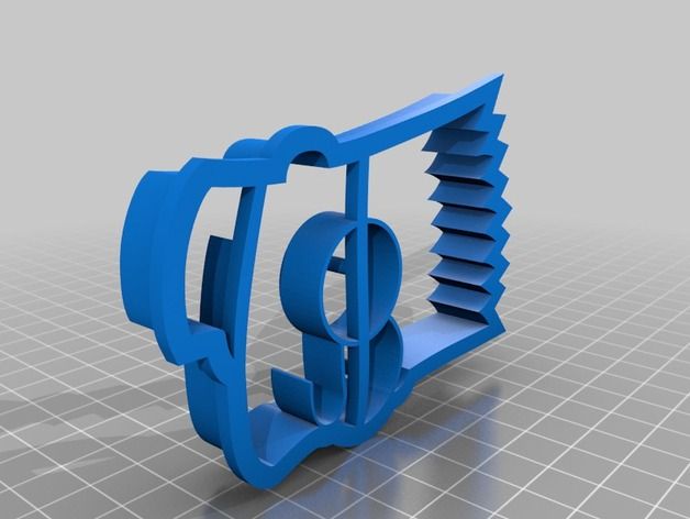 As Markforged printers are FFF (Fused Filament Fabrication) machines, the plastic is heated, extruded, and cooled. When it cools, it shrinks slightly, which, if the print is paused for long enough, can cause much weaker layer adhesion on that plane. When placing a part into a print job, you want to do it as quickly as possible to reduce this risk. Using Eiger, you can estimate about when your printer will pause, so you can show up on time and be prepared for when your printer pauses.As I explained earlier, support material may be necessary due to other features in your design. For example, this grip requires supports because it has a complex bottom surface. In my case the void that I designed will fill with supports, but it’s not a problem – if this happens you can just pull them out before inserting the part.
You can easily pull supports out of a cavity before inserting an embedded part.
Now it’s time to place the part into the print. This is why tolerances are so important.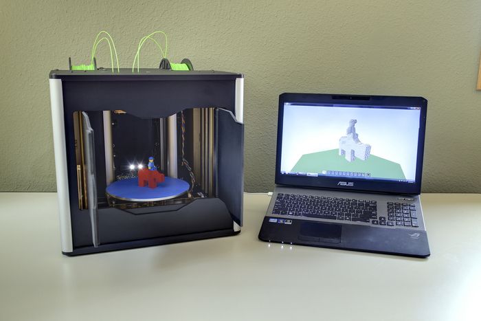 You need to make sure that the embedded component is perfectly flush or slightly below the layer that the print is paused at. If it is slightly raised, your print head will jam against the embedded component and mess up the entire print, or the filament will jam when trying to print over the component.
embedding the 3D printed handle in the ergonomic grip.
When a print pauses on the Markforged 3D printer, the print head moves out of the way, allowing you to easily remove the build plate from the printer and add your part. The kinematically coupled build plate ensures the print bed will snap right back in place when you want to continue.
The build plate snaps into place with 10 micron accuracy.The 3D printed grip continuing to print over the handles of the pliers.
If you are adding a component that is not a Markforged 3D printed part, then you will need to add a layer of glue to the top surface of the part. This glue is normally put on the build plate at the beginning of a print to help with build plate adhesion, and in this context we are using it for the exact same reasons – the nylon will stick better to the top surface of the part.
The completed print job for these 3D printed custom pliers.
And after printing two of these and snapping in a small pin at the joint, I now have a pair of 3D printed pliers with customizable, swappable jaws and ergonomic grips!
The finished set of 3D printed pliers.After printing, the pliers can be easily assembled, and you can make modular grips for the jaws!
If you want to make these yourself, here are the files:
Pliers and pin MFP (requires Onyx and fiberglass)
Grips MFP (requires Nylon)
Custom JAW MFP (requires Nylon)
Pliers STL
Pin STL
Grip STL
Custom Jaw STL
Other Applications:
The applications of overprinting range far and wide because it allows you to create fully integrated assemblies that could not have been created any other way. While this example represents embedding a section of a component to create an ergonomic grip, you can also embed whole components and the same rules apply. For example, you may want to prototype a part that will eventually be overmolded, or you may want to create a part with embedded electronics for an integrated electromechanical system. You may want to embed hidden nuts or bearings into a 3D printed part, or create a multimaterial build with a single plastic extruder 3D printer. If you have tried out overprinting and embedding components in 3D printed parts, please share with us on Twitter, Instagram, or Facebook!
Why Do 3D Printers Make an Outline/Skirt? – 3D Printerly
You might have noticed, when a 3D print is about to start it makes an outline wider than the actual object itself. It seems pretty odd at first, especially to beginners, so I set out to answer why 3D printers actually make an outline.
Why do 3D printers make an outline? 3D printers make an outline, called a skirt mainly to ensure that the nozzle is primed and ready to smoothly print your 3D object. Sometimes your nozzle can be slightly blocked, so making this outline can remove this blockage so your first layer comes out clean and forms a good foundation.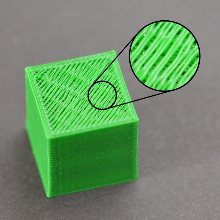
This is the basic answer which explains the question, but there are some more details you will want to know in terms of these outlines and how to make sure it’s done properly in your settings.
Why is a Skirt/Outline Important When 3D Printing?
In your 3D printing journey you may have heard of skirts, brims, and rafts; three terms which help your prints finish more successfully. In this case we are talking about a skirt, which is named quite well because it looks like the skirt of your main print.
I’m going to describe its importance and why they are used.
To Build a Great First Layer
It’s always good practice to print at least one single-layer skirt before your main print is started. A skirt is a great way to get your material flowing and evenly extruding before going in and building the actual layers.
Similar to when you test your pen on the corner of your page before you start writing.
The first layer of a print is arguably the most important.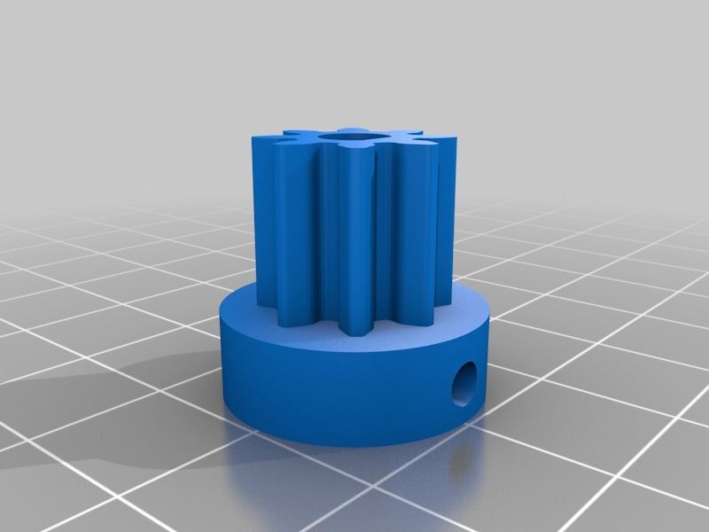 Once it’s completed, the success rate of your print completing without issues goes up substantially.
Since your printer works by extruding plastic filament through your heated nozzle, it can take some time to build up enough pressure to extrude as smoothly as it needs to build up a solid foundation with full layers.
A lot of times after laying the skirt down, you’ll see a little blob of plastic come out which is just the leftover material from your last print.
You wouldn’t want this coming out during your vital first layer, so it’s better extruded beforehand, around your main print.
A skirt is also a good way to see just how well your bed is levelled and whether the nozzle and material is creating enough contact with the bed’s surface to create a sturdy first layer.
When the nozzle is too high off the bed, it doesn’t create enough downward pressure to stick to the bed firmly. When it’s too close to the bed it doesn’t flow through evenly and can even scrape the bed surface.
Making sure you add a skirt to your 3D print will save you a lot of time, filament and frustration in the long-run so definitely add this to your 3D printing routine.
To Gauge How Well Your Printing Parts Are Working
This ties in with the first layer, so it gives you the insight into how well your printer, and its parts are working when printing.
After printing out one or two layers of the skirt, you’ll easily be able to tell whether you need to stop your print and do some troubleshooting, or if things are ready to continue to create a high quality model.
If things aren’t flowing so great you know you might need to adjust your printing temperature, increase your bed temperature, clean out the nozzle, re-level the bed and so on.
It’s a great way to save time from going halfway through a print and realizing that there are many imperfections on your print.
Sometimes after changing materials or colors you may still have some left in the nozzle. A skirt will print this out first so your changes are properly implemented before it’s printed to be a part of your final object.
Use the Skirt as a Barrier
Most people don’t think about this use, but you can use the skirt as a thermal or draft barrier which protects your prints. A print bed which has a nice skirt around it can provide slight insulation and protection from drafts which can easily alter temperatures around the room the printer is in.
It can help with surface warping with these protection layers.
If you don’t have an enclosure and sometimes experience these adverse environments, a skirt can be just enough protection to have your print finish without issues.
How Do I Add a Skirt to my Prints?
This will depend on your slicing software, but it’s pretty straightforward for all the main ones out there. You simply want to go into your slicer and look into your settings. It will usually be under ‘print settings’ then under some type of adhesion title.
To add a skirt on the Cura slicer:
- Go to print settings near the top right corner
- Scroll down to the ‘Build Plate Adhesion’ row and expand by pressing the down arrow
- Beside the ‘Build Plate Adhesion Type’ put in ‘Skirt’
- Beside the ‘Skirt Line Count’ put in the number of skirts you want your prints to have.
If the skirt line count is on 0, this means it will disable the skirt. You want to have at least one skirt in your prints.
A lot of times, when you download the STL files from a website like Thingiverse, they will have already added the skirt in the settings, so you won’t have to manually add the skirt, but not every file that you download will have it.
What Will Happen If I Don’t Add An Outline/Skirt to my Prints?
You might be thinking, what’s all this hassle about skirts and not want to go through worrying about adding a skirt.
The end result here is that you’ll save a few centimeters of filament in the very short term, but if your first layers don’t come out up to standard because you avoided using a skirt, you’ll just be giving that saved filament right back and even more than you saved in the first place.
I don’t see there being much advantage over removing a skirt from your printer settings, so I wouldn’t recommend it. The main reason you wouldn’t use a skirt is because you don’t know just how beneficial they are to your 3D printing process.
Since you’ve read this article I’m sure you now know the benefits and will continue using a skirt in your 3D printing journey!
short tips for the transition from a CAD model to a printed object / Sudo Null IT News
was withdrawn from publication due to a technical error. Please be understanding. Thank you!
Whether it's just a hobby or a source of income, 3D printing is always based on product design. Those accustomed to traditional technologies will have to rethink the entire approach to product design and manufacture.
When the project is ready, a number of additional operations are performed: setting the orientation of the model and other parameters that ensure the proper printing process. In addition, it is necessary to take into account the fact that most 3D printers allow you to choose the degree of filling the model with cellular structures. The correct choice of this parameter provides protection of the object from deformation and destruction during the printing process, as well as significant savings in material and reduction in production time.
Finally, the last factor influencing the success or failure of the 3D printing process is the strength of the connection between the model and the table. If the workpiece is separated from the table during printing, then all the work will go down the drain.
Here, we'll walk you through the 3D printing process and give you some simple tips on how to use additive manufacturing in the design phase. In addition, we will dwell on the methods of preparing a finished project for printing, and also consider ways to securely fasten the workpiece to the table.
These guidelines apply primarily to Fused Deposition Printers (FDM) printers, but may apply to other types of printers as well.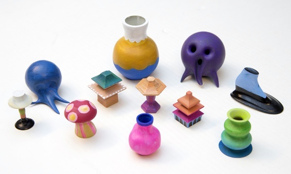 The process of obtaining a finished part by 3D printing is basically the same regardless of the method used.
Designing an object
Any 3D printing starts with construction. If you are developing a product yourself, then you need to build a 3D model of it in a computer-aided design (CAD) system to turn the designer's idea into reality. In this case, the object can be both very simple and very complex. However, too thin and too small models should be avoided.
3D-CAD from Siemens from this article for 49900r (90% discount), the promotion is valid until March 20, 2020. Read more>>
Saving the file in a special format for printing
To print an object, its model must be saved in a special file format - for example, STL, which has become the de facto standard in the world of 3D printing. In this format, model surfaces are represented as a grid of triangles. Simple surfaces are broken down into a small number of triangles.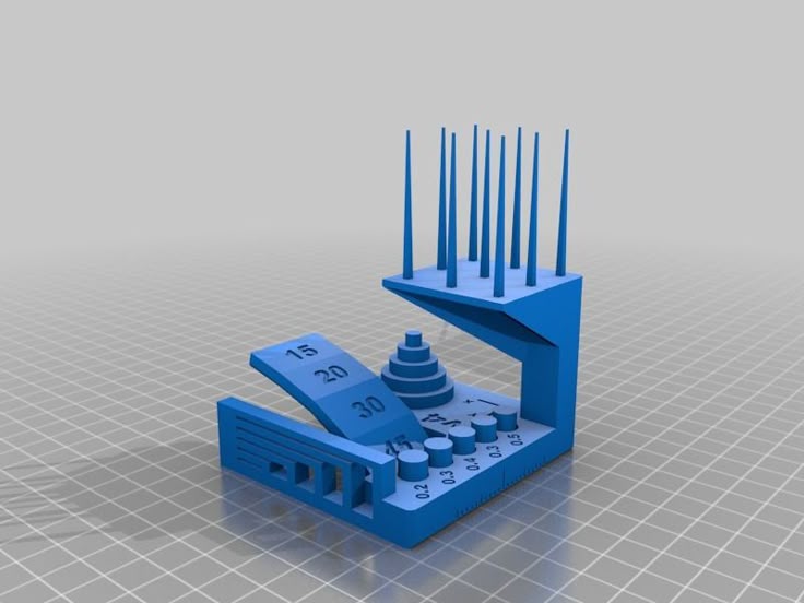 The more complex the surface, the more triangles you will need. Today, other formats are used in 3D printing, in particular, the 3MF format developed by Microsoft. But the most common is still STL.
CAD systems make it very easy to save the model in the desired format: just click the Save As command. To improve print quality, it is desirable to set a number of settings for saving to the STL format - for example, the tolerance during transformation and the angle of the plane. The lower the conversion factor and the better the angle, the smoother the printed part will be.
Opening the file in the slicer program
Most, if not all, 3D printers come with their own slicer software. The slicer loads the STL file created in the CAD system and cuts it into layers, and then creates a control program for the printer.
Place the model correctly in the print space
After entering the print settings, the model (or several models) needs to be placed on the printer table.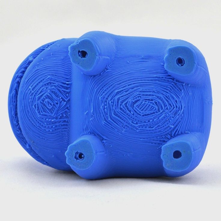 You can print many objects on one table at once. At the same time, compared to printing a single object, the time slightly increases, but in general it still turns out to be less. Here are some tips for choosing the right model orientation.
Set parameters
In the slicer program, the user sets parameters such as print speed, material consumption, nozzle and desktop temperatures. Most slicers have simple settings for beginners. In this case, most often there are also advanced settings so that experienced professionals can achieve optimal results. Advanced settings include percentage infill, amount of backing material, and type of backing or raft (this is a small, thin base that keeps the printed part stable. The backing is removed when it's finished). The number of options is truly endless. Specific settings vary depending on the brand of printer. It's easy enough to set them up.
Sending the control program to the printer
After setting the print settings, the placement of future objects on the table, their orientation and quality, it's time to finally start the printer. It is enough to press the Print button and find something to do while the production is in progress. Depending on the complexity of the design, the process takes from several minutes to several hours.
Finishing
Finishing includes removing the printed part from the table, as well as removing the support material by melting, mechanical separation or dissolution (depending on the design of the printer). The part may require some light sanding or polishing, but overall a properly printed object looks good from the start. Other types of finishing are placing plastic parts in a container with acetone to smooth out surface roughness, gluing (if the dimensions of the structure exceed the dimensions of the 3D printer or individual elements of the object must have different orientations), drilling holes and painting.
3D printing process
3D printer design considerations
Eliminate sharp corners
If the direction of the surfaces changes abruptly (for example, a vertical wall intersects with a horizontal overlap), then such a model is difficult to print.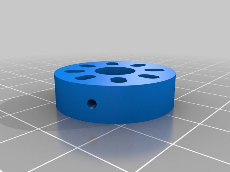 The printer will build excessive inner surfaces, wasting too much material. There are two easy ways to prevent this: add chamfers to smooth out where the surfaces meet, or round the corners so the printer gradually builds a vertical surface. In addition, rounding will increase strength, since destruction most often occurs at sharp corners.
Elimination of thin walls and small geometries
Layer by layer fusing technology consists in supplying hot plastic through a nozzle with the formation of a printed object layer by layer. The thickness of the extruded plastic layer cannot be made smaller than a certain limit, depending on the diameter of the nozzle and the speed of the print head. Excessively thin-walled details are difficult to print - often the result is a chaotic weave of fibers. If the part can be printed, it is very fragile and breaks easily.
Too thick walls - also bad
On the other hand, if the walls are too thick, they become brittle and crack easily. This is especially important when printing from materials other than resins, as excess thickness during the manufacturing process leads to internal stresses in the part. Even when printing from plastics, material is wasted on walls that are too thick and time is wasted.
Removing large overhangs
3D printers allow you to create amazing shapes and surfaces, but they are not capable of printing directly in the air. If there is a void in the part with material above it, additional support material must be used. Most slicers add material automatically, but require you to specify the orientation and volume of the support structure. Printers with a single nozzle create an array of thin columns, which then have to be broken off. The result is an uneven surface. Therefore, it is recommended to avoid large overhanging elements whenever possible in order to reduce the need for support material.
If such an element is unavoidable, you can try to flip the object. Most printers are capable of printing overhanging elements with an angle of about 45 degrees. At a certain height, the edge of such an element may sag somewhat. The actual capabilities of a particular printer are determined by trial and error.
Holes shrink
Remember that the part is made of heated plastic. As it cools, it inevitably shrinks. Therefore, holes and other critical structural elements have to be made larger so that after shrinkage their size is as close as possible to the required one.
However, if you need to make a tight tolerance hole, it is better to print it with a smaller diameter and then ream it with a suitable tool. This is especially true for holes whose axis is parallel to the printer table.
Increasing the footprint
If the area of contact between the object and the base is small, the part may separate from the table during printing. To prevent this from happening, wide bases are added to the model legs, which are installed on the printer table.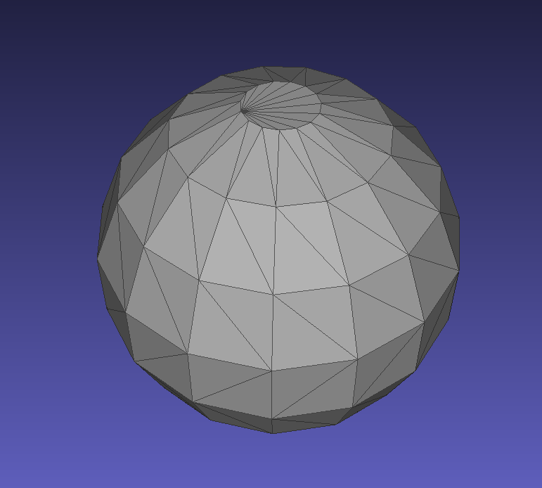 In general, the closer to the table, the more material must be added to the support. There are other ways to securely fasten the part to the table, which we will discuss a little later.
Special moves
The right approach to design makes printing easier. In addition, there are special post-processing techniques that are important to be aware of.
Place round surfaces vertically
The model should be oriented so that the minimum amount of support material is used. Ideally, it should rest on the table with a large flat edge. In addition, circular geometry must be placed so that the circular faces are vertical. If we look at the printer table from above, we should see a round silhouette of the object. In this case, the part comes out as symmetrical as possible with the formation of a solid round structure.
Place voids and holes vertically
If there are voids in the model (for example, it is a rectangular pipe), it is desirable to place such voids vertically in order to reduce the volume of the support material. If you print the pipe in a horizontal position, you will have to provide support for the entire inside. If you put the pipe on the end, then no support is required at all.
The same is true for holes: to get a hole with a straight axis, it is best to print it vertically - in the form of a stack of rings, which avoids warping or deforming a round hole into an oval one.
Set print quality settings
Proper selection of print parameters, such as STL conversion tolerance and slicer software settings, allows parts to be produced with a surface quality that matches that of cutting. However, this entails an increase in print time. When choosing quality parameters, one should proceed from the purpose of the object: is it a finished product or a prototype? Will the part be visible or hidden?
The quality parameters also affect the shape of the holes in the part. In CAD files, holes are represented as a set of straight lines at an angle to each other.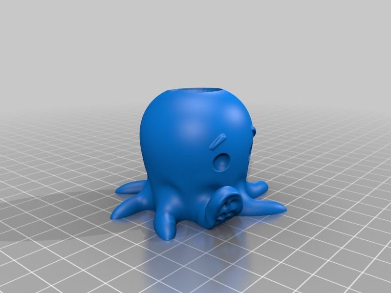 The higher the quality of the model in the saved STL file, the less the circle looks like a polygon.
Reducing the layer thickness
To obtain the best quality, especially when using layer-by-layer deposition technology, it is necessary to reduce the thickness of the layers. It does increase the print time, but the end result is worth it!
Optimizing the filling with honeycomb structures
In terms of strength, objects do not have to be solid. Similar to a honeycomb, printers can create a honeycomb infill that balances strength and saves expensive polymer material. However, if the printed part serves as a prototype for strength testing, and the serial product will be manufactured by traditional methods, and also if the part is subjected to certain types of mechanical stresses and pressures, a solid design will be preferable.
Choosing a material
The success of printing largely depends on the correct choice of material.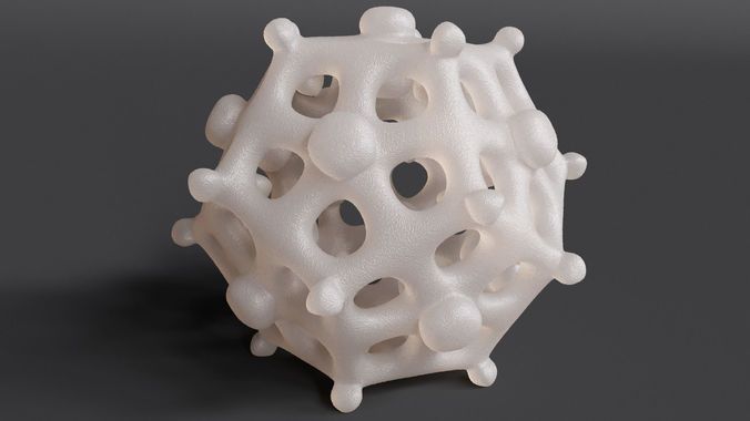 Materials have different properties. For example, the melting point of thermoplastic polyurethane (TPU) and polylactic acid (PLA) is lower than that of acrylonitrile butadiene styrene (ABS). In addition, the material is taken into account when choosing the type of support structures. For an object made of polylactic acid, supporting elements can be made from the same polylactic acid, since it will be quite easy to separate them from the finished part. If the part is printed from ABS plastic, then the support elements must be made from a different material, and it is better not to use such elements at all in thermoplastic polyurethane parts.
Cellular filling
A solid body is not always the best choice for 3D printing. Printing solid parts has its advantages, but the internal honeycomb structure saves both expensive material and time.
Creating objects with a specified degree of filling with honeycomb structures is a unique opportunity for 3D printing. Moreover, it is not required to design such a structure: this is done by the slicer program. As a rule, it is enough to set only the percentage of filling (the closer it is to 100, the more solid the object will turn out) and select the type of cells, if the printer has such an opportunity.
In addition to saving time and material, the internal honeycomb structure has many other advantages.
Cellular filling prevents warpage
Printing large objects as a single piece introduces a danger of warpage. By reducing the infill percentage, the air during printing passes through the part, providing more uniform cooling and eliminating warpage.
Cellular filling does not lead to loss of strength
Printing cells instead of solid material does not reduce the strength of the part. In many cases, a honeycomb part is strong enough for the chosen application, but lighter and less material intensive.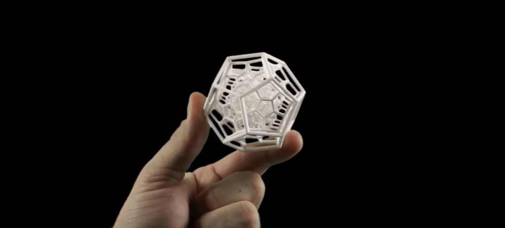
The function determines the choice of cell geometry
Most slicers support a wide variety of cell geometries. The optimal option is determined by the functional purpose of the object. Standard box padding simplifies printing, while hexagonal and triangular boxes add strength. Wave fill allows the object to bend or twist.
How to choose the right filling percentage?
In general, the strength of an object increases as the percentage of infill increases. Most printers have a default infill percentage of 20, which is optimal in some cases but too high or too low in others. Consider mechanical stresses in the printed object and increase the percentage of infill in areas where greater strength is required. If high strength is not required, choose the lowest possible filling. This saves material and speeds up printing. Most often, the selection of the optimal percentage of filling is done by trial and error.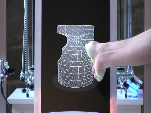
Ways of fastening the workpiece to the table
“Rafts”, “brims”, “skirts” – these terms sound funny, but they just refer to the three main ways of attaching a 3D printed part to a printer table. Let's take a look at each of these methods and their areas of application.
Skirt
The skirt involves creating a few rings around the object at the beginning of the print to make sure the plastic is extruded normally. The skirt is not in contact with the object at all. It surrounds the printable area and helps start the fusing process. When creating a skirt, a large volume of hot thermoplastic polymer passes through the nozzle. This prepares the printer for printing the part itself. This guarantees good adhesion to the table and obtaining smooth surfaces of the object.
Brim
The brim is a wide, flat area connected to the main object as a support base (think of a brim of a hat). It is very similar to a skirt, but connected to the model. In addition to all the advantages of a skirt, the brim keeps the edges of the object being made on the table.
When printing, the outside of an object often cools faster than the middle, causing the edges to curl. Brim prevents this phenomenon by holding the edges.
Raft
A raft is a detachable base, made in the form of a thin mesh platform, located under the entire object (which lies on the raft). To create a raft, the printer first prints a flat plate in two or three layers, and then begins to manufacture the object.
The rafts provide excellent adhesion to the table surface and also provide a strong print base. This is especially useful when making small and oddly shaped parts that do not fit well on the table, as well as thin-walled objects.
After printing is completed, in most cases the raft will separate easily from the part.
If the printer does not have a heated desktop function
Rafts are used if the printer does not have desktop heating.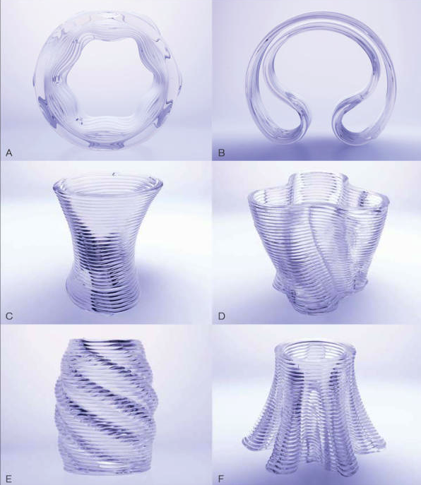 In this case, excessive adhesion becomes a problem.
An alternative method is to apply adhesive paper tape to the printer bed, with the edges down if possible (this also protects the bed). You can also use packing tape, but it is usually more expensive.
If buckling does occur or the object separates from the table, apply a dissolvable glue stick to the adhesive tape. This will enhance adhesion.
Find out the features of a specific 3D printer and take them into account when preparing a model
3D printing is not only a science, but also an art. Effective design for subsequent 3D printing requires an understanding of the technological process, taking into account its features and the purpose of the future object. This will greatly improve print performance.
Using Solid Edge in 3D printing
Not all CAD systems are suitable for 3D printing
The capabilities of the applied system should not limit the designers. Our Solid Edge system is designed with the latest 3D printing technologies in mind. Various 3D printers and 3D printing services are supported.
Take it to the next level with specific techniques for designing 3D printed parts
Generative modeling in Solid Edge opens up new possibilities: the designer selects a specific material, sets the design space, allowable loads, restrictions and target mass of the part, and the system automatically calculates the desired geometry. As a result, 3D printing methods can produce the most complex shapes.
In addition, when building models, the use of the results of three-dimensional scanning is provided. Solid Edge successfully combines the traditional boundary representation of solid models (B-Rep) and the representation of surfaces in the form of a grid of triangles, which avoids time-consuming transformations that are fraught with errors.
If you've already downloaded an STL file for printing, our unique synchronous technology makes it quick and easy to edit your imported models in Solid Edge in preparation for the process.
Printing with your own printer or submitting an order to a 3D printing service provider
Printing in Solid Edge on a local 3D printer is done using the 3D print command. Models can be saved in STL and 3MF formats, or sent directly to Microsoft 3D Builder. If you don't have your own 3D printer or need to try out different materials and surface finishes, Solid Edge allows you to directly submit your models to cloud-based 3D printing services (such as 3YOURMIND). You immediately receive quotes for the production of parts from various materials with its subsequent delivery directly to your door.
3D-CAD from Siemens from this article for 49900r (90% discount), the promotion is valid until March 20, 2020. Read more>>
Problems, defects, 3D printing errors and solutions
Often during the operation of a 3D printer, problems may arise due to which defects appear on the finished model. Or instead of a neat product, plastic noodles suddenly appear on the table.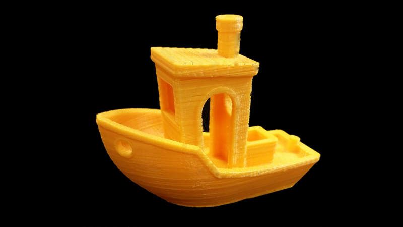
In fact, the causes of defects can be conditionally divided into 2 types - these are physical and software.
Physical ones are those that arise due to problems with the mechanics or any other causes that can be eliminated physically. These include problems with printer mechanisms (belt tension, backlash), clogged or deformed nozzle, incorrect table geometry, etc.
Software - these are defects that occur due to incorrect slicer settings or, less often, errors in the printer firmware. For example, incorrectly selected print speed, retract settings, incorrectly selected temperature for plastic, etc.
Very rarely, the problem may lie in the wrong or “flying” printer firmware (although usually the printer simply will not start then), overheating of some boards during printing, etc. These are rather special cases, so we will not consider them.
Model peels off or does not stick to platen
This is the most common 3D printing problem.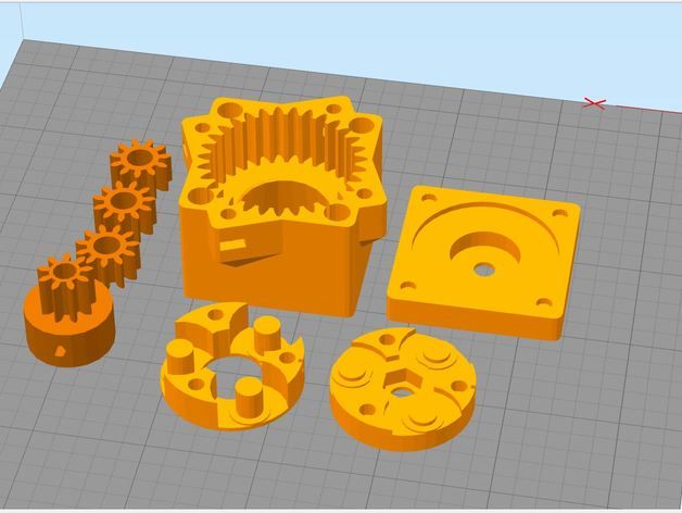 Every 3D printer has had a case when the first layer treacherously rolls, clinging to the extruder, or the most offensive - when it tears off a partially printed model from the table. The first layer must stick tightly otherwise nothing will be printed.
Gap between table and nozzle too large
This is the most common reason. You just need to set the correct gap between the table and the nozzle.
Modern printers often use an auto-calibration (auto-leveling) table system or an auxiliary table leveling program. To calibrate such printers, use the instructions. If there is no manual, it can be downloaded from the manufacturer's website.
If you have a simple printer without auto-calibration, a self-assembly or KIT kit, use a probe or a piece of paper folded in half to calibrate. The probe should be slightly pressed against the table by the nozzle. Before calibration, the table and extruder must be heated. Align the table surface over each adjustment screw (there may be 3 or 4) in turn, and only then check the center point.
If you're having trouble getting your table surface perfectly level, try raft printing. Raft is a thick substrate in several layers that is printed under the model. It will help smooth out the slight curvature of the table.
A small cheat sheet to determine the correct gap on the first layer
Plastic with poor adhesion
Some types of plastic, due to various reasons, such as large shrinkage, do not adhere well to the surface of the printing platform. In this case, try using stickers or special 3D adhesives to improve adhesion between the table and the first layer of plastic.
In the early days of 3D printing, there were experiments with different homemade 3D adhesive recipes. ABS diluted in acetone, BF glue, sugar syrup and even beer. Some experiments have been successful. Until now, some enthusiasts use some types of hairspray or glue sticks as 3D glue. But still they are inferior in their properties to industrial 3D adhesives.
Some types of high temperature plastics with a high percentage of shrinkage (ABS, Nylon, etc.) may peel off the table during printing. This is due to uneven cooling and “compression” of the model (the lower layers have already cooled down, but the upper ones have not yet). For such plastics, it is imperative to use a 3D printer with a heated table and a closed case.
Plastic temperature too low
The hotter the plastic is when it exits the nozzle, the better it will adhere to the print bed. It is better to print the first 5-10 layers at a higher temperature (+ 5-10 degrees) and turn off the blower fan.
Wrong first layer settings (speed and thickness)
A thicker layer sticks easier, so the standard first layer is 0.3mm thick. With an increase in print speed, the heating block may simply not have time to heat the plastic to the desired temperature and it will stick to the table worse. Before printing, check the speed and thickness settings of the first layer in the slicer.
A lot depends on how the 3D printer prints the first layer. Try to control the printing of the first layer and only then leave the printer to work alone.
Plastic does not choke out of the nozzle
The printer has already begun to print, but the print table remains empty. Or part of the model did not print.
Clogged nozzle
In 3D printing, a nozzle is a consumable. The nozzles are clogged or worn out (frequency depends on the type of plastic). The simplest thing is to replace the nozzle. But if there was no spare at hand, you can try to clean the old one. To do this, there is a whole set of thin needles. Or you can heat a clogged nozzle above the melting point of the plastic and “burn out” the blockage. But later it is still better to replace the nozzle.
Low temperature nozzle
You need to increase the temperature of the extruder in the slicer settings or check the thermistor and heating block. Sometimes the thermistor may not read the temperature correctly due to a malfunction or incorrect 3D printer firmware settings.
If the problem occurs after replacing the thermistor - contact the manufacturer or read articles about PID tuning.
Empty extruder
As the extruder heats up, plastic begins to ooze out of the nozzle. Because of this, the extruder may start printing half empty. Because of this, part of the first layer is not printed. You can push the plastic manually by simply pushing the bar into the nozzle. Or solve this problem programmatically - in the slicer, add a contour print around the model (one line).
Some manufacturers and 3D enthusiasts add a line print on the edge of the table at the beginning of each GCode. This is done so that there is plastic in the nozzle by the time the model is printed.
Feed mechanism does not push through plastic
The plastic pushes the feed mechanism to the extruder - a motor with a special pulley put on the shaft. If for some reason the plastic is not pushed through (nozzle clogged, extruder temperature low, etc.), then the pulley “gnaws” through the bar. You need to push the plastic bar with your hands or cut off the damaged piece.
Elephant foot
The first layers of the model are wider and protrude beyond the boundaries of the model. This is due to the fact that the upper layers put pressure on the first ones that have not yet cooled down and flatten them.
High table temperature
Due to the too high temperature of the table, the lower layers remain soft for a long time. Try lowering the table temperature. It is better to reduce gradually (in increments of 5 degrees). You can try to turn on the blower when printing the first layers.
Small gap between nozzle and platen
If, when printing the first layer, the nozzle is too close to the table, then excess plastic will be forced out. After a few coats, this will not be as noticeable, but can lead to the effect of an “elephant's foot”.
Plastic re-extrusion
When too much material is squeezed out of the nozzle, the walls of the model are not smooth, but bumpy, with sagging.
The solution is software - in the settings of the slicer, you need to set the material feed rate (fluidity) to a lower value. The average value is 95-98%.
It is worth checking the diameter of the rod. If its size is greater than 1.75, then the plastic will be squeezed out more than necessary.
Plastic underextrusion
The plastic is squeezed out too little, because of this, gaps may appear between the layer. The finished model will be fragile and fragile.
Wrong thread diameter
Check the filament diameter in the slicer settings. Sometimes, instead of the popular 1.75, the default is 2.85.
Incorrect feed rate settings
Check the fluidity settings in the slicer. The average should be 95-98%.
Clogged nozzle
Something could get into the nozzle and partially block the exit of the plastic. Visually, the plastic will choke from the nozzle, but in a smaller amount than necessary for printing.
Hairiness or cobwebs on finished model
Thin threads of plastic protrude from the outer wall of the model (most often on one side). The defect appears due to the flow of plastic from the nozzle during idle movement.
Insufficient retract
A retract is a slight pull of a plastic filament from an extruder. Due to the retract when the extruder is idle (from layer to layer or from model to model), heated plastic does not drip from the nozzle. For some flowable plastics (eg PETG) the speed and amount of retraction must be increased.
"Hairiness" can be easily removed by grinding or cutting off the threads with a sharp scalpel.
High temperature extruder
The higher the extruder temperature, the more liquid the plastic becomes. It is important to find a balance so that the plastic is not too liquid and sticks well in layers.
In the selection of the optimal extruder temperature, a test model - a tower - helps a lot. It clearly shows how plastic behaves when printed at different temperatures.
.
Temperature test
Top "perforated" or uneven
The top of the model is bumpy or with holes. The problem may arise if the top of the model is flat. For example, like a cube.
Insufficient airflow
When printing the top plane (cover), the plastic does not have time to cool down and remains too liquid. Because of this, the threads are torn and holes are formed. Increase the fan speed on the last layers.
Few top layers
The top of the print may be too thin and deform as a result. Check slicer settings. The number of upper layers is not recommended to be set less than 6.
Fill percentage low
If the infill percentage is too low, then the top layer will simply have nothing to rely on. Increase the fill percentage in the slicer settings.
Model deformation
Some parts of the model seem to have melted in some places or on one side. The problem most often occurs when printing with PLA plastic. The defect appears due to the fact that the plastic does not have time to cool and deforms.
Insufficient airflow model
Turn the fans on to maximum. If their power is not enough (in some printers, the fan is located only on one side), you can put a regular desktop fan and direct it to the 3D printer table.
Small model
Small models are difficult to blow well. Try to print small items alongside larger ones, or place several identical models in different corners of the table. So the plastic will have more time to cool.
Layer offset
Layers shift along the x or y axis during printing.
Print head jam
Turn off the printer and try to move the extruder along the x and y axes with your hands. The extruder must move freely. If there are jams, check the mechanics of the printer. Bearing wear or the curvature of the shafts may be to blame.
Electronics overheating
Sometimes electronics problems can be to blame for misaligned layers. The most common cause is overheating of the drivers or too low current exposed to them.
Table top is loose
This is most often seen in 3D printers with glass. During printing, the nozzle may hit the model and move the glass slightly. Before printing, check if the glass or other printing surface is well fixed on the heating table.
Skip layers
Small holes are visible on the print, or the shell of the model is not continuous.
Teflon tube deformed
There are 2 types of thermal barriers - all-metal and with a Teflon tube. If overheated, the Teflon tube may deform. Plastic will pass through it, but in a smaller amount.
Low extruder temperature or high print speed
If the extruder is not heated enough, then the plastic will not be liquid enough and simply will not have time to be forced through the nozzle. The higher the print speed, the higher the extruder temperature should be.
Sometimes the outer walls print well, but the infill is “torn”. In this case, slow down the infill print speed in the slicer.
Model bundle
Cracks form on the surface of the printout during or after printing. Cracks can be large or very small. Most often, this problem occurs with plastics with a high percentage of shrinkage - ABS or Nylon.
Sudden temperature change (if model delaminates during printing)
With a sharp temperature difference (for example, a draft), part of the model cools down faster. This leads to uneven shrinkage and incorrect distribution of internal stress. For plastics with low shrinkage, this is not critical. But if the shrinkage percentage is more than a few percent, the model may burst in layers.
For printing with such plastics, it is recommended to use a printer with a closed housing. If this is not possible, try to avoid drafts and sudden temperature changes in the room where the 3D printer prints as much as possible.
Print temperature
Due to too low printing temperatures, the layers may not “stick” well to each other. Raise the print temperature in the slicer settings.
Hardening (if the model cracks after printing)
Sometimes cracks appear on the model a few days after printing. This is due to uneven distribution of internal stress after cooling. You can try to “harden” the finished product.
For hardening, the model is placed, for example, in an oven, and heated to the softening temperature of the plastic. After that, the heating is turned off and the oven is left to cool slowly with the model inside. Due to this, the stress inside the print is distributed more evenly. But accuracy is very important in this method - if you make a little mistake with the temperature, the finished product can “float”.
Ringing
In places where the extruder changed direction, ripples are visible. Most often it looks like a shadow around the “sharp” protruding elements of the model.
Mechanical problems
Sometimes the problem occurs due to extruder play. Check if the extruder mount to the rails is loose. Be sure to check the tension of all belts.
High print speed or high accelerations
Moving the extruder too fast can cause vibrations that cause ripples on the wall of the model. The lighter the weight of the extruder, the less noticeable the ripples will be. To get rid of ringing, simply reduce the print speed in the slicer settings.
Slits for thin-walled models (not solid shell)
The thin wall of the model is not solid, but consists of two thin walls with a narrow gap between them. This problem is often faced by fans of printing "cutting" for baking.
Left model with wall defect, right without
Wall thickness and nozzle diameter mismatch
If the wall thickness is 1 mm, and the nozzle diameter is 0.4, it turns out that for a solid wall, 2 nozzle passes are few, and 3 are already many. The result will depend on the slicer algorithm, but most often you will get 2 walls with a thin slot in the middle (the slicer cannot change the wall thickness). The solution to the problem may be a slight refinement of the 3D model or the use of a different slicer.
Algorithms for calculating 3D models are constantly being improved and refined, and now this problem is less common.
When modeling, take into account not only the thickness of the nozzle, but also the percentage of “overlapping” of lines on each other. If you have a nozzle with a diameter of 0.4 - make the wall in your model not 0.
8, but 0.7 - 0.75.
Wrong model geometry
When instead of a circle you get an oval, and instead of a square you get a semblance of a rhombus.
The main reason is malfunctions in the mechanics of the printer. Be sure to check:
Belts
Check belt tension in x and y. Belts stretch over time and may need to be tightened or replaced. Each 3D printer has its own way of tightening the belt. If the belts are slightly stretched, you can tighten them with the help of a "spring".
Loose pulleys, etc.
Check if all bolts and nuts are tight. Are there backlashes. Pay special attention to tightening the pulleys located on the motors along the x and y axes.
Sagging of some parts of the model
Some parts are not printed, broken, or instead of a neat surface, a swollen plastic snot is obtained.
No support for overhangs
A 3D printer cannot print in the air, so if there are overhanging elements in the model, you need to set supports - supports. The slicer can set the necessary support itself, you need to check the appropriate box in the settings.
When printing with soluble support, you can set the gap between the model and support - 0. This will make the surface smoother. If the support material and the model are the same, you need to add a small gap. Otherwise, it will be difficult to separate the support from the model.
Split model
Sometimes the supports can take more plastic than the model. In this case, to save material and time, it will be more convenient to cut the model. If you have more than one 3D printer, then the model will print several times faster.
When cutting the model, you can leave grooves or mortgages so that the pieces of the model are connected without displacement.
Totals
In this article, we talked about the most popular 3D printing defects and how to solve them. Don't be intimidated by such a long list.