3D laser scanner wiki
3D Scanner - Media Centre
- Created by Unknown User (srut014), last modified on 03 Aug, 2010
Name: | Roland Picza 3D Laser Scanner LPX-600 |
Produced: | Roland DG Corporation |
Description: | A 3D scanner is a device that will scan and record the three-dimensional form of a real world object and convert it to a 3D digital model. |
Homepage: | Roland LPX |
See also: | Generative Design |
| Autodesk |
| CAD |
Link: | LEARN, The Catalogue |
| Official Support |
Introduction: | The 3D scanner has only limited functionality in that it performs a very specific purpose. |
Capabilities: | As noted, the 3D scans real world forms and converts the scanned data to a digital model. However, there are certain constraints to the scanners capacities which are default. These have primary impact on the type and size of the model which can be scanned, and therefore, to an extent, on the successfulness of the scan itself in digital format. |
Use: | In order to use the digital scanner you will need to follow the guidelines here. 2. Conduct Scan Scanning is performed by the student with assistance from Media Centre staff. |
Costs: | The 3D scanner is free to use. |
Strengths/weaknesses: | Over and above those strengths and weaknesses listed already, the 3D scanner at present is: |
Learning support: | To get you started Media Centre suggest the following tutorials: |
Additional: | You¿ll also likely find interesting: |
References: |
|
External links: |
|
Published: | First published Mon. 1 Mar. 2010, substantive revision: |
 As such the material of the object to be scanned must be opaque so as to be readable by the laser. Therefore, any glossy, mirrored or translucent materials will not scan properly. If you are working in this material or have a section of your model which is made using them, you have two options. Either you can powder coat or paint that surface so as to render it opaque. Or you can submit the material to scan as it is and simply recreate the void/partial scan areas in your digital model later.
  You will need to bring along your model making sure it meets the dimension specifications outlined above. The software used to scan is Dr. Piczar which is similar in layout and usability to any standard 2D scan interface.
 Piczar or later on in the likes of Max. The 3D scanner will give you a model in STL format or as a POINT CLOUD or in TXT which is mainly of use in Rhino . The most common of all filetype outputs is DXF which almost all 3D programs can read. Media Centre recommends you use this last filetype when you are using the 3D scanner.
 16 Mar. 2010
- No labels
Overview
Content Tools
Tasks
pointcloud_to_laserscan - ROS Wiki
Show EOL distros:
Documentation Status
turtlebot: pointcloud_to_laserscan | turtlebot_bringup | turtlebot_description | turtlebot_driver | turtlebot_node
No API documentation
Converts a 3D Point Cloud into a 2D laser scan. This is useful for making devices like the Kinect appear like a laser scanner for 2D-based algorithms (e.g. laser-based SLAM).
- Author: Tully Foote
- License: BSD
- Repository: turtlebot-ros-pkg
- Source: hg https://kforge.ros.org/turtlebot/turtlebot
turtlebot: pointcloud_to_laserscan | turtlebot_bringup | turtlebot_description | turtlebot_driver | turtlebot_node
Documented
Converts a 3D Point Cloud into a 2D laser scan. This is useful for making devices like the Kinect appear like a laser scanner for 2D-based algorithms (e.g. laser-based SLAM).
- Author: Tully Foote
- License: BSD
- Source: hg https://kforge.ros.org/turtlebot/turtlebot (branch: electric-devel)
turtlebot: pointcloud_to_laserscan | turtlebot_bringup | turtlebot_description | turtlebot_driver | turtlebot_node
Documented
Converts a 3D Point Cloud into a 2D laser scan. This is useful for making devices like the Kinect appear like a laser scanner for 2D-based algorithms (e.g. laser-based SLAM).
- Author: Tully Foote
- License: BSD
- Source: hg https://kforge.ros.org/turtlebot/turtlebot (branch: default)
eddiebot: eddiebot_bringup | eddiebot_description | eddiebot_driver | eddiebot_node
Documented
Converts a 3D Point Cloud into a 2D laser scan.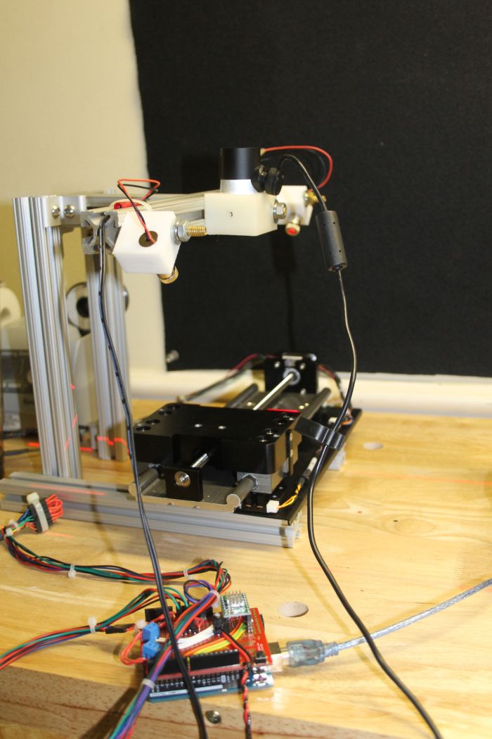 This is useful for making devices like the Kinect appear like a laser scanner for 2D-based algorithms (e.g. laser-based SLAM).
- Author: Tang Tiong Yew
- License: BSD
- Source: git https://github.com/robotictang/eddiebot.git (branch: master)
perception_pcl: pcl_conversions | pcl_msgs | pcl_ros | pointcloud_to_laserscan
Released
Documented
Converts a 3D Point Cloud into a 2D laser scan. This is useful for making devices like the Kinect appear like a laser scanner for 2D-based algorithms (e.g. laser-based SLAM).
- Maintainer status: maintained
- Maintainer: Paul Bovbel <paul AT bovbel DOT com>
- Author: Tully Foote
- License: BSD
- Bug / feature tracker: https://github.com/ros-perception/perception_pcl/issues
- Source: git https://github.com/ros-perception/perception_pcl.git (branch: hydro-devel)
perception_pcl: pcl_conversions | pcl_msgs | pcl_ros | pointcloud_to_laserscan
Released
Documented
Converts a 3D Point Cloud into a 2D laser scan.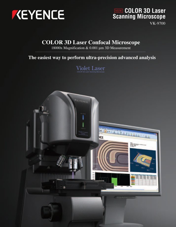 This is useful for making devices like the Kinect appear like a laser scanner for 2D-based algorithms (e.g. laser-based SLAM).
- Maintainer status: maintained
- Maintainer: Paul Bovbel <paul AT bovbel DOT com>
- Author: Paul Bovbel <paul AT bovbel DOT com>, Tully Foote
- License: BSD
- Bug / feature tracker: https://github.com/ros-perception/perception_pcl/issues
- Source: git https://github.com/ros-perception/pointcloud_to_laserscan.git (branch: indigo-devel)
Released
Documented
Converts a 3D Point Cloud into a 2D laser scan. This is useful for making devices like the Kinect appear like a laser scanner for 2D-based algorithms (e.g. laser-based SLAM).
- Maintainer status: maintained
- Maintainer: Paul Bovbel <paul AT bovbel DOT com>
- Author: Paul Bovbel <paul AT bovbel DOT com>, Tully Foote
- License: BSD
- Bug / feature tracker: https://github.com/ros-perception/perception_pcl/issues
- Source: git https://github.
 com/ros-perception/pointcloud_to_laserscan.git (branch: indigo-devel)
Released
Documented
Converts a 3D Point Cloud into a 2D laser scan. This is useful for making devices like the Kinect appear like a laser scanner for 2D-based algorithms (e.g. laser-based SLAM).
- Maintainer status: maintained
- Maintainer: Paul Bovbel <paul AT bovbel DOT com>
- Author: Paul Bovbel <paul AT bovbel DOT com>, Tully Foote
- License: BSD
- Bug / feature tracker: https://github.com/ros-perception/perception_pcl/issues
- Source: git https://github.com/ros-perception/pointcloud_to_laserscan.git (branch: indigo-devel)
Released
Documented
Converts a 3D Point Cloud into a 2D laser scan. This is useful for making devices like the Kinect appear like a laser scanner for 2D-based algorithms (e.g. laser-based SLAM).
- Maintainer status: maintained
- Maintainer: Paul Bovbel <paul AT bovbel DOT com>
- Author: Paul Bovbel <paul AT bovbel DOT com>, Tully Foote
- License: BSD
- Bug / feature tracker: https://github.
 com/ros-perception/perception_pcl/issues
 - Source: git https://github.com/ros-perception/pointcloud_to_laserscan.git (branch: indigo-devel)
Released
Documented
Converts a 3D Point Cloud into a 2D laser scan. This is useful for making devices like the Kinect appear like a laser scanner for 2D-based algorithms (e.g. laser-based SLAM).
- Maintainer status: maintained
- Maintainer: Paul Bovbel <paul AT bovbel DOT com>, Michel Hidalgo <michel AT ekumenlabs DOT com>
- Author: Paul Bovbel <paul AT bovbel DOT com>, Tully Foote
- License: BSD
- Bug / feature tracker: https://github.com/ros-perception/perception_pcl/issues
- Source: git https://github.com/ros-perception/pointcloud_to_laserscan.git (branch: lunar-devel)
Released
Documented
Converts a 3D Point Cloud into a 2D laser scan. This is useful for making devices like the Kinect appear like a laser scanner for 2D-based algorithms (e. g. laser-based SLAM).
- Maintainer status: maintained
- Maintainer: Paul Bovbel <paul AT bovbel DOT com>, Michel Hidalgo <michel AT ekumenlabs DOT com>
- Author: Paul Bovbel <paul AT bovbel DOT com>, Tully Foote
- License: BSD
- Bug / feature tracker: https://github.com/ros-perception/perception_pcl/issues
- Source: git https://github.com/ros-perception/pointcloud_to_laserscan.git (branch: lunar-devel)
Contents
- Node
- pointcloud_to_laserscan_node
- Subscribed Topics
- Published Topics
- Parameters
- pointcloud_to_laserscan_node
- Nodelet
If you're trying to create a virtual laserscan from your RGBD device, and your sensor is forward-facing, you'll find depthimage_to_laserscan will be much more straightforward and efficient since it operates on image data instead of bulky pointclouds. However, if your sensor is angled, or you have some other esoteric use case, you may find this node to be very helpful!
Please check the FAQ for common problems, or open an issue if still unsolved.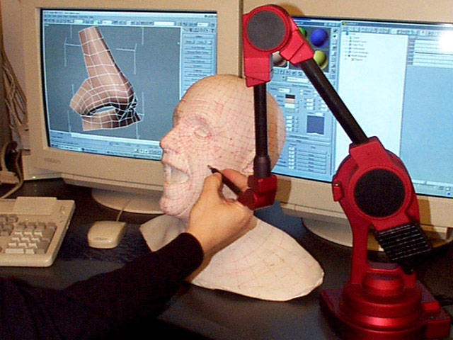
Node
pointcloud_to_laserscan_node
pointcloud_to_laserscan_nodetakes a point cloud and generates a 2D laser scan based on the provided parameters.
Subscribed Topics
cloud_in(sensor_msgs/PointCloud2)
- The input point cloud.
Published Topics
scan(sensor_msgs/LaserScan)
- The output laser scan.
Parameters
~min_height(
double, default: 0.0)
- The minimum height to sample in the point cloud in meters.
(
double, default: 1.0)
- The maximum height to sample in the point cloud in meters.
(
double, default: -π/2)
- The minimum scan angle in radians.

(
double, default: π/2)
- The maximum scan angle in radians.
(
double, default: π/360)
- Resolution of laser scan in radians per ray.
(
double, default: 1.0/30.0)
- The scan rate in seconds.
(
double, default: 0.45)
- The minimum ranges to return in meters.
(
double, default: 4.0)
- The maximum ranges to return in meters.
(
str, default: none)
- If provided, transform the pointcloud into this frame before converting to a laser scan.
 Otherwise, laser scan will be generated in the same frame as the input point cloud.
(
int, default: 1)
- Number of threads to use for processing pointclouds. If 0, automatically detect number of cores and use the equivalent number of threads. Input queue size for pointclouds is tied to this parameter. In nodelet form, number of threads is capped by the nodelet manager configuration.
(
boolean, default: true)
- If disabled, report infinite range (no obstacle) as range_max + 1. Otherwise report infinite range as +inf. Associated with the inf_is_valid parameter for costmap_2d obstacle layers.
Nodelet
Same API as node, available as pointcloud_to_laserscan/pointcloud_to_laserscan_nodelet.
3D Scanner - frwiki.wiki
The 3D Scanner is a 3D digitizing and acquisition device.
A 3D scanner is a device that analyzes objects or their immediate surroundings to collect precise information about the shape and possibly their appearance (color, texture, etc.). The data collected in this way can then be used to construct 3D synthetic images (digital objects) for various purposes. These devices are widely used in the entertainment industry for movies or video games. Digital 3D images of scanned objects are also used for industrial design, orthosis and prosthesis design, reverse engineering, for quality control (digital storage), or for documentation of cultural objects.
When scanning a 3D object, various technologies can be used; each has its own limitations, benefits and costs. However, some types of objects are still difficult to digitize: for example, devices using optical technologies face many difficulties with shiny, flickering or transparent objects.
However, there are methods to scan shiny objects, for example by coating them with a thin layer of white powder, which will allow more photons to be reflected and reach the scanner's optics.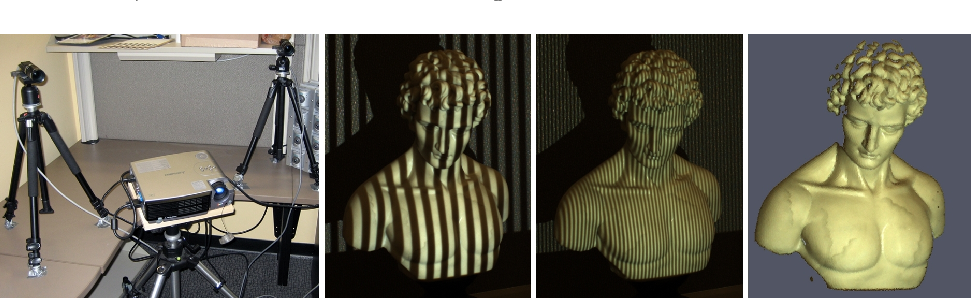 Laser scanners can send trillions of photons to an object and in return receive a small percentage of those photons through the optics they use. The reflectivity of an object in visible light depends on the color of the object, this is the albedo. A white surface will reflect a lot of back light, while a black surface will only reflect a small amount. Transparent objects like glass will only be refracted by light and give false information about three dimensions.
Non-contact 3D scanner
Summary
- 1 principle
- 2 Data collection methods
- 2.1 Contact Scanner
- 2.2 Active proximity scanner
- 2.2.1 Time of flight scanner
- 2.2.2 Phase shift scanner
- 2.2.3 Triangulation Scanner
- 2.2.4 Notes on TOF and triangulation scanners
- 2.2.5 Conoscopic holography
- 2.2.6 Hand scanner
- 2.2.7 Structured Light Scanner
- 2.
 2.8 Modulated Light Scanner
- 2.3 Passive proximity scanner
- 2.3.1 Stereoscopic scanners
- 2.3.2 Silhouette Scanners
- 2.3.3 Scanners requesting user assistance
- 3 Simulation of data collected by the scanner
- 4 Applications
- 4.1 Processing and production of materials
- 4.2 Construction industry and civil engineering
- 4.3 Entertainment
- 4.4 Reverse engineering
- 4.5 Cultural heritage
- 4.5.1 Michelangelo
- 4.5.2 Monticello
- 4.5.3 Cuneiform tablets
- 4.5.4 Model of Rome (Il Plastico)
- 4.6 Health
- 4.6.1 Dental CAD/CAM
- 4.6.2 Computer-aided design and manufacture of orthotics
- 4.7 Quality assurance
- 5 Notes and references
- 6 See also
- 6.1 Related articles
- 6.2 External links
Principle
A 3D scanner typically measures the location of a pattern of points in a coordinate system - a point cloud - on the surface of an object and then extrapolates the shape based on their distribution: this process is called 3D reconstruction . If you analyze the color of each point, you can restore the color of the surface.
There are analogies between a camera and a 3D scanner. Both have a field of view and cannot see what is obscured since both technologies are optical. If the first captures the colors of the surfaces in its field, the other measures its relative position in relation to a sample of surface points.
The generated image is based on a series of data consisting of coordinates that position each of the selected points relative to the 3D scanner. If a spherical coordinate system is used and the scanner is its source, then each point can be identified by coordinates (r, φ, θ). r is the distance from the scanner to the point. φ and θ are the angles formed between a line from the origin to the point under analysis, with two planes passing through the origin, one horizontal and the other vertical. These spherical coordinates allow each point to be located in space relative to the scanner, which is a preliminary and necessary work for digital modeling of a three-dimensional image of an object.
Usually, the data (point coordinates) collected in one pass is not enough for a complete object modeling. The work must be done many times, and even hundreds of times, from different points of view. All collected data must be reinterpreted, placed in a single coordinate system and grouped together. Process , through various measurements before being rethought before the simulation is not known as (o) pipeline 3D scanning .
Data collection methods
3D scanners are divided into two families: requiring contact with an object and others. Non-contact scanners can also be divided into two main categories: active and passive scanners. They themselves are divided into many subcategories in accordance with their technological principle.
Contact scanner
Contact 3D scanners examine an object through physical contact and have good accuracy. However, their use cannot be extended to all types of digitization. Indeed, their principle, based on physical contact, can destroy or change fragile objects. They present a hazard when used with unique or valuable items such as historical objects. Another disadvantage of this technology is its relative slowness compared to other methods. The slow movement of the lever on which the probe is mounted means that the measurements are taken at a low frequency, about 0.1 kilohertz. By comparison, a system using an optical scanner measures between 10 and 500 kilohertz. This type of scanner is used in industry due to its accuracy. In the mechanical industry, for example, coordinate measuring machines. Another example, in the film animation industry, models carved from clay are then digitized in three dimensions.
Active Proximity Scanner
Active scanners emit radiation and detect its reflection to examine an object or environment. Different types of radiation sources are used: light, ultrasonic, or X-ray.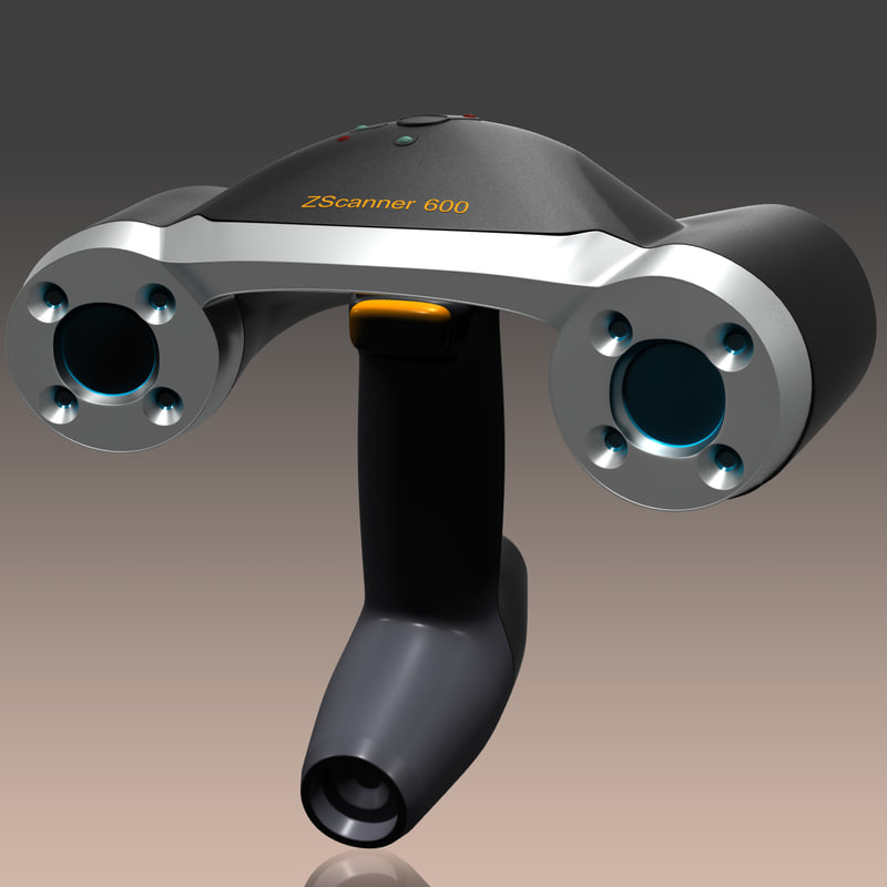
Time of Flight Scanner
This lidar scanner can be used to scan buildings, geological formations, etc. to make a 3D model. His beam can be focused on a very wide horizon: thanks to the horizontal rotation of his head, the mirror directs him vertically. The laser beam is used to measure the distance to the first object that crosses the beam.
The 3D lidar scanner is an active device that uses a laser beam to examine an object. This type of scanner is based on a laser rangefinder, which allows you to calculate the distance to the surface of the object under study by calculating the time required for the reflected laser beam pulse to travel back and forth. Because the speed of light is known, the return time is used to determine the distance traveled by the light, which is twice the distance between the scanner and the surface. If is the return time, then the distance is . Obviously, the accuracy of a time-of-flight scanner depends on the accuracy of the return time measurement, knowing that 3.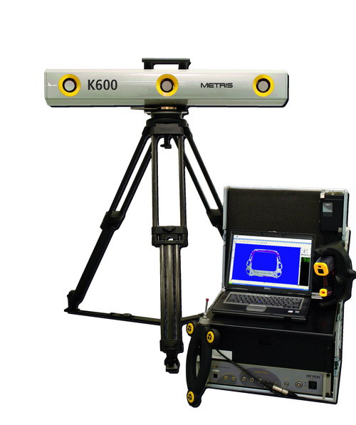 3 picoseconds is roughly the time it takes for light to travel a millimeter. vs {\displaystyle c}t{\displaystyle t}(vs⋅t)/2{\displaystyle (c\cdot t)/2}t{\displaystyle t}
The laser rangefinder only detects one point at a time in the direction it is pointing. To do this, the device scans the entire field of view point by point and must change the direction of view for each measurement. It can be changed by rotating the device itself or by using a system of rotating mirrors. The latter method is used most often because mirrors are lighter and can change direction faster and with greater accuracy. Time-of-flight 3D scanners can measure distances from 10,000 to 100,000 points per second.
Phase shift scanner
Another technology used by laser scanners to measure distances is "phase shift measurement". The scanner emits a laser beam that, upon contact with an object, is reflected back into the laser scanner. The laser wavelength depends on the supplier. The scanner mirror reflects the laser beam vertically towards the same object. The vertical angle is encoded along with the distance measurement.
Laser scanner rotates 360° horizontally. The horizontal angle is calculated simultaneously with the distance measurement. Distance and vertical and horizontal angles give polar coordinates (δ, α, β) which are converted to Cartesian coordinates (x, y, z). Some laser scanners use phase shift measurement technology to measure distance from a surface. The device emits an infrared laser beam that is reflected back to the scanner. This calculates the distance to the nearest millimeter by analyzing the phase shift between the emitted beam and the received beam. A laser beam of a known sinusoidal wave is scattered by a laser source. This is the "radiated light". Part of the laser beam is reflected from the target to the source. Then we talk about "reverse light". The phase of this "reflected light" is compared with the phase of the known emitted light to determine the "prehistory of the emitted light". The difference between the two peaks is called "phase shift". The resulting phase shift corresponds to 2π x time of flight x modulation frequency. Phase shift scanners are generally faster and more accurate than TOF 3D laser scanners, but they have a shorter range.
Triangulation Scanner
How the detector works using laser triangulation. Two positions of the object are shown.
The triangulation laser scanner is an active scanner that also uses laser light to explore the environment. It points at an object with a beam, similar to a beam while flying, and uses a camera to locate the point. Depending on the distance to the surface, the dot appears at a different location in the device's field of view. This method is called triangulation because the laser dot, camera and laser emitter form a triangle. The length of one side of the triangle, the distance between the camera and the laser emitter are known. The side angle of the laser emitter is also known. The angle of the camera side can be determined by looking at the location of the laser dot in the camera's field of view.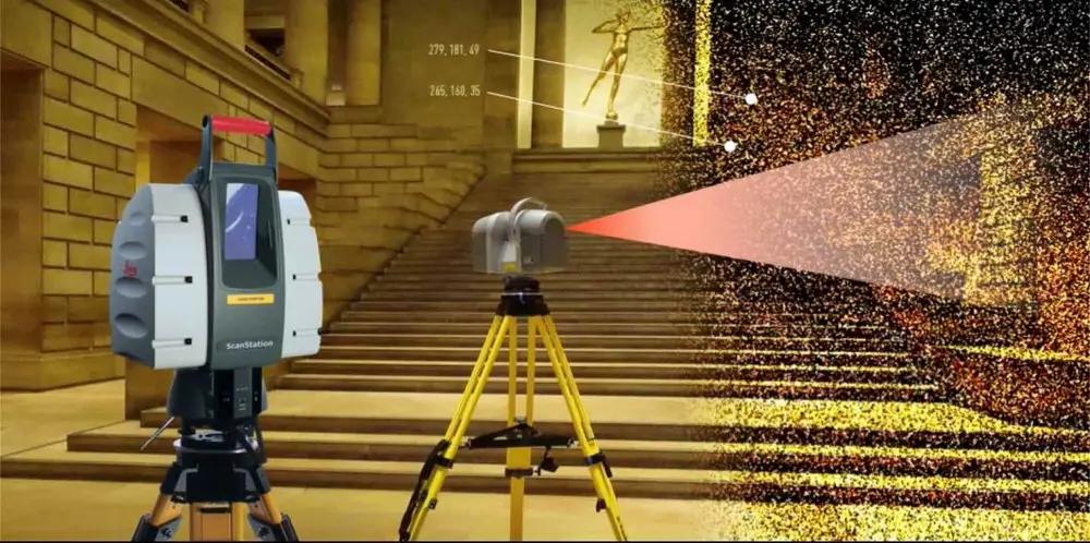 These three data define the shape and dimensions of the triangle and give the position of the laser dot. In most cases, a laser streak, rather than a dot, scans the object to speed up the capture process. The National Research Council of Canada was one of the first institutes to develop triangulation based on scanner technology at 1978 year.
Notes on TOF and Triangulation Scanners
Triangulation or TOF rangefinders have their own strengths and weaknesses that make them suitable for a variety of situations. The advantage of the time-of-flight rangefinder lies in its long range, which makes it possible to work over long distances of the order of several kilometers. These scanners are suitable for scanning large structures such as buildings or geographic features. Their weakness is in their inaccuracy. Due to the very high speed of light, it is difficult to calculate the round trip time of the signal, and the measurement accuracy is relatively low, on the order of a millimeter.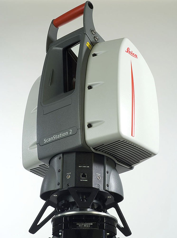 In contrast, triangulation scanners have a small range, a few meters, but their accuracy is relatively good, on the order of tenths of a millimeter.
The accuracy of TOF scanners can be lost when the pulse hits the edge of an object, so the information returned comes from two different locations for the same transmission. These coordinates relative to the position of the point scanner hitting the edge will be calculated from the average and its location will be erroneous. When using a high resolution scanner on an object, the edge is more likely to hit the beam and the corresponding data will show noise just beyond those edges. A smaller scanner beam width will help solve this problem, but will be limited in terms of range as the width will increase with distance. The software can also help determine which of the two beams is hitting the first and eliminate the second.
At 10,000 readings per second, a low resolution scanner pass can take less than a second, but high resolution scanners requiring millions of samples can take several minutes for high resolution scanners.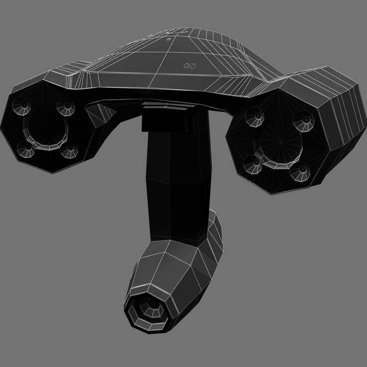 The consequence of this is the distortion associated with movement. Because each point is measured at a different time, even the slightest movement of an object or scanner will skew the collected data. Generally, both the object and the scanner should be placed on a stable stand and vibrations should be limited. Using these devices to scan moving objects is difficult.
Research has recently been done to compensate for distortion due to low vibrations.
During scanning at a given position and regardless of the duration, slight device movement may be caused by temperature changes. If the scanner is mounted on a tripod and a bright sun is shining on one of its legs, it will expand and slowly distort the scanned data from side to side. Some laser scanners have a built-in level compensator to counteract any movement of the scanner during operation.
Conoscopic Holography
In a conoscopic system, a laser beam is projected onto a surface, then the reflection through the same beam passes through a birefringent crystal and is sent to a CDD sensor. The frequency of the diffraction patterns can be analyzed and allows you to determine the distance from this surface. The main advantage of conoscopic holography is collinearity, i.e. one beam is needed to perform the measurement (to and fro), which allows, for example, to measure the depth of a finely drilled hole, which is not possible with triangulation.
Handheld scanner
Handheld laser scanners create 3D images based on the triangulation principle described above: a point or laser line is projected onto an object using a handheld device and a sensor (usually a CDD sensor or position sensitive device ) measures the distance from the surface .
Positions are recorded relative to the internal coordinate system, and the scanner itself, which is in motion, then its position must be measured. The position can be determined by the scanner using characteristic landmarks on the scanned surface (usually reflective adhesive tapes) or using an external registration method. The device responsible for this location is a 3D measuring machine equipped with a built-in camera (to determine the orientation of the scanner) or a photogrammetry device using three or more cameras allowing six degrees freedom scanner. Both methods typically use infrared LEDs built into the scanner that are sensed by the camera(s) through filters that allow them to be seen despite ambient light.
Information is collected by a computer and recorded as coordinates of points located in three-dimensional space, with the help of computer processing, they can be transformed by triangulation into a canvas and then into a computer model, most often in the form of NURBS surfaces. Handheld laser scanners can combine this data with passive visible light receivers that record textures and colors to reconstruct (see reverse engineering) a complete 3D model of the model.
David LaserScanner software, which was used to convert a digital camera or webcam and laser into a handheld 3D scanner at a very low cost, was purchased by Hewlett Packard in 2016.
Structured Light Scanner
3D structured light scanners project a pattern of light onto an object and observe its distortion. The pattern can be one or two dimensional.
Consider the example of a line as a one-dimensional pattern. It is projected onto an object using an LCD or laser projector. The camera, slightly offset from the projector, captures its possible deformation. A method similar to triangulation is used to calculate the distance and hence the position of the points representing it. The template scans the field of view to record distance information one tape at a time.
Let's now take a grid or stripe pattern as an example. A camera is used to record the deformations, and a complex computer program is used to calculate the distances to the points that make up this pattern. Complexity comes from ambiguity. Let's consider a group of vertical bands covering the object horizontally. In the simplest case, the analysis is based on the assumption that the sequence of visible fringes from left to right matches the sequence of the projected laser image, so that the image of the leftmost fringe is indeed the first laser projection, the next one is the second, and so on. However, in the case of non-trivial targets with holes, occlusions, rapid depth changes, the order is no longer necessarily checked, since the fringes are often masked and may even appear in a different order, resulting in ambiguous laser fringes. . This particular problem has been recently solved by a technological advance called "Multi-Laser Triangulation (MLT)" (en: Multi-Laser Triangulation). Structured light 3D scanning is still an active area of research due to which many publications are published every year.
The strength of structured light 3D scanners is their speed. Instead of scanning one point at a time, they scan the entire field of view at once. This limits or eliminates distortion problems associated with motion. Existing systems are capable of scanning moving objects in real time. Recently, Song Zhang and Peisen Huang of Stony Brook University have developed an operational scanner using digital stripe projection and phase modulation (another structured light method).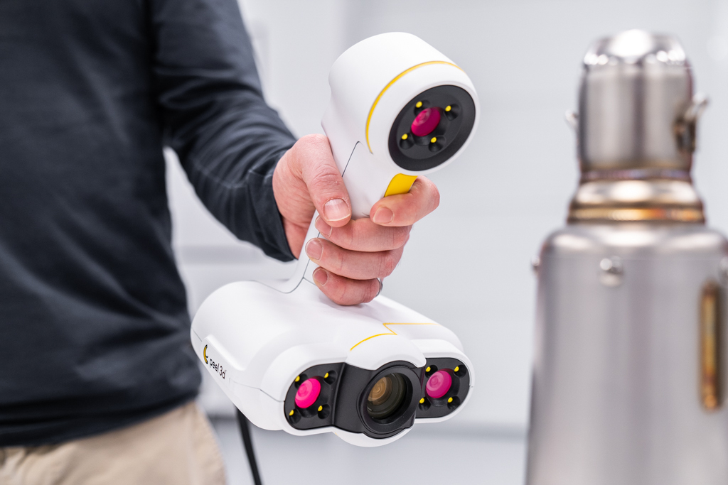 This system is capable of capturing, restoring and restoring the details of objects that deform over time (such as facial expressions) at 40 frames per second.
Modulated Light Scanner
Modulated Light 3D scanners illuminate an object using varying light (see Spatial Light Modulator). Typically, a light source has a cycle whose amplitude describes a sinusoidal pattern. The camera detects the reflected light, measures the amount of change, and determines how far the light has traveled. The modulated light also allows the scanner to ignore a light source other than the laser, so there is no interference.
Passive proximity scanner
Non-radiative passive non-contact scanners based on the detection of reflected external radiation. Most scanners of this type detect visible light because it is immediately available. You can also use other types of radiation, such as infrared. Passive methods can be inexpensive, since in most cases they do not require a special emission device.
Stereoscopic scanners
Stereoscopic systems typically use two video cameras placed a short distance apart and pointing at the same scene. By analyzing small differences between the images of two devices, the distance to each point in the image can be determined. This method is based on human stereoscopic vision.
Silhouette Scanners
These types of 3D scanners use outlines created from a series of photographs taken around a 3D object against a contrasting background. These silhouettes are separated from the background and assembled with each other at the location of the camera's axis of rotation to form a "visual skin" close to the object. With this type of technique, all kinds of concavity in an object, such as inside a bowl, are not detected.
Scanners asking for user assistance
There are other methods based on user-assisted detection and identification of the characteristics and shapes of a series of different images of an object, which allow one to build its approximation.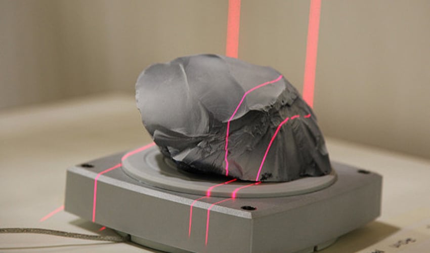 This type of technique is useful for quickly zooming in on an object that consists of simple shapes, such as buildings. This can be done in various commercial programs such as iModeller, D-Sculptor or RealViz-ImageModeler.
These types of 3D scanners are based on the principles of photogrammetry. In a sense, they use a similar methodology to panoramic photography, except instead of taking images from a fixed point to create a panorama, a series of images are taken from different points on a fixed object in order to reproduce it.
Simulation of data collected by the scanner
In a cloud of points obtained using 3D scanners, often cannot be used as is. Most applications do not directly use them, but instead use 3D modeling. This implies, for example, in the context of 3D polygonal modeling, defining and connecting adjacent points to create a continuous surface. A large number of algorithms are available for this work (for example, photo model, image model).
Applications
Material handling and production
Laser scanning is a method of taking a sample from a surface using laser technology.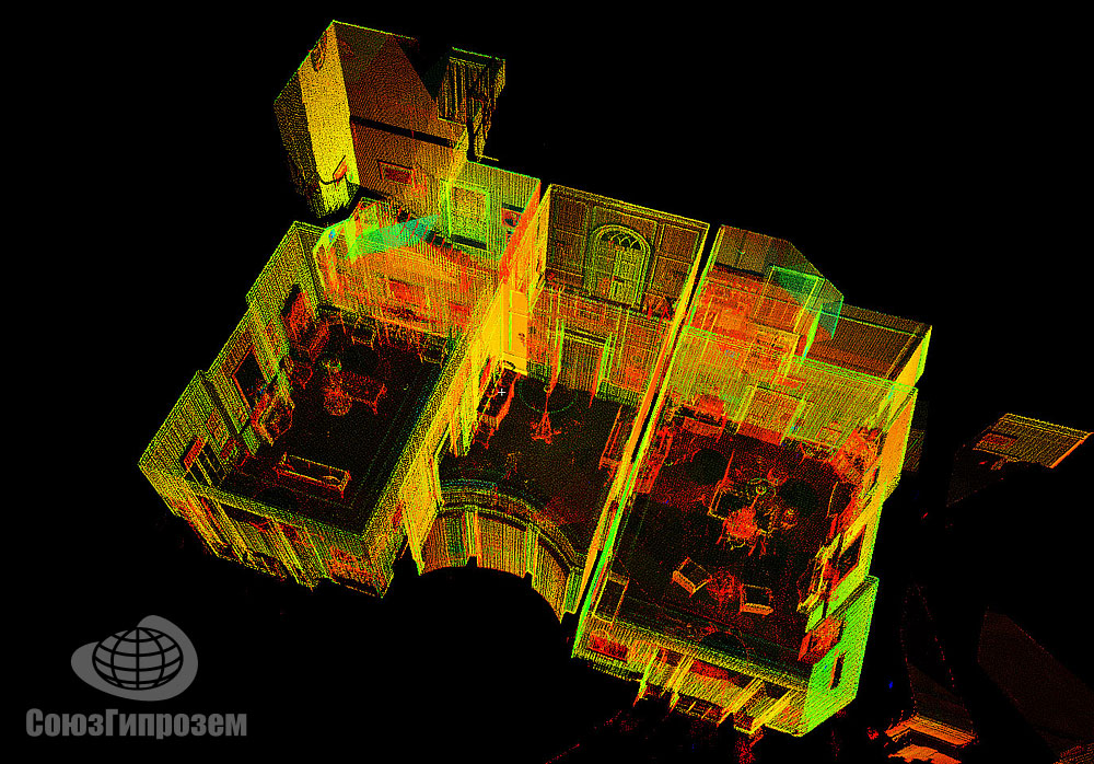 There are several areas of application that differ from each other mainly in the power of the lasers used and their results. Low power lasers are used when the scanned surface cannot be changed, i.e. it needs to be digitized. The confocals lasers and 3D allows you to get information about scanned surfaces.
Depending on the power of the laser, its effect on workpieces varies: lower powers are used for laser engraving, in which the material is partially removed. At higher power, the material becomes liquid and laser welding can be performed, and if the power is sufficient to completely remove the material, laser cutting becomes possible.
3D modeling is also used for rapid prototyping, when, for example, a part is created using the selective laser sintering method (selective laser sintering without liquid phase).
The principle used for all these applications is always the same: software running on a PC or embedded system that controls the entire process is connected to the scanner card.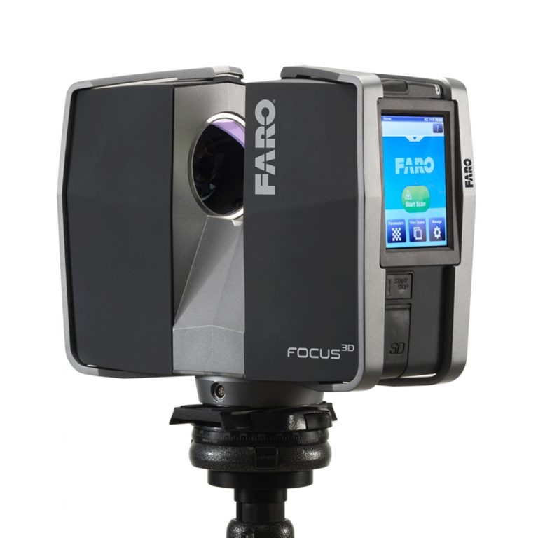 This card converts the received vector information into motion data, which is transmitted to the scanner head. The scanner head consists of two mirrors capable of deflecting the laser beam at a level (X and Y coordinates). The third measurement - if necessary - is performed by special optics that can move the laser focus along the depth axis (Z axis).
The third dimension is needed for special applications such as rapid prototyping where an object is built up layer by layer, or glass engraving where the laser has to change the material more or less profoundly. In these cases, it is important that the laser has as precise a focus as possible.
For advanced applications or high throughput production, scan systems with more than one scan head are used. To do this, the software must precisely control what is being done: it is not possible for all available heads to do the same engraving job at the same time in order to finish as quickly as possible, or the heads cannot do the same task in parallel with each other. performing each piece of work as part of a larger work.
Structured light projection systems are also used to measure the thickness of solar cells, allowing the calculation of flux voltages in excess of the threshold value of 2000 plates per hour.
Construction industry and civil engineering
- As built documentation and architectural drawing (exterior - interior)
- Masonry and structural analysis
- Plans for bridges, industrial plants and monuments.
- Technical Documentation of Historic Sites.
- 3D modeling of the site and its layout.
- Quality control.
- Quantitative review.
- Resuming a plan from an existing one.
- Generating a pre-existing state/shape model to detect structural changes after very strong constraints (e.g. earthquake, vehicle impact, fire, mechanical, etc.).
- Monitoring of structural deformations, section over time (4D)
- Creation of GIS ( Geographic Information System ) and geomatic maps .
- BIM building modeling
Entertainment
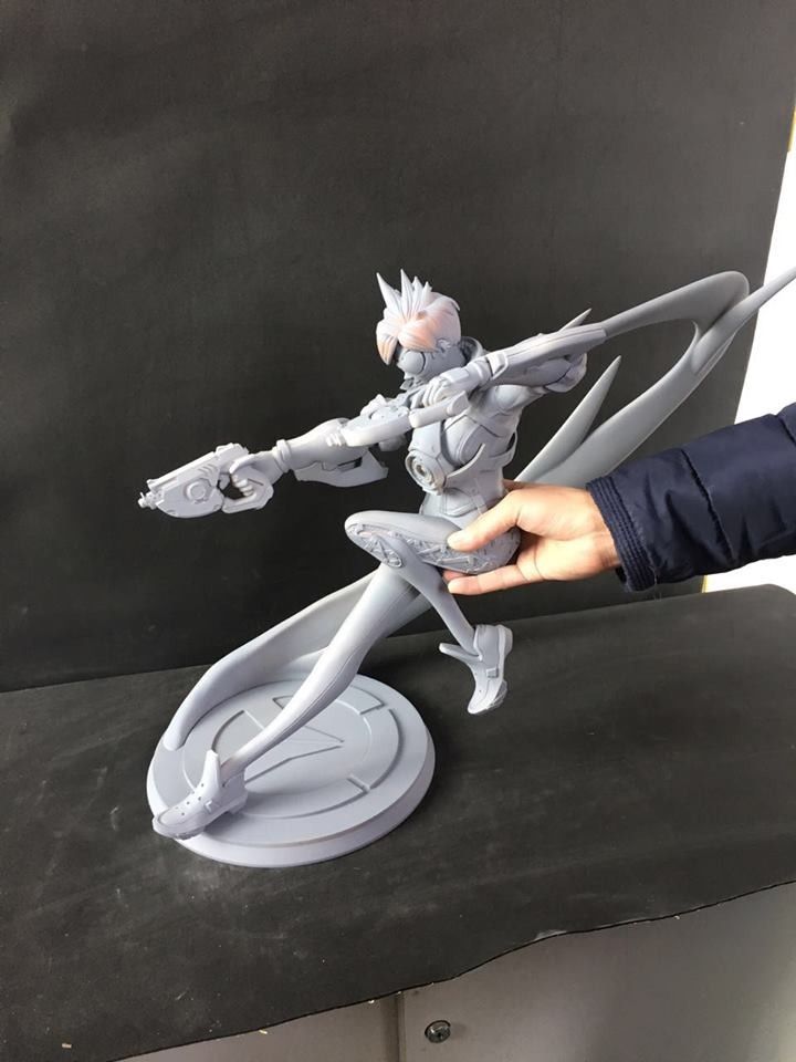
3D scanners are used in the entertainment industry to create 3D models of movies and video games. If a physical representation of the model exists, it is much faster to scan it than manually create it with 3D modeling software. Often artists sculpt a physical model and scan it rather than create a digital image directly on a computer.
Disassemble the mechanism in order to understand how it works
Reverse engineering of a mechanical component requires an accurate digital model of the object to be reproduced. The model can be more accurately represented by a mesh , flat or curved NURBS surface, or ideally a computer-aided design (CAD) solid model rather than a group of points. A 3D scanner can be used to scan free-form or progressively shaped components such as prisms, while a coordinate measuring machine is typically only used to measure prisms with very pronounced characteristics. These coordinates are then processed by specialized reverse engineering software to create a model.
Cultural heritage
Numerous research projects have been undertaken to scan historical sites and objects for documentary and analytical purposes.
The combined use of 3D scanning and 3D printing allows the reproduction of real objects without the use of traditional plaster casting methods, which can often be dangerous when used on fragile or archaeological sites.
Michelangelo
B 19In 99, two separate research groups began scanning Michelangelo's statues. Stanford University with a team led by Mark Leva used Cyberware's custom built-in laser triangulation scanner to preserve Michelangelo's statues in Florence, including David, in Prigioni and four statues from one of the Medici Chapels (New Sacristy). The scans have a resolution on the order of one point every 0.25 mm ², high enough to see the marks of Michelangelo's chisel. These detailed scans yield a very large amount of data (over 32 gigabits) and took five months to process. Around the same time, an IBM research team, led by H. Raschmeier and F. Bernardini, was scanning Florence Pietà, recording details of shapes and colors.
Monticello
In 2002, David Lübcke et al. scanned Thomas Jefferson's Monticello house with a commercial flight time scanner: DeltaSphere 3000. The data was subsequently combined with colors from digital photographs to create a virtual Monticello house. Jefferson's virtual office was exhibited at the Museum of New Orleans in 2003. This exhibition imitated an open window in the Jefferson Library. It was a projection on the wall, which was viewed by the viewer wearing stereoscopic glasses. Glasses equipped with polarizing filters, combined with projectors that emit polarized light, created a three-dimensional effect. The tracking equipment for the glasses made it possible to adapt the viewer's movement projection, creating the illusion that the screen was actually a hole in the wall overlooking the library.
cuneiform tablets
In 2003, Subodh Kumar et al. began 3D scanning ancient cuneiform tablets. And again, a laser triangulation scanner was used. Tablets were scanned in a regular grid with a resolution of 0.025 mm .
Model of Rome (Il Plastico)
In 2005, Gabriele Guidi et al. scanned Il Plastico, a model of ancient Rome by Italo Gismondi. Neither triangulation nor the time-of-flight method was sufficient to achieve the goals of the project because the model was large and contained fine details. However, they found that a modulated light scanner could scan a model-sized object with the desired accuracy. However, the scanner was assisted by another, using the triangulation of part of the object.
Health
Dental CAD/CAM
Many dental chair side CAD/CAM systems and CAD/CAM systems for dental laboratories use 3D scanning techniques to record the surface of preparations ( in vivo or in vitro ), to create a digital model with using CAD software and for computer assisted tooth reconstruction.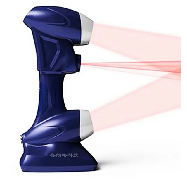 Auxiliary production technologies (for example, a CNC milling machine or a 3D printer). Dentist chair side systems are designed to facilitate 3D preparation registration in vivo and enable reconstruction (using a crown, conservative dentistry or veneer).
Computer-aided design and manufacturing of orthopedic products
Many podiatrists also use scanners to record the patient's form. This technique gradually replaces the tedious plaster molding. CAD/CAM software is used to design and fabricate orthoses or prostheses.
Quality assurance
The digitization of existing objects is of paramount importance in various applications. This method is mainly used in the field of quality control to measure the accuracy of geometric dimensions. Process industries such as assembly are complex, highly automated and based on CAD (Computer Aided Design). The problem is that the same level of automation is required for quality assurance. For example, assembling a modern car is a very complex task, essentially consisting of assembling many elements together at the very end of a production line.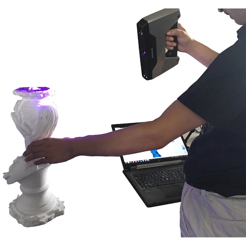 Optimal performance of this process is guaranteed by quality assurance systems. In particular, the geometry of metal parts needs to be checked to make sure they are the right size, fit together, and ultimately perform well.
In highly automated processes, the obtained geometric measurements are transferred to machines that create the desired object. Due to inaccuracies and abrasion, the result may differ from the original digital model. To automate capture and evaluate these deviations, the created object must also be digitized. For this, 3D scanners are used, which generate sample coordinates of points on its surface for comparison with the model. Tactile and optical scanners are used to obtain three-dimensional measurements. The small size and simple design of the frictionless second provides flexibility in use and is increasingly replacing the proven reliability of the touch scanner.
Notes and links
- ↑ (in) Fausto Bernardini, Holly E.
 Roy Meyer, Canadian Scientist: Invention and Innovation from the National Research Council of Canada , Vancouver: Raincoast Books, 1999.
 - ↑ François Blais, Michel Picard, Guy Godin, "Accurate 3D Capture of Freely Moving Objects", Proceedings. 2nd International Symposium on 3D Data Processing, Visualization and Communication, 2004, pp. 422-429.
- ↑ (in) " HP David's 3D Scanning Solutions" on wirthconsulting.org, (accessed December 8, 2016)
- ↑ (in) Song Zhang, Huang Peisen, High Resolution Real Time 3D Shape Measurement , Optical Engineering, 2006, p.123601. [ read online ]
- ↑ (in) David Young, "Stereoscopic Vision and Perspective Projection" Tutorial File , University of Sussex, Sussex, Computer Vision, January 1994 [read online]
- ↑ (in) WJ Walecki, F.
 Szondy and MM Hilali, “Fast inline metrology. Surface topography enabling stress calculation for the production of solar cells with a capacity exceeding 2000 wafers per hour”, 2008. Izmer. sci. Technol. 19 025302 (6pp) DOI: 10.1088 / 0957-0233 / 19/2/025302
 - ↑ (en) « Anna Hidalgo 3D scanned during Futur en Seine 2013 ", on Shapelize
- ↑ (in) Mark Levoy, Jeremy Ginsberg, Jonathan Shade, Duane Fulk, Kari Pulli, Brian Kerless Shimon Rusinkiewicz David Koller, Lucas Pereira, Matt Ginzton, Sean Anderson, James Davis, Digital Michelangelo Project: 3D Scanning of Large Statues , Proceedings of the 27th Annual Conference on Computer Graphics and Interactive Methods, 2000, pp. 131-144. [ read online ]
- ↑ David Lübke, Christopher Lutz, Rui Wang and Cliff Woolley, www.
 Subod Kumar, Dean Snyder, Donald Duncan, Jonathan Cohen, Jerry Cooper, Digital Preservation of Ancient Cuneiform Tablets with 3D Scanning , Fourth International Conference on 3D Digital Imaging and Modeling, 2003, p.
 - ↑ (in) Gabriele Guidi, Laura Micoli, Michele Russo, Bernard Frischer, Monica De Simone, Alessandro Spinetti, Luca Carosso, 3D Digitization of a Wide Model of Imperial Rome , Fifth International Conference on 3D Digital Imaging and Modeling, 2005 pp. 565-572.
See Also
Related Articles
- Real Time 3D
- Camera flight time
- 3D infographic
- 3D modeling software
- 3D motors
- Stereo vision
External links
scopes and overview of models / Sudo Null IT News
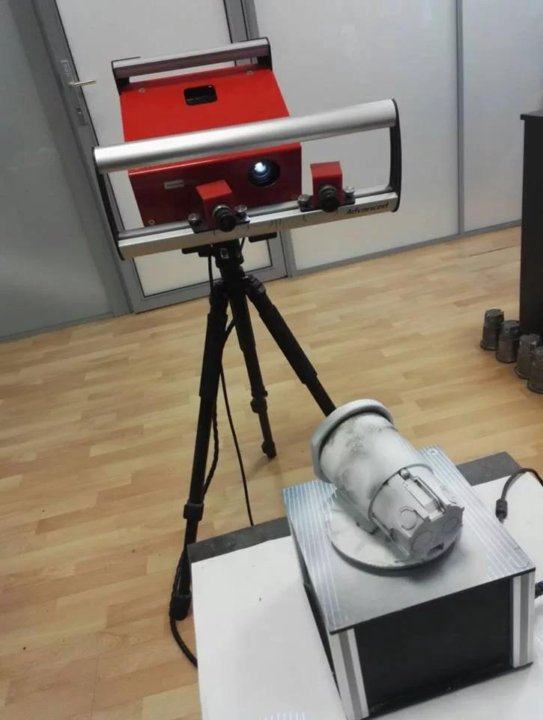
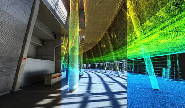
3D laser scanning - creating a digital model of a physical body using a laser beam.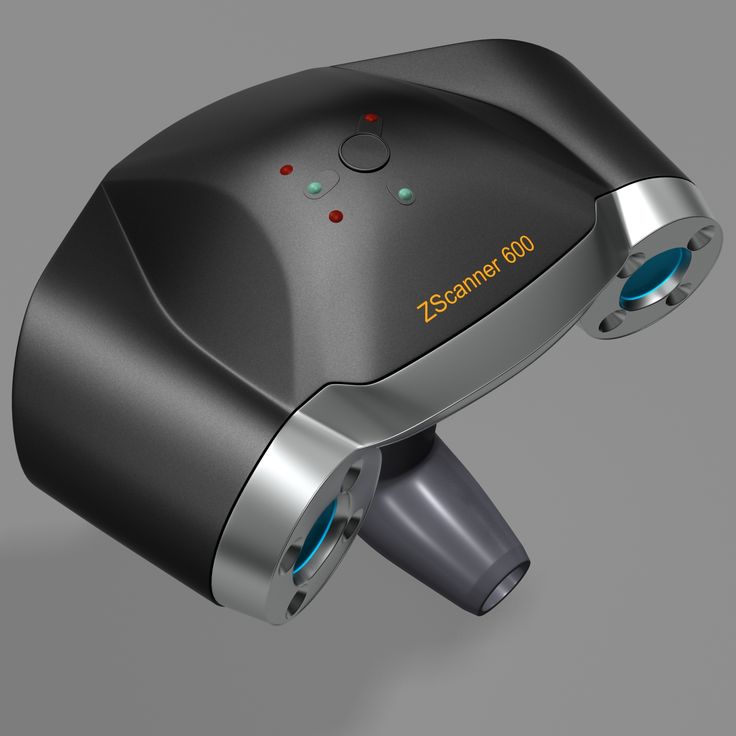 The technology is non-contact, works at close and long distances, eliminates damage to objects during scanning. The principle of operation of 3D laser scanners: a directed laser beam is reflected from the surface of an object, forming a cloud of points. Each point has its own coordinates in space. The software identifies them and creates a finished 3D digital model based on this data.
From the overview you will find out where laser scanning is used and what equipment is used to solve related problems.
Purpose of laser scanners
Source: newequipment.com
In comparison with traditional methods of measurement, laser scanners have an important advantage - they can digitize objects with complex surfaces and work in hard-to-reach places for humans. The main areas of application of devices are input and output quality control in production, inspection of working devices in order to prevent and eliminate defects, reverse engineering and other areas.
Construction, renovation and renovation of objects
Source: ellisdon.com
During the preparation of the building project, it is necessary to evaluate the features of the site and the cost of the forthcoming works. With the help of 3D laser scanners, a landscape model is created, on the basis of which further work is carried out. During the construction process, intermediate control of the geometry of future buildings is required: walls, corners, openings, etc. Laser scanning copes with this task more accurately and faster than conventional measuring technologies.
The basis for an exterior or interior renovation is often an accurate digital model, on the basis of which changes and additions to the current interior or exterior are planned. Laser scanners are also indispensable in this area.
Road networks and transport
Source: autodesk.com
Laser scanning is becoming an integral part of the planning and creation of urban and suburban road networks, tunnels, pedestrian sections, railways, ports. The technology is used to assess the current state of pavements, plan and estimate the cost of repairs, to obtain models of perennial structures, such as bridges. The equipment is involved in the design, manufacture, repair and tuning of cars, air transport and ships.
Public utilities
Source: 3dscanner.es
With the help of 3D laser scanners, it became possible to quickly digitize and document engineering communications. Scanning significantly saves time during maintenance and reconstruction. The devices work remotely, minimizing the risks of people when working in adverse conditions and in hard-to-reach areas.
Oilfield installations
Source: ramboll.com
Oil production complexes located in the water require constant monitoring of work processes. Objects are regularly exposed to adverse and changeable environmental influences: winds of different strengths and directions, currents, temperature changes, etc.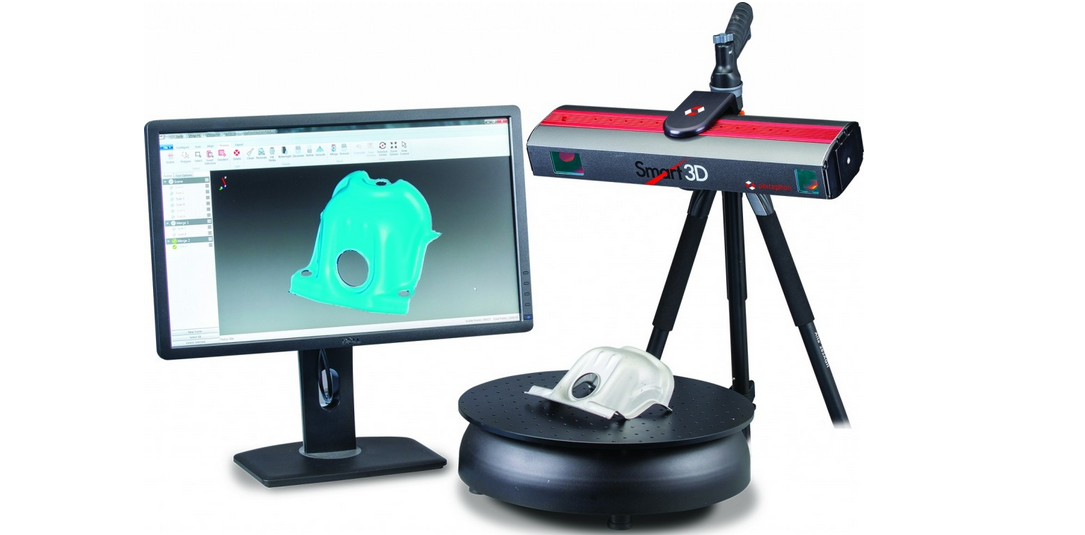 3D laser scanning is becoming an integral part of the inspection of oil production installations. The equipment allows you to quickly identify and fix deformations and other damage, control wear, calculate the timing of scheduled maintenance, and prevent accidents.
Forensic
Source: faro.com
Photographs and manual measurements in investigative processes and forensic examinations are being replaced by 3D laser scanning. The devices create three-dimensional models of scenes of incidents with accurate fixation of the location of objects and the distances between them. The data is used in the process of pre-trial and litigation.
Other applications
Source: news.microsoft.com
3D laser scanners facilitate and optimize workflows in the following areas:
- In cartography and geodesy - when creating terrain plans, maps, geographic information systems (GIS).
- In archeology, in the restoration and preservation of ancient artifacts.
- In paleontology, to create missing parts of excavated skeletons.
- In medicine, including plastic surgery and dentistry.
Overview of models and manufacturers
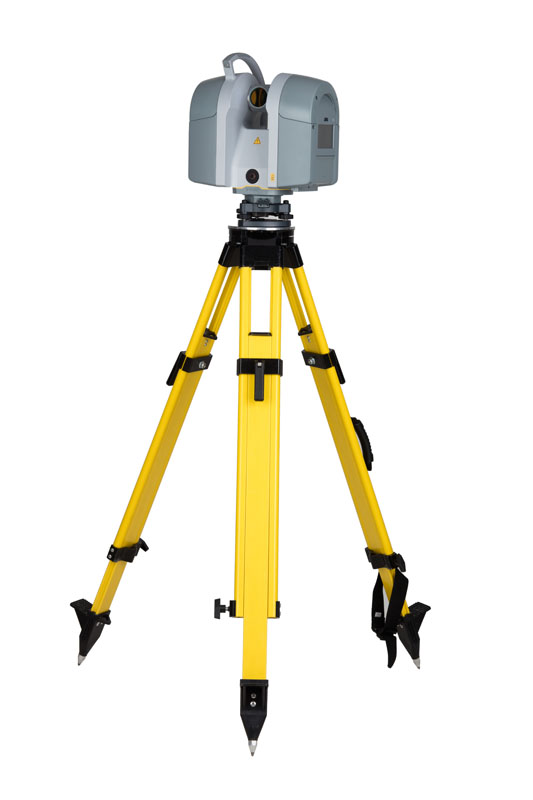
FARO Focus
Source: ifworlddesignguide.com
FARO is one of the popular manufacturers of laser scanning devices. The new Focus3D S-series instruments stand out from other scanners in lightness and compact size, as well as the ability to work in bright sunlight and keep in touch with the location using GPS.
The FOCUS 3D S 150 scanner works at a distance of up to one hundred and fifty meters, with an accuracy of up to ±2000 microns at a maximum distance. The device is used in design, architecture and construction, for digitizing equipment and other objects.
You can learn more about this model on the website.
Source: youtube.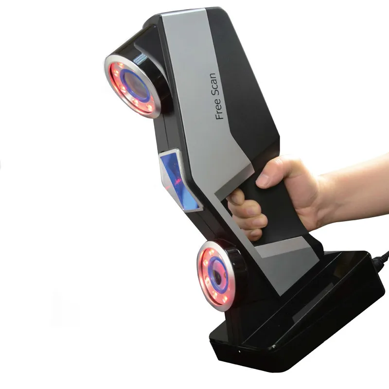 com
com
Focus3D S 350 scans with the same accuracy as the previous device, but the distance to the measurement object is increased to 0.35 km. The device is designed for outdoor use.
Source: kkgeosystem.blogspot.com
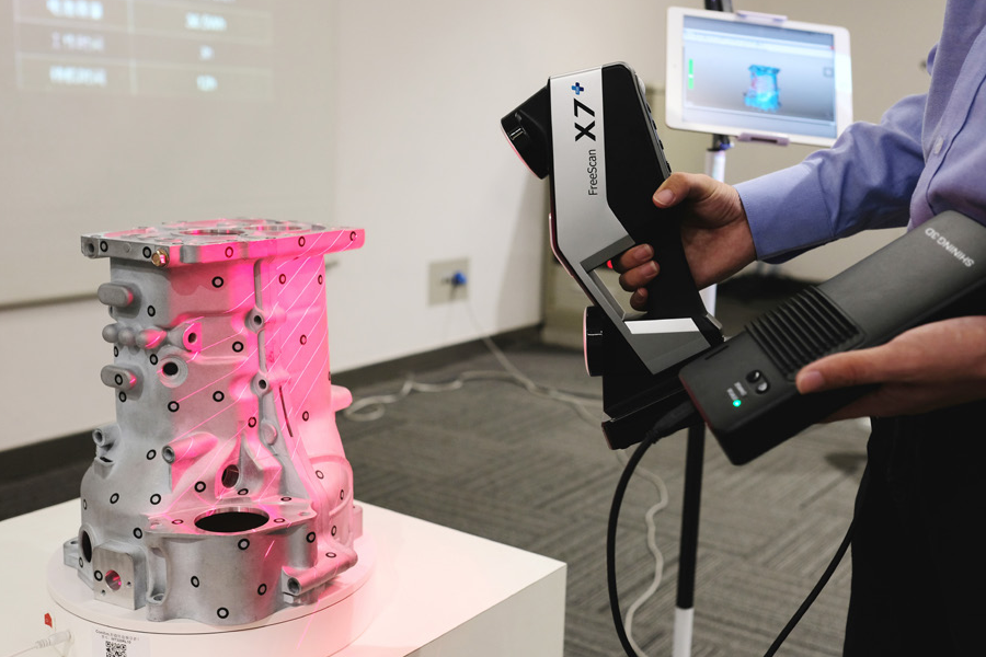
SHINING 3D
Source: shining3d.com
FreeScan is a line of well-known Chinese manufacturer of digital equipment SHINING 3D. These are universal laser handheld 3D scanners FreeScan X5 (X5+), FreeScan X7 (X7+) weighing up to 1 kg, with an excellent set of professional features.
Basic parameters:
Specifications
Creaform
Source: foundry-planet.com
Creaform's SCAN 3D range is characterized by high scanning quality combined with ease of use. Portable laser scanners HandySCAN 3D, MetraSCAN 3D have a clear interface, do not require special skills and complex user training.
Instrument features:
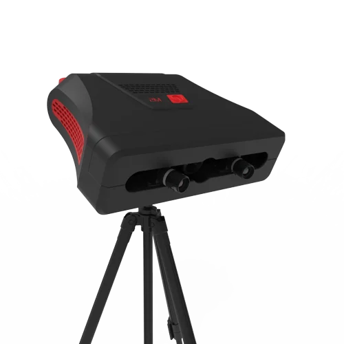
ScanTech
Handheld range
Source: cmmxyz.com
The HandHeld Prince series uses blue and red laser beams to scan large and small objects with high accuracy. Scanners can operate in bright sunlight and low light conditions. Due to its compact size, high speed and detail, the equipment is widely used in reverse engineering, quality inspection, digitization of museum, archaeological and other objects.
Key features:
Composite series
Source: twitter.com
In addition to the dual scan mode, the KSCAN20 is equipped with a photogrammetry system, thanks to which the working area of the device is 2.5 m * 3 m with an accuracy of 35 µm / m.
Blue and red lasers provide high-speed scanning of up to 650,000 measurements per second with a resolution of 0.01 mm.
Key Features:
3D Laser Scanner Applications 9
Source: autodesk.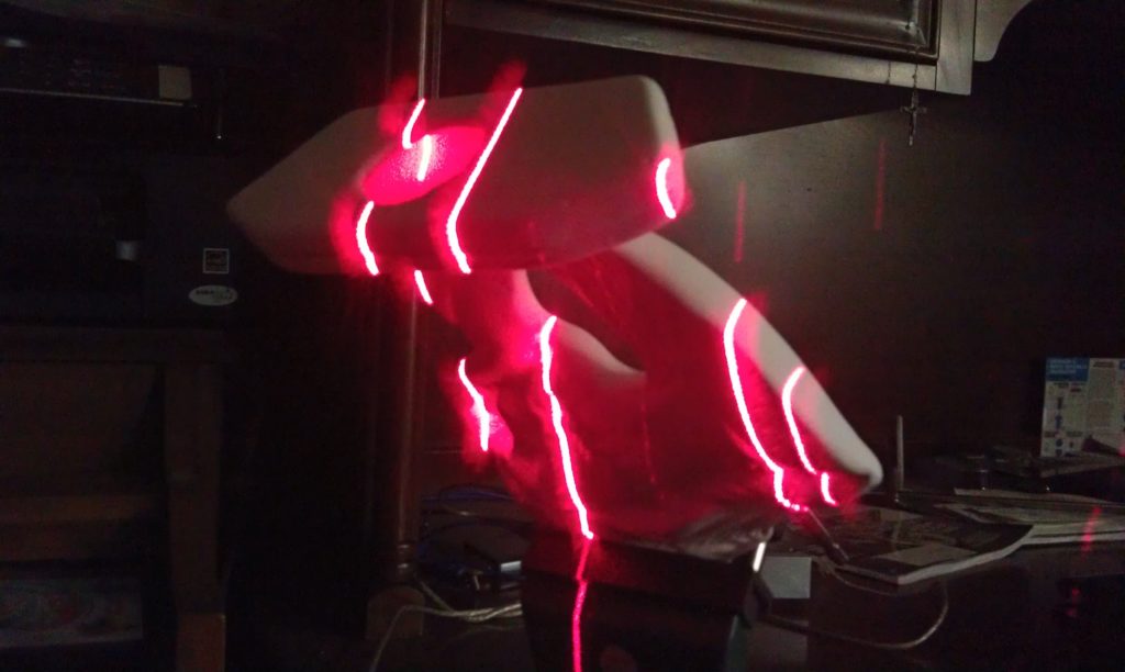 com
com
US construction company Gilbane invested $60,000 in the purchase of a FARO Focus-S 350 laser scanner, software and employee training. At first glance, the amount seems too large for a small-scale firm. But, after making calculations, the company's management came to the conclusion that the investments would pay off in the shortest possible time.
According to Gilbane's director of 3D design, John Tocci Jr., after introducing the expensive new technology, the company began to use the equipment even in areas where it was not originally planned. The specialists managed to save $30,000 for one hour of Focus-S 350 and Autodesk Revit software.
Source: autodesk.com
Building a digital model of air ducts and other systems made it possible to avoid errors during the installation of physical objects, which could take several weeks. The use of FARO Focus in the assembly of plumbing, electrical and mechanical installations helped to optimize costs at all stages of work
Case “Modernization of the building of the University of Miami”
Source: elevar.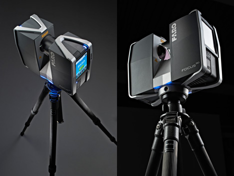 com
com
At the time of the start of work, the architects had drawings made 85 years ago, and a little more than 4.5 thousand square meters of the old building. Using a 3D laser scanner, Gilbane digitized the training areas in one day. The modernization of the load-bearing structures, as well as the main utility systems: plumbing, electrical and ventilation, was based on the data obtained from the scan.
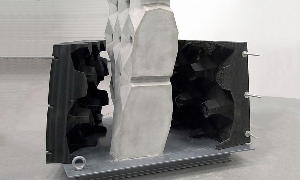
Quality Inspection with ScanTech
Source: 3d-scantech.com
The advantage of metal stamping over forging and casting is that the resulting parts are lighter and thinner. The use of molds gives high accuracy and maximum compliance of the obtained parts with the specified characteristics, but does not completely exclude deviations and deformations. Which, in turn, can lead to difficulties in assembling finished products and reducing product quality. Therefore, constant quality inspection is a necessary part of production.![]()
Understanding the manufacturer's tasks, ScanTech suggested checking the quality of stamped parts using the PRINCE laser scanner. The ability to switch blue and red laser modes allowed the device to combine the functionality of traditional portable and metrological 3D scanners. The mode of operation with an active beam of a red laser provides fast digitization of objects. In the case of increased requirements for accuracy and detail, turn on the blue laser beam mode.
The photo shows the stages of work:
1. Installing markers - takes about two minutes.
Source: 3d-scantech.com
2. Digitizing a part takes about three minutes.
Source: 3d-scantech.com
Source: 3d-scantech.com
3. Deviation detection - lasts 3 minutes.
Source: 3d-scantech.com
The digital model shows the parameters and deviations, allows you to correct errors at the design stage.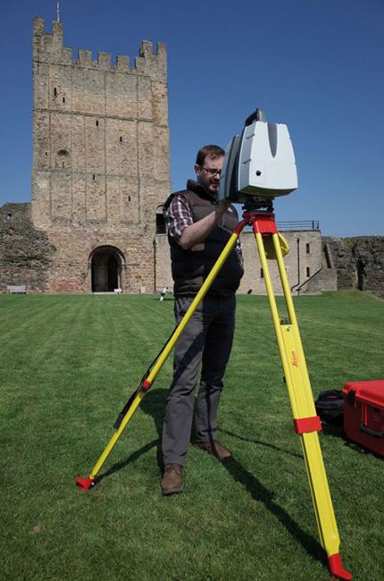 The case clearly shows that the process required a minimum of time and effort.
Using FARO 3D Scanners on Justin Timberlake's World Tour
Source: disguise.one
Timberlake's "Man of the Woods" program features scenery brought to life on stage. First, the ScanLAB team digitized a number of corners of the forest in the US state of Oregon. Laser projectors then directed images over the auditorium and stage, painting amazing images of the Portland landscape on translucent canvases suspended in the air.
Source: faro.com
Two Faro Focus X 330 laser scanners, Faro Scene 6.2 software were used to prepare visual effects. In total it took 40 digital copies and 1 working day in the concert hall.
Source: www.esa.int
Considering the limited preparation time, the large surface areas for displaying the image and the corresponding need for high image resolution, creating visual effects in a short time without using the chosen technology was impossible.
Selection guide for 3D laser scanners
In the review, we introduced you to the equipment of market leaders with an excellent reputation. All devices described have high performance, so we recommend to pay attention to these devices for use in various fields:
FARO Focus: Focus3D S350, Focus 3D S150.
Creaform: MetraSCAN 350 (350 Elite), MetraSCAN 750 (750 Elite), HandySCAN Black (Black Elite).
SHINING 3D: FreeScan X5 (X5+), FreeScan X7 (X7+).
ScanTech: KSCAN20, PRINCE 775, PRINCE 335.
Results
Source: 3d-scantech.com
These examples clearly prove that the use of 3D laser scanning optimizes workflows in many areas. The range of tasks solved with the help of 3D laser scanners is constantly expanding.
Buy a professional 3D laser scanner at Top 3D Shop — experienced specialists will help you choose the most suitable equipment, software for your business, and offer a project to modernize production.