Whistle 3d print
Whistle best 3D printing models・Cults
COMPATIBLE CONCH SHELL CARNIVAL WHISTLE
€30
Loud Whistle
€0.94
Whistle with variable lanyard loop
Free
Gift Box for "Call-Your-Beloved-Whistle"
Free
Gift and Storage Box for Keychain Whistle Set
Free
Train Whistle Toy
Free
Loudest Whistle for Your Keychain
Free
Whistle
€1.15 -20% €0.92
Exclusive Infinity Pencil Extension: Whistle by vavrena.
€0.80
Call-Your-Beloved-Whistle (Valentine's day gift)
Free
Whistle (very loud)
€0.50
CARNIVAL PITO
€2
The magic whistle
Free
Little Bird
€0.87
Hi-performance whistle
Free
Duo Tweety
Free
Basketball whistle
€0.50
5 Feature Emergency Whistle
€2.08
Shrill Little Whistle / Zipper Pull
Free
whistle whistle
€1.55
MINION REFEREE WITH GRU MY FAVORITE VILLAIN CARD AND WHISTLE
€2
Pen Bird Whistle
Free
whistle
Free
Triple Thrill Emergency Whistle
Free
Death whistle
Free
KEYCHAIN SAFETY WHISTLE
Free
Customizable whistle
€1
whistle toy
Free
Simple one-tone flute
Free
BUBUZELA CORNETA SILVATO
€1. 87
Owl Whistle - the whistle that sounds like a real owl!
€2.50
Whistle
€0.50
Ankh V29 Whistle
Free
Carnival whistle
€1.50
Sonic animal repeller for car
€1.99
3D Printed Pocket Siren Whistler
Free
Steam whistle, signal horn single 1:45, gauge 0, O gauge
Free
whistle
€1
Wiener Whistle
Free
Whistle head
Free
Emergency & Sports Whistle
€0.50
Chirping bird whistle
€1. 79
Tesla Cyberwhistle
€1.87
Aztec Death Whistle
€1.31
Maya / Aztec Death Whistle sliced
Free
Cyberwhistle Tesla whistle
Free
Dog whistle
€1.25
Death Whistle 4 Pack
€5.61
3d Printed Whistle - Etsy.de
Etsy is no longer supporting older versions of your web browser in order to ensure that user data remains secure. Please update to the latest version.
Take full advantage of our site features by enabling JavaScript.
Find something memorable, join a community doing good.
( 89 relevant results, with Ads Sellers looking to grow their business and reach more interested buyers can use Etsy’s advertising platform to promote their items. You’ll see ad results based on factors like relevancy, and the amount sellers pay per click. Learn more. )
Best 3D Printable Whistle・Cults
COMPATIBLE CARNIVAL WHISTLE FROM KONCHAK SHELL
30 €
Loud whistle
0. 94 €
Adjustable lanyard whistle
Free
Whistle Gift Box "Call Your Darling"
Free
Gift box for storing a set of whistles-trinkets
Free of charge
Train whistle toy
Free
Loudest keychain whistle
Free
Whistle
€1.15 -20% 0.92 €
Exclusive Infinity Pencil Extension: Whistle from vavrena.eu
0,80 €
Whistle to call a loved one (Valentine's Day gift)
Free
Whistle (very loud)
0. 50 €
CARNIVAL KENNEL
2 €
Magic Whistle
Free
Little bird
0.87 €
High performance whistle
Free
Duo Tweety
Free
Basketball whistle
0.50 €
5 Emergency whistle feature
2.08 €
Squawk / Zipper
Free
whistle whistle whistle
1.55 €
MINION JUDGE WITH "MY FAVORITE VILLAIN" CARD AND WHISTLE
2 €
Feather Whistle
Free
whistle
Free
Triple Thrill Emergency Whistle
Free
Death whistle
Free
SECURITY WHISTLE FOB
Free
Adjustable whistle
1 €
whistle toy
Free
Plain plain flute
Free
BUBUZELA CORNET SILVATO
1,87 €
Owl whistle - whistle that sounds like a real owl!
€2. 50
Whistle
0.50 €
Whistle Ankh V29
Free
Carnival whistle
1,50 €
Sound animal repeller for car
1.99 €
Whistler 3D Printed Pocket Siren
Free
Steam Whistle, Single Horn 1:45, Gauge 0, O Gauge
Free
whistle
1 €
Viennese whistle
Free
Whistle Head
Free
Emergency and sports whistle
0.50 €
Chirping bird whistle
1. 79 €
Cyber whistle Tesla
1.87 €
Aztec death whistle
1.31 €
Mayan / Aztec death whistle with thread
Free
Cyber whistle Tesla whistle
Free
Dog whistle
1.25 €
Death whistle 4 pcs.
5.61 €
Prototyping workshop - 3D printing, milling, scanning, electronics development
Rounded corners issue during printing
It is clear that due to the round shape of the nozzle of a 3D printer, when printing parts, it is impossible to make their corners perfectly sharp. In addition, when printing square corners, depending on the speed, additional plastic build-up may occur due to the print head slowing down when passing the corner of the part. For example, when the head slows down, the pressure of the nozzle increases, as a result of which a layer of plastic is squeezed out a little thicker than if a normal straight surface was being printed.
This effect is noticeable in the photo below - although the corner of the part was perfectly square in CAD, the printer could not print such a corner. Even worse in the photo looks a slight influx of plastic from above.
It seems that in most cases a rounded and slightly enlarged corner will not be a problem, but what if you are trying to print a square part that should fit into a square hole, such as a lid?
If you want to avoid this problem, then it is enough to make the corners a little rounded in advance, at the model development stage.
Printing of finished assemblies
Models are built layer by layer on a 3D printer. Perhaps this fact can be used for some trick. So, for example, in some cases, a 3D printer can print a product consisting of different parts, immediately assembled, and not print each part separately, in order to then assemble the product itself from them.
When developing models of this type, it is necessary to make sure that the various parts of this model cannot stick to each other, as well as move relative to each other. This situation can happen when you have one part printed directly on top of another part, and this can be a big problem when printing because the filament extruded directly in the air will bend unpredictably, which will lead to sagging of the top of the product, due to which it can stick to the bottom. To avoid this type of problem, it is very important to leave a sufficient gap between the parts of the printed product, and the width of this gap for each case will be individual.
For example, if the part overhang is very small, say 10mm in diameter, then you can set the gap height to 0.5mm. Well, if the overhanging part is long, or has a complex geometric shape, then, accordingly, its sagging will be much greater and, therefore, it is necessary to proportionally increase the height of the gap. The easiest way to figure out how much clearance to set is to try and see how the problematic part of the model will print. By creating small test models, you can spend much less plastic time than if you printed the entire product every time you try to eliminate errors.
The illustrations below show an example of a composite product printed as a single piece. This is a folding dust filter.
Top image - complete filter model
The lower image is a section of the hinge (loop) of the filter
As you can see, the hinge (hinge) has a protrusion of about 45 degrees, which allows the 3D printer to easily print the part, as well as avoid the sagging problem that would lead to sticking of the hinge (hinge) parts.
When you work in 2D space, with the X-Y coordinate plane, you can create parts of models with fairly tight tolerances. So, for our part, the minimum gap is only 0.2 mm. But there is another problem that you may encounter - this is the so-called stretching of plastic threads between adjacent parts, which again can lead to gluing parts of the product.
You can get more information about this problem and how to fix it here.
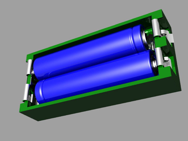
Of course, you can print not only connected parts of one product. So, as one very common example, you can bring a whistle that has a ball inside, and this ball is printed from the very beginning along with the whistle itself. At the end of the press, the ball is pulled out of the whistle, but in such a way that it remains inside, due to this it can sound freely.
The cost of printing does not depend on the complexity of the form
By this heading we mean that the printer doesn't care whether it prints a cube or an intricate set of shapes. There is no doubt that printing a simple cube does not require a large number of nozzle movements, so the print time will be lower compared to complex models. But if you omit this fact, printing complex forms is definitely beneficial, because the cost of printing does not actually depend on the complexity of the form.
A classic example of this idea is commercial aircraft parts such as the bracket in the picture below. We can optimize its shape by not cutting it out of a solid piece of metal, but printing it out of plastic on a 3D printer.
Image taken from Airbus.com
We believe that with traditional manufacturing tools, we will never be able to create perfect voids in a model, unless we can make something similar to such voids with drilling/milling. But, when using 3D printing, we have the possibility of placing a cavity under a thin layer of plastic, which will further increase the strength of the model and reduce the mass of parts and consumables.
Joining large parts
Even with 3D printers such as Ultimaker and Ultimaker2, which have fairly large printable areas, there may be a situation where you need to print a part larger than the printer's printable area. To get out of the situation - we will divide the model into several parts, print the parts separately, and then connect them together. The easiest way to connect is to glue the parts together. Obviously, this way we will achieve the desired result, but do not forget that we are using a 3D printer, so why not get creative?
But let's go back to gluing for a second. For convenience and smooth gluing of parts, as well as to facilitate this process, you can add holes and round pegs to them on the corresponding sides of the models. As a rule, this is enough to be sure that the parts are connected correctly and, while the glue dries, not only places will not move, but also relative to each other.
If you need to glue a rather narrow part to a wide one, then in this case you can print special guides that will fix the glued part in relation to other parts of the part. Make a couple of mounting holes in the parts to be joined, then fasten the guides, leaving a small gap so that when gluing the parts, the location of the parts remains correct.
If you don't like the method of gluing parts, you can peep several ways from joiners. For example, the dovetail joint is used by woodworkers and there is no reason not to use it in 3D printing.
This complexity of design does not complicate the manufacture of parts, you can also leave the connection temporary or fix the parts together with glue.
Assemble to print all parts in one go
It is always tempting to print a large part at once, but as often happens, fixing its first layer on the platform and then printing the whole part evenly is quite problematic. Therefore, do not be afraid to print several details at once. Here are a couple of reasons why it's best to print some parts piecemeal: first, you can get rid of supports, which, let's face it, take a very long time to remove; secondly, thanks to this method, the strength of the part can be significantly increased.
Let's look at the first reason. Surely you have encountered the difficulty of printing protruding elements of parts. Of course, the best option when printing overhangs is to eliminate them at the stage of product modeling. But, if this is not possible, then you can divide the model into several parts and arrange them in such a way that the protrusions are no longer a problem.
The figure shows an example of a part that is difficult to print at one time, regardless of its printing position. For printing, you will have to use a large number of supports, which will lead to high material consumption. But, if you break the model into two parts, then printing will be much simpler, and instead of removing the supports, it will be enough for you to connect them with glue. Pay attention to the added chamfers at the hole and the peg - this is done to simplify the connection of parts of the part.
Strength is another reason for splitting a part into several parts. If you need to print a narrow cylinder perpendicular to the substrate, then it makes sense to print it separately, lying on the table, this will give it strength, since the printing direction will be along the longitudinal axis of the cylinder.
How to make the fixing of perpendicular parts of the part stronger
Suppose you want to print a vertical cylinder on a cuboid. At the junction of the figures there will be too sharp a transition, due to which the part may break if you press on the cylinder. You can strengthen the part by adding a ring of the appropriate height to the model at the junction of the figures (see the figure below).
Addition of metal elements to increase the strength of plastic parts
Currently, the vast majority of 3D printers print with various types of plastic, but compared to plastic, metal has much more durable characteristics. Why not try to combine the best of these technologies? We can use the print pause function to add iron parts to parts and then resume printing. A great example is to insert metal nuts into the right places of one part, then to screw it with screws to another part.
Make sure you have enough material around the nut, otherwise the nut will play when you tighten the screw. Strengthening the area around the nut can either be done by printing a few extra lines around the perimeter or by tricking the slicer into 100% infill where needed.
How to print horizontal holes
When printing horizontal holes, the top edge overhangs and creates an arc. This means that the horizontal holes will be slightly flattened at the top and will shrink in size. There are several ways in which you can align the holes.
The first approach is to reshape the hole during the modeling phase, making the hole look more like a water drop. This makes the printing process easier as there is a slight gap for the plastic to sag during printing.
You may not like the look of the resulting hole. In this case, there is another way that you can use. It consists in creating a thin support membrane that supports the edge of the hole in one of the places.
If you don't care about the look of the hole and are going to use it for practical purposes, you can also experiment with different hole shapes. How about a triangle or square with one of the corners pointing up? Basically this idea is useful for small holes. Remember to leave clearance around the hole if a screw will be inserted into it.
Increased strength due to 100% filling
3D printer uses different software. And some programs do not allow you to set multiple plastic fill options during printing. In such a case, to increase the strength of the part, you can increase the amount of plastic fed or the number of perimeter walks for the entire part.
But you can use a trick to get around this shortcoming and create a model that prints more plastic in areas where you need it. The method consists in adding a group of cylinders in the place where more strength is needed. This will force the program to print many cylinder print lines, which will fill the area more densely.
The illustration below shows an example of this trick. It shows a product in the form of a box with a little excessive filling. In this case, cylinders with a diameter of 0.5 mm were used at a distance of 1 mm from each other. For each specific situation, you will have to experiment with the dimensions of the cylinders and the distances between them in order to find the optimal values. Cylinders must necessarily cross the upper and lower planes, otherwise unpleasant situations may arise during printing. Play with the settings (for example, in Cura's "Fix horrible" slicer) so that the slicer doesn't throw cylinders out of its calculation. In any case, in the program, before printing, it is necessary to check the appearance of the layers.
Below is another example where we added many small holes around one large mounting hole. It turned out not one hundred percent filling, but, nevertheless, unlike the hole of the same size on the right, it is much stronger.
Round corners to reduce distortion
Curvature occurs more frequently at sharp corners, which are areas of increased stress and material stress during printing. By rounding the corners, you will slightly reduce this effect.
Strength-oriented optimization
To get an idea of how durable your printed parts are, try imagining they are made from wood. If you've ever chopped wood, then imagine that it's much easier to cut along the fibers than across.
Think about your printed parts in this way. Position and design them to be as solid as possible. If you have a complex part with sticking out parts, then you can break it into several parts, and then assemble it after printing. By doing this, you can not only save time, but also get rid of supports.
Consider plastic shrinkage after cooling
We have already noted that parts after printing tend to decrease in volume when cooled. This is especially problematic for small holes. To avoid this, you need to scale the holes to compensate for shrinkage. Over time, you will gain experience, and you will automatically understand how much to scale an element to compensate for compression.
It is worth noting that if your model has few polygons, then this will also lead to a decrease in holes. Since the hole is a series of straight lines, the low number of polygons means that the lines will run over the diameter of the hole. As a rule, this situation will not lead to a strong decrease in size, but it is still worth remembering.
For a better understanding of the problem of downsizing, you can print a model with different hole diameters, and compare what size is in the computer model, and what turned out after printing. This will help you better scale the holes while modeling.
Model closure, what is it and why is it important?
A model that is not "closed" cannot exist in the real world. This means that the model has edges or vertices floating in space, areas of zero thickness. This also applies to "permeable" models, which, for example, have holes in the form of a grid.
It is important to correct these errors as they can confuse your slicer and lead to unpredictable print paths. There is a free online service for fixing such problems, you can find it here.
It may also be worth trying to change the export settings in your CAD system to avoid errors. A setting such as the resolution of the exported model may solve the problem.
Wall thickness
If your model contains thin walls, it might be a good idea to make them multiples of your nozzle width (0.4mm for UltiMaker2). If you make the wall thinner than the nozzle width, it's possible that your program will remove it entirely from the model if it realizes it can't properly print such a thin wall.
45 degree rule
When designing the model, you should try to keep the angles of the protrusions to a maximum of 45 degrees. The printer is capable of printing angles greater than this angle, but if you are aiming for good surface quality, then reduce the angle as much as you can. The steeper the angle, the worse the print quality.
The illustration shows how models could be designed for the best possible 3D printing experience. The first image shows that the top of the model has an obvious overhang that must be maintained if the goal is to print correctly. Of course, it is possible to print the part using supports, a little more about this will be written below.
The image in the middle shows a 45 degree overhang angle change for easy printing. But, of course, this is not always possible. Alternatively, this part should be used as a belt roller, which should be in the middle and have stops.
In the third version, we split the model into two parts, and added a pin and a hole so that the parts can be glued together after printing. This approach keeps the edges straight.
Create your own supports instead of automatically generated ones
Whenever you have a part of a model hanging in the air, you need print supports. They allow you to print parts that are usually impossible to print just like that. The bad thing is that after removal, they leave scratches on the surface.
Lifts can be generated automatically or you can make them yourself. Most printing software makes supports automatically and they do the job, but these supports are difficult to remove and leave scratches on the surface. An alternative would be to use a separate program, such as Meshmixer (link). While the built-in generators create a "block" of support structures under the overhanging part of the model, Meshmixer instead tries to use small columns of material for support. An excellent guide to using this program can be found here.
But the best way is to create supports manually when developing the model. Humans are still smarter than computers in this area and can be a little more resourceful about how best to build support. So you can save printing time and plastic. You can also prevent and hide any scratches. The picture below shows the overhang and two supports in red.
This image shows automatically generated supports. Note that the default settings have been applied. But you can tweak some settings to improve the result a bit. In our example, ironically, the automatically generated support itself requires support.
In the image above, the homemade support (highlighted in red) nicely supports the protrusion and we can take advantage of the 3-D printer's properties to apply material at small intervals. The printer will start printing on the perimeters that are fully supported by the custom supports. These perimeter lines will form the base for the plastic that will be applied to the rest of the gaps.
When creating the support, it is important that you leave a small air gap between the support and the actual model so that the support does not blend into the rest. What the gap should be depends on the height of the layer and how the model looks. As a rule, a gap of 0.15 mm is used.
Create lintels instead of a steep canopy if possible
As mentioned above, supports leave scratches on the surface. They also waste a lot of time and plastic. Therefore, you should try not to use them.
The printer cannot print what is in the air, but it can print small bridges in the air. We call this effect the "bridge" effect, as it essentially stretches a strand of plastic between two bases, similar to the cables on suspension bridges. On this page there are a large number of different models printed on different types of printers that use jumpers.
Taking advantage of the "bridges" effect is very useful when printing, for example, models, such as a model of a house with open windows. A short span over an open window can be easily bridged, saving both time and plastic.
This does not mean that the bridge effect is miraculous, of course it has its own problems. For example, you can't bridge long gaps with bridges and still expect the bottom surface to look perfect, as sagging plastic threads are inevitable in this case. Short spans, however, may not be a problem. To reduce slack, it's best to slow down the print speed and make sure the extruded filament cooler is working so well that it becomes stiff as quickly as possible.
This image shows a typical case where a "bridge" might be a much better choice if the design allows it. A gently sloping overhang is likely to have very poor surface quality on the underside. By making a straight bridge, you can improve the print quality. If you want a flat overhang, you can of course use a support to print it, but again, the surface will be rough.
The illustrations below are printed models illustrating the quality of the surfaces.
Slopes and stepped slopes
Since the printer creates an object by superimposing one layer on another with some offset, a "ladder" will be visible after printing, and not a smooth curve. If you are a gamer, then this aliasing effect is most likely familiar to you, it looks similar.
You won't notice this effect on a vertical surface as the layers will be on top of each other. As the angle increases, the effect will become more and more pronounced. You can soften it by lowering the layer height. The illustration below shows this.
As you can see, thinner layers can render the true shape much better. Also notice how much worse the top of the object looks compared to the bottom layers. As the angle increases, the rings become more visible.
Currently, some printing software (including cura) does not allow you to select (or automatically detect) areas that need thinner layers to reproduce the detail in the best possible way. So if you find that you need extra resolution then print the entire object with a lower layer height. Of course, this will increase the print time a lot.
We suggest you use the Slic3r program. This slicer will allow you to select different layer heights for different print areas to get the best quality and print speed.
But, of course, there are other alternatives, such as trying to design your models in such a way that their slopes are not very smooth and streamlined.
Plastic shrinkage
Unfortunately, this is only a small part of all the problems that you will encounter if you are trying to create parts with very precise dimensions. The degree of shrinkage depends on many different parameters, such as: type of plastic, shape of the part, cooling, heating / no heating of the base, etc.
In short, there are many nuances. This problem is not unique to FDM printers, it also affects injection molding, for example. The molding also needs to compensate for how the plastic will shrink in angles and dimensions.
So how do we deal with this? We are experimenting. Consider an example - usually vertical holes are smaller than expected. The problem is exacerbated if these holes are small. So if you want the hole to fit an M3 screw when printed, you have to make the hole in the CAD bigger than it needs to be. If you want the screw to sit quietly, you can try, for example, a diameter of about 3.4 mm. You can print part of the part, measure the result, and then modify the CAD model with the desired hole dimensions. This is not an exact algorithm of actions, but with experience you will automatically determine how to compensate for shrinkage in order to achieve a good result.
Perhaps you were surprised that vertical holes are especially troublesome to print? The answer is simple - when you print a hole, the plastic sags down into the void below it (obviously), since the plastic behaves almost like rubber (when heated), which shrinks.
In addition to shrinkage, as you can see, the first layer is usually printed flattened, resulting in an even smaller hole. The use of a chamfer will help to cope with this problem.
Use chamfer to print a quality bottom edge
The first layer is usually pressed against the platform more strongly than subsequent layers. This is to ensure that the first layer adheres better to the platform, and as a result, the lower surface is smooth, like a mirror. The downside is that the dimensions of the first layer are larger (or smaller depending on how you look at it). You can negate this effect by adding a fillet to the bottom of your model. Depending on the height of the first layer and the height of the layer for the rest of the print, rounding can be from 0. 4mm to 1mm. The gap will give the plastic some room to expand.
It is important that you can use a chamfer instead of a fillet. Rounding will create a serious overhang that will look ugly. The chamfer, as a rule, is done at 45 degrees, the printer will be able to print it very beautifully.
If you still want a fillet on the bottom of the part, you can make a chamfer and make a fillet on the top. By doing so, the overhang will fail. The picture above shows the difference. Note that the red highlight is the overhang, which will be difficult to print compared to the slight 45 degree angle from the chamfer + fillet.
A trick for a beautiful top
In addition to the information listed here, there is a very neat trick that was first introduced by Dreamworker on the Ultimaker forums. This trick is useful for parts with a flat top that has holes in it.
Dreamworker suggested covering the lid with plastic, covering the holes.