Tinkercad to 3d printer
Practical 3D prints: A first TinkerCAD project for your 3D printer
This is the beginning of a series on practical prints for your 3D printer. Lots of people have seen 3D printers in action, but many of the prints are what can best be called novelty prints. They're action figures or statues of gaming miniatures. Practical prints like brackets and basic signs are shown far less often (probably because they're not as photogenic).
But I find 3D printing enormously helpful in solving practical problems. Whether it's adding support to an organizational system to free up desperately needed space, a way to make sure our mail carrier picks up the mail, or a system for remembering what was last fed to the dog when both of us care for him, 3D printing has come to the rescue.
Most of the time, especially for quick-fix projects, I use a free 3D modeling tool called TinkerCAD. It's incredibly simple and easy to use. I also use Fusion 360 for more complex models and SketchUp for woodworking projects. In cases of hybrid projects, I'll sometimes use more than one tool.
In this article and its accompanying video, we're going to use TinkerCAD. Let's get started.
The problem we're solving
The problem statement for this project is very simple. My wife and I wanted our mail carrier to pick up our mail when we put something outgoing in the mailbox. Unfortunately, that wasn't happening. So, when I called my local post office, they said we needed a flag on our mailbox for the mail carrier to pick up our mail.
The solution was 3D printing. Today, I'll show you how to make a very simple magnetic flag for your mailbox. You can apply this to all sorts of things, but in our case, I made it for the mailbox cover.
Editing in TinkerCAD
The project consists of a couple of basic objects. As the video shows, we're going to start by bringing out a box. I'm able to pull on a corner and make it bigger. I'm going to change its height and as you can see in the video, there are handles.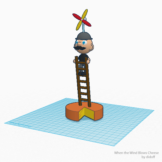 There are corner handles, there are center handles. By pulling and pushing on the handles, we're able to create a long rectangle that will form the backbone of the flag.
The entire design consists, then, of one long rectangle. That rectangle is duplicated and shortened. That makes the flag. Then a square is created that's the size of the flag, rotated 45 degrees, and used to cut out the triangle portion of the flag. I know it's a bit confusing, but the video shows it all very clearly.
Earlier, I created a shape that's basically a short cylinder. I named it "workshop magnet" because it's exactly the size of one magnet in a set of 100 magnets I bought a few years ago.
The idea of the predefined shape is that anywhere I put it, TinkerCAD will hollow out a space for the magnet to fit. Once space is hollowed out of the long rectangle for two magnets, we're done. We have a 3D model that we can turn into a practical print.
Sending it to the printer
That's the entire 3D design for this project.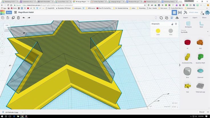 All we need to do is select it, export it as an STL file, and send it into Cura to be sliced for printing. Then I sent it to the Ultimaker to print.
And that's it.
So there you go, a very simple mail flag for our mailbox. As you can see, it's just a simple set of TinkerCAD primitives connected and printed out. The result: Our mail is being picked up.
Be sure to explore TinkerCAD. It's simplistic but it's surprisingly powerful at the same time. Stay tuned for more practical prints.
And what about you? Have you made useful things with your 3D printer? If so, let us know in the comments below.
You can follow my day-to-day project updates on social media. Be sure to follow me on Twitter at @DavidGewirtz, on Facebook at Facebook.com/DavidGewirtz, on Instagram at Instagram.com/DavidGewirtz, and on YouTube at YouTube.com/DavidGewirtzTV.
3D Printing
How To: Basic 3D Design using Tinkercad
May 02, 2018 How To
by Braydon Moreno
The most overbearing part of 3D printing going mainstream is 3D design — most users think the process of designing and creating a model is extremely difficult, but I am here to show you that it is actually quite simple.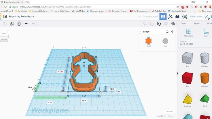
If you’re looking to get into 3D design, TinkerCAD is a great place to start. TinkerCAD is a free, online design tool for beginners. The application is designed to educate users – providing both tutorials and a series of interactive lessons on how to use this tool. Its ease of use makes it a great option for anyone wanting to try their hand at 3D design.
After creating an account on TinkerCAD, you will be prompted to go through a short tutorial. This tutorial will introduce the use of geometric shapes to create objects. It covers the basic tools for positioning shapes, combining and subtracting shapes to create new ones, and using the Workplane tool to aid in alignment.
After completing the TinkerCAD tutorial, you’re ready to start making!
Video 1 (featured below) shows the TinkerCAD dashboard. You can start a new design by clicking on the blue ‘Create new design’ button. Your past designs will also be shown in the dashboard with the option to edit them.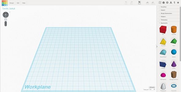 Once you start modifying a design, TinkerCAD will save your changes as you go along. If you want to make a backup of a design before editing, click on the gear icon of the design and select 'Duplicate'. This will create a copy of the design you can work with.
When you start a new project, TinkerCAD automatically generates a name for you. You can rename the project from within the editor by clicking on the Design menu.
Once you’re comfortable with some of the basic functionalities of the dashboard and the workpanel, we will go ahead and get started on designing your first simplistic print - a keychain. You can add your name to the keychain, your nickname, your dorm room, your favorite sports team, or anything that you like. Check out the how to video below.
Now that you have designed a keychain, you can understand that the functionality of TinkerCAD is very simple.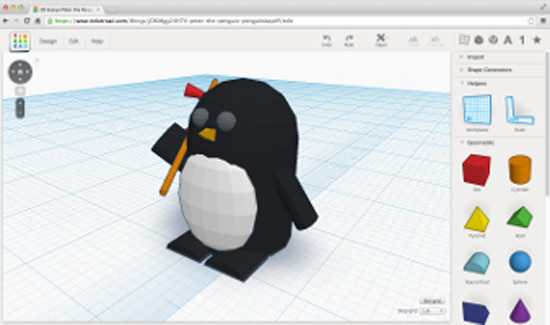 You can go in and start experimenting, but I also want to show you one more video of a slightly more complicated object that will help you with a few more tools in the TinkerCAD toolbox. The video below will show you the design process and also how to export as .STL file, which you will use that file type to take directly to your Robo 3D Printer.
Once you’re satisfied with your design, printing your TinkerCAD designs on your Robo 3D Printer is a simple process. All you need to do is download your design as .STL file, you can drag and drop it into your CURA software or save it onto a thumb drive, plug USB into the printer, and go through the steps for onboard slicing. It's that simple!
Why .STL?: .STL is a standard file format for three-dimensional models that has been around for a long time and is widely supported by almost all design programs.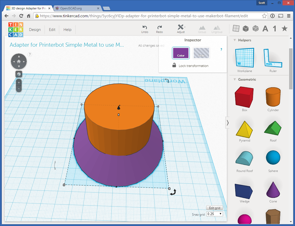 When a design is saved in this format, the design program translates the design into a surface map, and saves it in either a binary or text format.
With TinkerCAD the process from an idea to a finished print is streamlined. The principles you learn through using the tool will remain relevant, even as you move on to more advanced design programs. The tutorial is only a brief overview of some of the features that the platform has to offer. For more in-depth training, you can access interactive lessons under ‘Collections’ in the left-hand side of your dashboard. You can also find the tutorial video and other training resources here.
Be sure to show us what you designed in Tinkercad and 3D printed on your Robo 3D Printer! Share it on social media using #robo3d or below in the comments.
Make a cup in this tutorial. Cheers!
Make the Parthenon quick and easily!
Make this Eiffel Tower all on your own!
Related Posts
Post Processing with Painting
by Robo 3D | September 07, 2018
3D Printing For Your Next Camping Adventure
by Braydon Moreno | July 11, 2018
Memorial Day 3D Printed Commemoration
by Robo 3D | May 28, 2018
Guide to the basics of 3D modeling.
 Getting to know Autodesk Tinkercad / 3D printers, machines and accessories / iXBT Live
 I have been fond of 3D printing for a long time and at first it was interesting to download finished models from Tingivers or Maminifactory, these were mainly decorative items or widely used parts. But what if you need a replacement for the leg of your favorite chair, an unusual stand for a gamepad / flashlight / phone, or a case for some kind of homemade product? That's right, learn to model. Of course, you can immediately start with the powerful and free home application Fusion 360, but it is not so easy to learn and most of those who want it are quickly eliminated, so I suggest starting with its younger brother tinkercad 'a
To get started, no software installation is required, all manipulations are performed in the browser. We follow the link, click "join", then "create a personal account", in the last step I used the login using my google account, which noticeably speeded up the process »
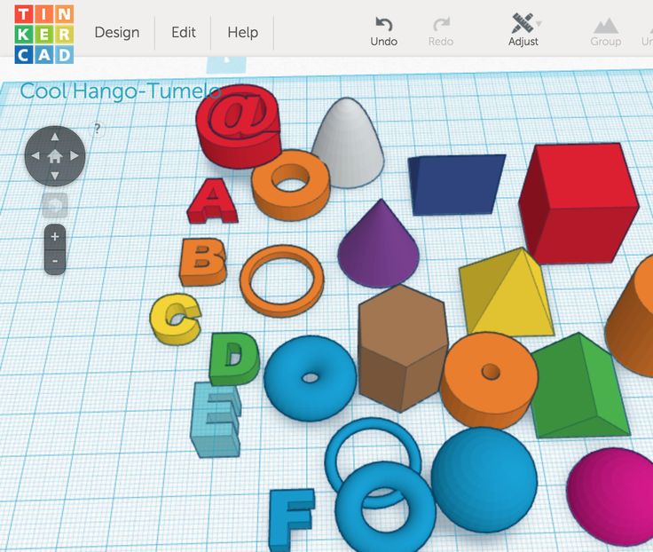
A window will load with a work plane, a minimum number of tools at the top and shapes on the right
By dragging the desired element on the plane, you can change its size and position relative to the surface, some objects have additional parameters in their properties, such as the number of segments, smoothing, etc. , the shape change occurs in real time during correction, so that it turns out quite clearly
It will not work to draw a complex shape here, so you have to use a system of bodies and holes, as well as a small set of tools in the upper right corner:
- Copy (Ctrl+C) - copy one or more objects, hotkeys are supported Copy and repeat (Ctrl+D) — creating a duplicate of the selected objects in the current project window
- Delete (Del) — deleting the selected objects
- Left arrow something went wrong
- Right arrow (Ctrl+Y) — moves to the latest changes
- Group — combines models into one, while “sintering” intersecting surfaces and as a result we get a monolithic part that can be further edited
- Ungroup - again divides the model into components so that you can edit a separate part without affecting others
- Align is both a simple and very useful tool that allows you to shift models relative to each other along three axes with alignment to the edges or center.
 Need to make a small square hole exactly in the center of a freeform model? No problem, a couple of clicks and the details are in the right places, after which you can move them manually if necessary
 - Mirror reflection - everything is logical here, select the model, the desired plane and get a mirror image. It is convenient when plans for the placement of elements change during design and you don’t want to redraw everything from scratch. You can also quickly create cases consisting of two halves with symmetrical fasteners and grooves for fixing the filling, just create a duplicate of the model and flip it in the right direction
- Selecting the object type subtraction at the intersections of models. A kind of analogue of the operations "boss" and "cut" in older brothers
Well, now I'll try to fix all this in practice. For example, I need a through hole exactly in the middle of the cube. I simply create a cylinder of the desired diameter and height, select both objects, use the " Align " tool to center them on the x and y axes, then select the cylinder and redefine it as a hole
So that our objects "sinter" and holes become holes, just select them and press the "Group" button
In the same way, you can remove the extra part of the part, and not just gnaw out pieces. For example, I need a small cylinder on one side to connect with other parts. You can create two cylinders of different diameters, define the inner one as a hole, pull them up to the top of the cube and merge the three shapes. And you can duplicate our cube, increase it in size to obtain the required outer diameter, define it as hole
Align to the center of the main model, lift to the desired height and merge the two objects. Literally a dozen clicks
You also need a small cutout in the upper part. We throw a cube, spit it, center it, raise it, group it
The main thing here is to have at least a little developed spatial thinking in order to understand how to make a complex shape out of several simple ones. At first I did not succeed well, but over time I began to imagine what needs to be done even before I started the service. Moreover, this skill later came in handy in more complex programs.
There is also text in the basic shapes, so you can model various tags, key rings, signs, etc. very easily. In addition, the service allows you to import your own models for editing, so you can sign them for memory.
Stretch the cube to 100*100mm and flatten to 5mm, this will be the base. Next, you need to click on the "Text" object and drag it with the mouse to the right place
There are not very many parameters here, there is Cyrillic support. Well, then on the knurled. Align, define as a body or hole and merge, thereby obtaining either a raised inscription or a stencil
You can also raise the text layer a little if you want to sink it a little.
Started on a square platform, but in the process decided that an oval body would look better? Not a poll, we put on a “pipe”, select the size, convert it into a hole and combine it with the main model - done
any other program
The import of models for quick correction is also supported, for example, to correct the scale, make a couple of holes or cut off a piece of wall that interferes with the transformer
thinking, and more complex programs will be easier to master. Of course, the tinkercad looks rather poor, in the set of tools there is only the most necessary - we can say that this is such a paint among CAD systems, but it will be more difficult for a beginner to get confused in it, and simple projects can be done much faster than in full-fledged modeling programs. For example, I put the dial for a frameless watch in a laptop in a couple of minutes, during which time I could only turn on the computer and launch Fusion
And not so long ago, a library of electronic components was added, so it became even easier to design housings for homemade products, because. it is clearly seen in what places the elements will rest against the walls, where it is necessary to place the fixing elements, to arrange everything more densely.
There is also a section of the shape generator, with which you can quickly design gears, threads and much more, although this will draw on another full-fledged article, and I don’t even know if anyone will be interested in such material at all, but I hope that at least someone helped to take the first steps in mastering something new)
start with 6 easy steps
3DPrintStory Reviews Tinkercad 2021 Tutorial: Get Started with 6 Easy Steps
Tinkercad is probably one of the easiest and most intuitive 3D modeling tools out there. It runs in a web browser and is free, making it the perfect software for beginners.
To learn the basics of Tinkercad, we will design a simple wrench. It should be a familiar tool with a modest shape, which can then be easily printed on a 3D printer.
We divided the entire process into six simple steps:
- Project
- Design of the Ring
- Designing handle
- Designing a dumb key
- We collect all together
- Adding text
at the end of this small tutorian you can design a wrench yourself, but also learn how to create any simple 3D model in Tinkercad.
Step 1: Set up a project
All you need to get started with Tinkercad on the web app is to create a free account on their website.
At the end of this process, you are greeted by the Tinkercad tutorial screen. Skip it for now by closing it, and instead go to the home page and click "Create New Project".
Main interface
This is the main interface of the project. As you might expect, the very center is the "Workplane" on which models are created. The interface also consists of the following elements:
- Top toolbar with more general tools like Copy, Paste and Delete on the left, and operations like Group and Align on the right.
- Basic orientation navigation tools such as zoom in and out. Note that these special tools can also be used with the mouse wheel.
- Panel containing all the building blocks for design, including basic shapes such as cubes, spheres, and text.
Divide and Conquer
Now that we're familiar with the Tinkercad interface, let's get straight to the design.
"Divide and Conquer" is a key principle in 3D modeling. Basically, it tells us to break the part into smaller shapes and shape them individually. These parts will then be put together to create the final object.
This method is especially useful when modeling complex objects from the real world. For our model of a wrench, we will divide it into three main elements: a ring, a handle, and a sponge.
These blocks will be designed in the next three steps and after that they will be connected together. In the sixth and final step, we'll add text to the wrench so we can quickly determine its size.
Step 2: Designing the ring
The wrench ring can be thought of as a solid disc with a hollow circular area in the middle, sort of like a very thick washer.
To create this shape, first drag a cylinder from the Basic Shapes panel onto the work plane. When you click on a shape, its parameters are displayed in the Shape section. We won't go into them now, but it can be interesting and useful to explore features like Chamfer.
When selected, you will notice that the cylinder has five white squares or "handles", four of which are in the bottom plane of the figure and one is above the cylinder.
Dimensional adjustment
The four knobs on the lower plane can be used to adjust the length and width of the cylinder. We want our ring to be 25mm in diameter. After you click on the white square marker, a small rectangle will be displayed with the current dimensions.
Either drag the square handles until the cylinder is 25mm long and wide, or enter values by clicking the size field and pressing Enter (Tinkercad will by default bind any drag to whatever value is displayed in the bottom right corner, e.g. "1mm ").
The handle above the cylinder adjusts its height. We want our wrench to be 4mm high, so tweak it the same way you did with the length and width.
Boolean operations and holes
We are making progress. The solid disk is ready, now we just need a hole in the middle.
Tinkercad works on the principle of Boolean design, which allows you to subtract objects to create empty areas and add objects to form new shapes (note that these terms are not used explicitly).
In this step we will use the subtraction operation to create a round hole in our ring. First drag another cylinder to the workbench and adjust its length and width to 12. 5mm, which is the diameter of the hole we want.
Now the most interesting part. With this new cylinder selected, click Hole in the top right window. This will make Tinkercad treat this shape as something to be subtracted.
Alignment
Now we need to place a cylinder-shaped hole in the middle of the hard drive. To do this, use the alignment tool on the top toolbar.
First, we need to select the objects we want to align. Left-click on the hard drive and, while pressing Shift, left-click on the cylinder hole. If you do everything right, both objects should be selected and selected at the same time.
Click the Align button on the top toolbar. You will notice that black round handles will appear on the work plane. Click on the bottom middle handle as shown below to align the objects to their center axes in the X and Y directions.
Grouping
When the two shapes are aligned, click the Group button on the top toolbar. You will see that only one form remains.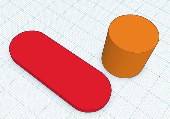 This tool essentially connects two shapes together, and if one of them is a hole, it removes the material. If everything went well, you should have your ring ready.
We have learned quite a lot in this section. For example, we now know how to size basic shapes, create holes, align objects, and finally how to group (or merge) shapes together. These skills are 90% of everything required to design 3D objects in Tinkercad.
You will see that the next steps will involve using the same or similar approaches. So go ahead!
Step 3: Designing the Handle
The handle is probably the lightest part of our wrench. We just need a rectangle of the right size.
Start by dragging a rectangle from the Basic Shapes panel onto the work plane. Set the box length to 100mm and width to 10mm using either of the two procedures previously described. Then set the height to 4mm to match the ring.
That's it! The pen is ready to go.
Step 4: Design Wrench Opening
We're almost done - only one left! Looking at the mouth of the key, you can see that its design is very similar to the design of the ring. At least at first...
The throat is also a round disk, but this time with a hexagonal hole cut at an angle. Set the disc diameter to 30mm and height to 4mm.
Polygons and hexagons
In order to create the required shape, we will use the basic "Polygon" shape. By dragging the polygon onto the workplane, you will see that it is hexagonal by default. This is exactly what we need, but it is worth remembering that we can change the number of sides of the polygon by adjusting the corresponding parameter in the form window.
For now, all we have to do is turn our hexagon into a hole.
Alignment
Now place the hexagon. Let's use the alignment tool again to position the hex along one of the disk's central axes. (In other words, center it in one direction, not two directions.) Select both shapes, click the Align button, and click on the black round marker as shown below.
Both shapes still need to be separated, so we need to place the hexagon inside the disk. To keep the alignment you just made, hold down Shift and drag the hexagon so that it is partially inside the disk. The hexagon should move in a straight line.
Size and grouping
Now that both shapes are correctly positioned, we can set the dimensions of the hexagon. We will create a 15mm wrench, but you can experiment with it and choose any size you need.
It's time to do the magic of subtraction! Select the hexagon and disk and click the "Group" button in the top menu. That's all. Congratulations!
Step 5: Putting It All Together
So far, we've designed all the individual parts of the wrench. Great job! It's time to finally put it all together.
Let's start with the handle and ring. Align both shapes in the same way as we did in the last step, that is, only in the direction of its length. Then, while holding Shift, move the ring in a straight line towards the handle. Be sure to overlap the two shapes a bit (look at the image below), and when that's done, group them. This should merge the handle and ring into one. Notice that the model now has one color instead of two different ones.
And now let's attach the pharynx to our not quite finished key. In our case, the pharynx is facing the wrong way. We need to fix it by rotating it.
Rotation
First, select the shed by clicking on the previously created object with the left mouse button. In addition to the white handles, note the three curved handles with double arrows. When you move the mouse pointer over a point in the lower (XY) plane, the angle value will appear.
To rotate the shed, click and drag the handle around the shape, or enter a value manually. Here we need a 45 degree clockwise rotation (tip: holding Shift will limit the rotation you can snap to).
All that is left to do at this stage is to connect the mouth of the key and the base to the handle. The procedure is more or less the same as we did for connecting the ring and the handle.
First align both shapes and then drag the shed while holding Shift in the direction of the wrench. Once again, arrange them so that they overlap each other a little. Finally, group them.
Color change
At this point you should have a full wrench. Cool? Let's change its color one more time.
To do this, select the finished wrench and click the "Body" button in the form window. A wide selection of colors will be displayed. I suggest dark grey. Looks better, right? This doesn't really affect your final 3D model per se, but color-coded multi-element designs can make designing more organized and therefore easier.
And here it is! The perfect wrench is ready!
Step 6: Add Text
So now that our wrench looks just right, you can consider 3D printing it. Indeed, with the skills you have acquired so far, you will be able to design and print a whole set of wrenches!
But can you tell each size just by looking at the key? Most likely no. So, in this last step, we are going to add size information directly to the handle.
To do this, find "Text" in the Basic Shapes panel and drag it to the work plane. Text works like any other shape, but we can change its content. Since we want to "cut" the text out of the pen, make a hole in it.
Adjustment and positioning
Let's change the text content. In the form window, click on the "Text" field and change it to "15mm", which is the size of our wrench. The form will change automatically.
Now all that's left is to resize the text and match it with the wrench. Set its length and width to 32mm and 7mm respectively.
To place the text above the pen, let's use the alignment tool again. Select both shapes and click Align. Since we want the text to "bite" into the top of the wrench, we'll select the top round handle vertically, as shown below.
This will make the top surfaces of both shapes flush. Finish placing the text by clicking the middle round handles in the XY plane. All that's left is to cut out the text by merging the shapes and you should be done!
Export your 3D model
You are now ready to 3D print your first Tinkercad part.


