Sweep 3d scanner
Scanse Sweep 3D Scanner Kit - KIT-14482
Retired KIT-14482
Note: Retired Product
This product has been retired from our catalog and is no longer for sale. This page is made available for those looking for datasheets and the simply curious.
Favorited Favorite 6
Wish List
Retired KIT-14482
Note: Retired Product
This product has been retired from our catalog and is no longer for sale. This page is made available for those looking for datasheets and the simply curious.
- Description
- Includes
- Documents
The Scanse Sweep 3D Scanner Kit is an advanced 60-piece DIY kit that gives you everything you need to assemble a 3D scanner using your Scanse Sweep LIDAR sensor (not included). Outdoor 3D scanning has been around for decades, but has traditionally been much too expensive for home use. This kit aims to put this powerful technology into the hands of makers who want to develop and experiment with applications for long-range 3D scanning. The only tools you will need are a soldering iron, wire stripper, small Phillips-head screwdriver and 2.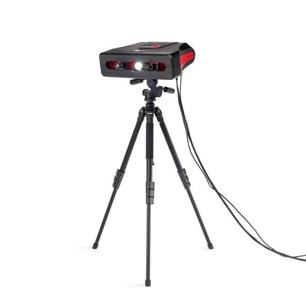 5mm ball-end hex key.
Each Scanse Sweep 3D Scanner Kit is controlled by an included Raspberry Pi 3, a stepper motor and driver HAT, and a 9DoF IMU --- all housed inside an included 3D-printed enclosure. As the Scanse Sweep rotates in its seat, the top of the 3D scanner pivots back and forth, providing a complete three-dimensional scan of its surroundings!
This kit is not a finished product, but an evolving community effort. It’s built for DIY enthusiasts who want to get their hands dirty and try new things. We aren't kidding; there is a lot of work that goes into assembling this kit, so we only recommend it for those of you looking for a challenge. If anything happens with any of the parts while you are assembling the kit, there is a full list of parts included in the kit, as well as 3D print files in the Documents tab.
Note: This kit does NOT include a Scanse Sweep, which will need to be purchased separately.
Important: As this is a DIY project, we are not offering any guarantee, dedicated support or refunds.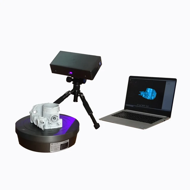 Any support questions should be directed to the forum community and the issues tracker on the project GitHub page (found in the Documents tab). Buyer beware! We will not accept any returns on this product!
- 1x Raspberry Pi 3B
- 1x Adafruit DC and Stepper Motor HAT for Raspberry Pi
- 1x Adafruit 9-Axis IMU --- BNO055
- 1x MicroSD Card Reader
- 1x 14mm Circular Bubble Spirit Level
- 1x 16GB MicroSD Card
- 1x MicroUSB Female Cable
- 1x Sinoele Ultra Slim 10000mAh Power Bank
- 1x Super Glue
- 1x Double-Sided Tape Square
- 2x MicroUSB to USB 3.5in Cable
- 1x SS-01GL13P --- Snap Action Switch, SIM Roller Lever
- 2x 3/16in Heat Shrink Tubing, 0.5in Long
- 1x 2.54 Pitch Single-Row 90 Degree Pin Strip Cut to 3pin, 3pin, 4pin
- 1x 10K Inline Resistor
- 7x Jumper Wire, 8in (2 Blue, 1 Yellow, 1 Green, 1 Black, 2 Red)
- 11x Phillips-Head Machine Screw 0.092-28, 0.375 LG
- 4x Phillips-Head Machine Screw 0.
 092-28, 0.75 LG
 - 4x Flat-Head Machine Screw, M2.5, 4mm LG
- 2x Flat-Head Machine Screw, M3, 6mm LG
- 3x Socket-Head Cap Screw, M3, 8mm LG
- 1x 1/4-20 Nut
- 2x Nylon Unthreaded Spacer --- 94639A711
- 1x 14HR08-0654S --- 0.9DEG 4.55V Round Stepper Motor
- 3x Ball Bearing --- 3mm x 8mm x 3mm
- 1x Spherical Scanner Cover, Square (P0087)
- 1x Spherical Scanner Battery Holder, Square (P0088)
- 1x Spherical Scanner Cable Clip (P0090)
- 1x Spherical Scanner Light Pipe (P0091)
- 1x 90 Degree Cylindrical Scanner Bracket, Tall (P0092)
- Assembly Instructions
- Webapp User Guide
- 3D Print Files
- Software GitHub
- Scanse Sweep Forums
Scanse Sweep 3D Scanner Kit Product Help and Resources
- Videos
- Skills Needed
Video title
Core Skill:
SolderingThis skill defines how difficult the soldering is on a particular product.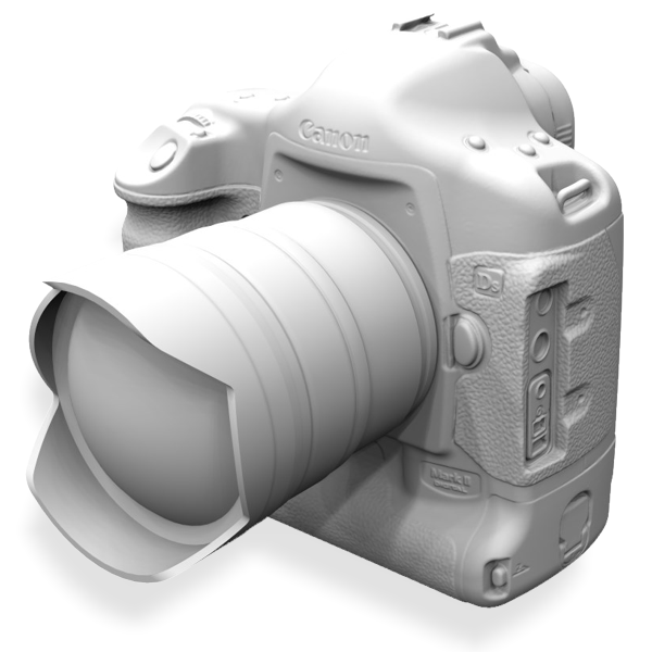 It might be a couple simple solder joints, or require special reflow tools.
3 Soldering
Skill Level: Competent - You will encounter surface mount components and basic SMD soldering techniques are required.
See all skill levels
Core Skill:
RoboticsThis skill concerns mechanical and robotics knowledge. You may need to know how mechanical parts interact, how motors work, or how to use motor drivers and controllers.
3 Robotics
Skill Level: Competent - You may need an understanding of servo motors and how to drive them. Additionally, you may need some fundamental understanding of motor controllers.
See all skill levels
Core Skill:
DIYWhether it's for assembling a kit, hacking an enclosure, or creating your own parts; the DIY skill is all about knowing how to use tools and the techniques associated with them.
5 DIY
Skill Level: Expert - At this point, you should have a solid understanding of power tools and have access to a shop full of equipment. You might need to make a custom mold, have access to a CNC machine, or design custom parts.
See all skill levels
Core Skill:
ProgrammingIf a board needs code or communicates somehow, you're going to need to know how to program or interface with it. The programming skill is all about communication and code.
3 Programming
Skill Level: Competent - The toolchain for programming is a bit more complex and will examples may not be explicitly provided for you. You will be required to have a fundamental knowledge of programming and be required to provide your own code. You may need to modify existing libraries or code to work with your specific hardware. Sensor and hardware interfaces will be SPI or I2C.
See all skill levels
Core Skill:
Electrical PrototypingIf it requires power, you need to know how much, what all the pins do, and how to hook it up. You may need to reference datasheets, schematics, and know the ins and outs of electronics.
3 Electrical Prototyping
Skill Level: Competent - You will be required to reference a datasheet or schematic to know how to use a component. Your knowledge of a datasheet will only require basic features like power requirements, pinouts, or communications type. Also, you may need a power supply that?s greater than 12V or more than 1A worth of current.
See all skill levels
- Comments 5
- Reviews 0
No reviews yet.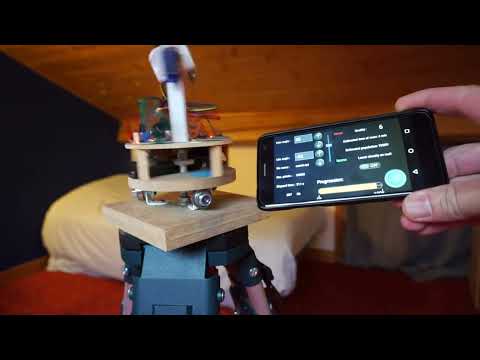
The Theory Operation of 2D Scanner LiDAR Sensor (Sweep 3D Lidar )
The Sweep device is a two-dimensional scanning LiDAR sensor, comprised of a single one-dimensional range finder which spins 360 degrees. This means that as the device rotates counterclockwise, it effectively records data in a single two-dimensional plane. The name “Sweep” comes from this sweeping motion (rotating while accumulating/gathering data).
The device rotates continuously. The idea of a single 360-degree scan is simply a delineation of all of the data gathered during a single 360-degree rotation.
Read our Other Printers Reviews: 1. Best Sublimation Printer - 2. Best 11x17 Color Laser Printer - 3. Portable 4X6 Photo Printers -
The Sweep is NOT a three-dimensional scanner, nor does it have a vertical field of view other than the expansion of the single beam. Using the Sweep for 3D scanning requires some form of mechanical manipulation to transform the 2D scan plane produced by the Sweep.
See the Sweep Manual for technical details.
3D Lidar Scanner Sample ImageAdaptive Sampling
Internally, the Sweep uses a one-dimensional rangefinder, referred to as the “sensor module”. Understanding how the sensor module operates will help you understand the data produced by the Sweep. Here is a brief excerpt the Sweep Manual:
[wps_quote style=”style-3″ cite=”Cameron Moll” url=”https://scanse.io”]
The light packets that Sweep uses can vary in length, which can affect accuracy of range measurements, as well as the maximum range and update rate. Under normal operation, Sweep limits the maximum time per measurement to a value determined by the sample rate set using the LR command (see LR packet structure description).
If not enough light is returned from the environment, the measurement fails, and a 1 is returned as the range value. On the other hand, if a lot of light is returned from the environment, the correlation algorithm can reach its maximum accuracy early, and can return a range value more quickly. This is what makes the update rate of Sweep variable.
The value of setting a slower sample rate using the LR command, is that more light will be gathered from a target, and the range measurements will be more accurate. The exact accuracy is determined by many factors, including the target surface characteristics and ambient noise, so we cannot give an exact number for relative accuracy between the different LR settings.
[/wps_quote]
To produce a single ranging/measurement sample, the sensor module performs many quick measurements (sub-samples), and aggregates them together to produce a final range measurement (sample). You can think of the final sample as a sort of average of many sub-samples. The final sample is provided with some confidence value based on the quantity & quality of sub-samples.
If the set of sub-samples is not of quantity or quality to produce a valid final sample, the sensor module will continue sub-sampling until it collects some maximum threshold number of sub-samples. If the sensor module is still not confident in the set of sub-samples, the Sweep will return a reading with a range of 1cm indicating a failed reading.
This kind of adaptive sampling yields more performant data, but at the cost of consistent structure. There are noteworthy differences between the data produced by Sweep and the data produced by other 2D rangefinders.
Readings do NOT Occur at Fixed Angular Intervals
Sweep sensor readings are variable. That is to say, azimuth values (the angle at which the reading is recorded) do not come in fixed intervals. Instead, the azimuth values are dictated by when the sensor module produces final range samples. For this reason, every sensor reading includes an azimuth value.
As a stationary Sweep device comes about the same angular range on subsequent rotations, the readings will occur at unique angles. Eventually, the Sweep will produce a denser angular resolution over time as it continues to spin. This is different than other devices which produce measurements at fixed angle intervals.
Variable Sample Rate
The nature of adaptive sampling means that the Sweep does not have a fixed sample rate. The Sweep will produce variable sample counts each time it rotates 360 degrees. That is to say, if you group sensor readings together into complete 360-degree scans, then the number of samples in two subsequent scans might be slightly different.
The effective sample rate can change (increase or decrease) depending on the environment. Say for example, that the sensor was mounted at a 90-degree angle, such that half of the angular range pointed directly at the sky. When the beam is pointed at the sky, the range is infinite and the sensor module’s sub-samples never succeed. As the beam rotates across the sky (shown as a red dotted arrow), the sensor module will continue sub-sampling, waiting for confident measurements.
Whenever it has attempted the maximum (threshold) number of sub-samples, it will return a final reading with a range of 1cm indicating an invalid reading. These invalid readings are not drawn in the illustration below. After the device outputs an invalid reading, the sensor module will immediately proceed with sub-sampling for the next reading. The angular region where the beam is directed into the sky would result in an angular region of many readings with 1cm range. This angular region is marked by the red dotted arrow in the illustration below.
Therefore, the sample rate effectively halves. This is an extreme example of course, but it is meant to illustrate the variable nature of the sample rate.
A similar case could occur if the material properties in the environment prevent light from returning to the sensor module. This occurs with very dark (black) objects, translucent objects such as windows, or highly reflective objects such as mirrors. These kinds of material properties can manifest as gaps in the data, where the sensor module was not able to acquire valid readings as the beam passed over the object. In these regions the Sweep will produce readings with a range of 1cm, to indicate an invalid reading.
Sample Rate Settings
The previous section described how the sample rate is variable, however, the Sweep does provide three sample rate settings (500Hz, 750Hz, 1000Hz). These settings can be thought of as a target range for the expected number of samples in a roughly “normal” environment.
The sample rate settings (500Hz, 750Hz, 1000Hz) are defined by changing the threshold or the maximum number of sub-samples the sensor module is allowed to use to produce a final reading. Faster sample rate settings limit the sensor module to fewer sub-samples per reading. In the illustrations below, the 500Hz sample rate setting allows the sensor module to gather twice as many sub-samples (dotted red lines) before producing a single reading (green dot), as compared to the 1000Hz setting.
Sample Rate SettingsTherefore, a slower sample rate setting will produce more accurate measurements, because more sub-samples can be used to obtain each reading. Conversely, the accuracy of the readings will drop for higher sample rate settings. For certain applications, such as a robot in an indoor environment, a faster sample rate might be more important than range or accuracy. Be aware of this trade-off when designing your applications.
Expected Data Density
The previous sections outlined how the sensor module uses a form of adaptive sampling which can lead to variable sample rates. Be aware that the density of data is greatly affected by the makeup of the environment (geometry, distance, material). However, the following tables can still be useful as a ballpark estimate for data collection.
The approximate number of samples (readings) per revolution based on the motor speed and sample rate setting:
Lidar Sensor of 2D Scanner Expected Data DensityTearing/Ghosting
Because the Sweep is continuously rotating, the nature of the sensor module’s adaptive sampling can yield a tearing or ghosting effect at the edge of an object.![]() More technically this can occur anywhere where there is discontinuous or disjoint environmental geometry. This is an edge case to be aware of, but it is easy to spot.
More technically this can occur anywhere where there is discontinuous or disjoint environmental geometry. This is an edge case to be aware of, but it is easy to spot.
Consider the following scenario. Two pieces of geometry sit at different depths, but both provide very confident and strong range responses. While the beam is over the first object, all of the sensor module’s sub-samples (shown as red dotted lines) are measuring parts of the same continuous geometry. The sub-samples yield very similar distance measurements, and therefore produce a confident and accurate final sample (the green dot).
Tearing/GhostingHowever, on the next sample, the beam passes over the disjoint edge of the first piece of geometry. The sensor module’s sub-samples (shown as red dotted lines) are spread out across the two pieces of geometry. Despite the different distance measurements, all sub-samples yield strong responses, so the final sample (green dot) is inaccurately averaged between the two.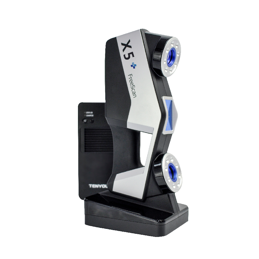 This manifests as a reading where no actual geometry exists, hence the name ghosting or tearing.
Note: Higher sample rate settings can reduce this effect, as the angular window for the calculation of each reading is narrowed.
Table Of Contents
- 1 2D Scanner Lidar Sensor Operation Theory
- 2 Adaptive Sampling
- 3 Readings do NOT Occur at Fixed Angular Intervals
- 4 Variable Sample Rate
- 5 Sample Rate Settings
- 6 Expected Data Density
- 7 Tearing/Ghosting
App Store: Qlone 3D Scanner
Description
** Featured by Apple for Object Capture **
Turn photos from your iPhone or iPad into high‑quality 3D models that are optimized for AR using the new Object Capture API on macOS Monterey.
Object Capture uses photogrammetry to turn a series of pictures taken on your iPhone or iPad into USDZ files that can be viewed in AR Quick Look, seamlessly integrated into your Xcode project, or used in professional 3D content workflows.
Scan with Qlone on your iPhone and Process on your Mac! Our familiarly beautiful AR dome will guide you through the scanning process.
alternative, you can also process a set of your own images in a Folder or ZIP file.
Version 1.0.2
Minor fixes and optimizations.
Ratings and reviews
The scanner is good, AR is not very good.
In general, the scanner works well, if everything is done according to the instructions, you can get an excellent result, the only thing that is not clear is AR: for some reason it is completely impossible to expand the object. If you scanned it in a lying position, then in AR it will always lie on the ground and cannot be turned over in any way.
It's frustrating.
Just awful.
Sorry for the money. Deceivers. This program does not allow you to get high-quality models. Tried all options. Turntable tripod lighting. The quality is terrible ... no words.
Hello paasigpilrstgasil,
We are sorry for your troubles and we are here to help!
To see the quality that you can achieve with Qlone, just take a look at our gallery on Sketchfab:
https://sketchfab.com/Qlone/modelsAs with any new technology, there is a learning curve to get to good quality results but here are a few important tips for getting there:
https://www.youtube.com/watch?v=WAvWqTzmylM&list=PLFyWT8cl6wJdcQEUYTAEXW-TFjytt6lRFPlease let us know if these helped and feel free to reach out with any question to our support team at:
qlone@eyecue-tech.com
Thank you,
The Qlone team
Scan Quality
The quality of scanning on the mat leaves much to be desired, and the resulting model is very different from the demonstrations.
Developments
Developer EyeCue Vision Tech has indicated that, in accordance with the app's privacy policy, data may be processed as described below. Detailed information is available in the developer's privacy policy.
Unrelated with user data
The following data may be collected, which is not related to the user's identity:
- Geoposition
- Usage data
Sensitive data may be used differently depending on your age, features involved, or other factors. Read more
Information
- Provider
- EyeCue Vision Technologies LTD
- Size
- 140.7 MB
- Category
- Graphics and design
- Age
- 4+
- Copyright
- © 2022 EyeCue Vision Technologies LTD
- Price
- Free
- Developer site
- Application support
- Privacy Policy
Other apps from this developer
You may like
3D scanning of parts to order in St.
 Petersburg. Departure in St. Petersburg
 Services
3D scanning is used to obtain an accurate digital model. When working, there is no mechanical contact, so the procedure is suitable for any surface (from the smallest parts to large objects, the size of a car). It is very easy to increase the image accuracy, it is enough to increase the number of analyzed points.
The image result can be easily converted to different formats and then processed on a computer.
The finished mathematical model can be used for printing on a 3D printer. To print the finished 3D model, special materials are used, depending on the desired results. A 3D model of an object printed using a printer is not just an image on a piece of paper. This is a full-fledged three-dimensional model that can be used in various fields of activity.
3D scanning applications
This technology is used in various fields: medicine, industry, architecture, etc. Digitization services are in high demand in many areas of life:
- Production of souvenirs.
- Medical business (surgery, cardiology, etc.).
- Creation of computer games.
- Development of various programs.
- Instrumentation.
- Aviation.
3D scanning process
The 3D scanning procedure looks very simple from the outside. A special fixture highlights the object, and then its 3D model is displayed on the monitor screen.
However, things are not so simple. Before starting work, it is necessary to prepare the part: clean it from dirt and dust, matte it, apply dot marks. The program used by the scanner stitches the scans into a single model. The result of the work is obtaining a model in STL or OBJ format (the surface of an object, which consists of many triangles). After that, the STL model is processed and the scanning procedure is completed.
In the future, it is possible to convert the received point cloud to a solid state format, such as STEP.
Equipment used
3D scanner is a necessary equipment, without which the scanning process is not possible. The Shining3D EinScan-Pro scanner is one of the best scanning tools, which is why our company chose it to work with.
This scanner can scan objects of various sizes.
Our main advantages
- Acceptable prices for all types of services.
- Highly qualified specialists in the working staff with relevant education and extensive work experience.
- Use of professional, high-precision equipment (scanners, printers).
- Completion of work within the time specified by the customer.
- The strictest observance of technology, careful preparation of the object before the procedure.
Where can I order a 3D scanning service?
In our studio you can order services for the digitization of an object and its subsequent printing on a printer. Our specialists scan and print objects of any complexity.
Scanning and printing services is one of the main activities of our company.