Solidworks 3d printer driver
How Do I 3D Print from SOLIDWORKS?
TriMech Video Tech Tips, 3D CAD, SOLIDWORKS, Tech Tips
By David Cano-Mejia on
As 3D printing becomes more common in the workplace, users are turning to SOLIDWORKS to better understand their designs in the context of 3D printing. SOLIDWORKS offers several 3D printing visualization and analysis tools and all of them can be accessed through the Print3D tool (File > Print3D). Let’s take a look!
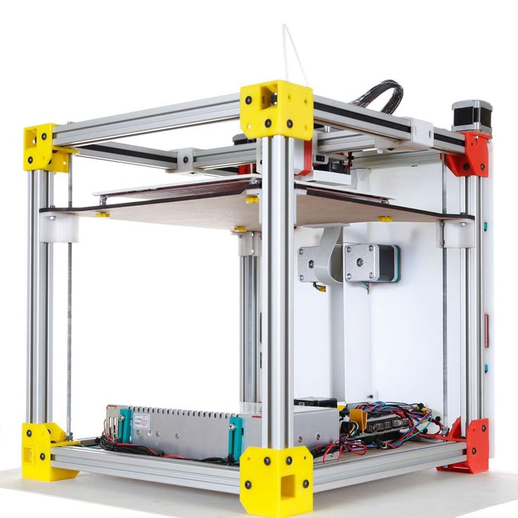
Does My Part Fit on My Printer?The first step in analyzing your design for 3D printing is to ensure that it will fit inside the print area. Under Printer, you can select the 3D printer that you will be using. If this is your first time using the Print3D command, you will need to add your printers to your favorites list. Click on Manage Favorites to browse all available 3D printers. SOLIDWORKS has added a comprehensive list of 3D printers with up-to-date envelope information so you can quickly find your most used printers and add them to your Favorites for easy access. If for some reason your 3D printer is not listed under this library, you can define a Custom Printer by manually inputting the print volume dimensions.
Under Print Bed Location select a plane, or planar face, to be defined as the bottom plane of the model. This will automatically orient your model on the print bed. If the model is larger than the print volume, the geometry outside the print volume will be highlighted in red and you will not be able to print. If you need to change the orientation of the model, you can use the translation controls, manually type in the desired print bed angle and offsets in the Print3D PropertyManager, or click Orient to Fit to let SOLIDWORKS orient your part or assembly for you.
Under Scale, you can also choose to print your design at a scale other than 1, which is the current size of the model in SOLIDWORKS. To do so, type a value for the scale factor. The new value is saved as a document property in the SOLIDWORKS file so if you print the model again, the saved value is used still there. The Scale to Fit option sets the scale to the largest value that will still fit inside of the print volume.
Can I Analyze My 3d Print?Sure! You just have to switch over to the Preview tab in the Print3D PropertyManager. There are several analysis tools that you can use to get a better understanding of the design to be printed.
- Build Analysis
- This allows you to preview the faces of your model that may require supports. Depending on the printer being used, at a certain overhang angle, the print quality is greatly affected unless supports are used. Type in the maximum angle for the faces that will require support.
 I recommend changing the Support face color to red and checking Show As Transparent to make it easy to visualize all of the faces that will need support.
- This allows you to preview the faces of your model that may require supports. Depending on the printer being used, at a certain overhang angle, the print quality is greatly affected unless supports are used. Type in the maximum angle for the faces that will require support.
- Layer Height
- This option lets you visualize the height of each print layer in order to determine whether the print resolution is sufficiently fine to produce the desired print. Type in a layer height and turn on Show Striation Lines in order to get a preview.
- If you are planning on exporting your file as a .3MF (3D Manufacturing Format), you can choose to let SOLIDWORKS generate the slices for the 3D print and embed those into the .3MF file instead of slicing the model using the printer’s slicer software
- Thickness/Gap Analysis
- If you are using FDM (Fused Deposition Modeling) for your prints, this calculates the ideal wall thickness/gap based on the material that you set and the layer height.
When you are done analyzing and visualizing your design, you are ready to export the 3D print files.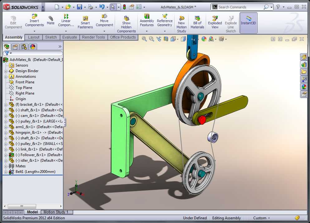 You can export part and assembly files to STL (.stl), 3D Manufacturing Format (.3mf), or Additive Manufacturing File Format (.amf) files.
- STL (*.stl)
- This ASCII or binary format file describes only the surface geometry of a 3D object as a raw, unstructured triangulated surface.
- 3D Manufacturing Format (*.3mf)
- This is a 3D focused file format that contains 3D model, material, and property information for sharing full-fidelity 3D models to other applications, platforms, services, and printers.
- Additive Manufacturing File (*.amf)
- This xml-based file lets you select export options that store the color, scale and materials of the object to be 3D printed in the .AMF file, as well as the geometry of the model.
Under Save To File, select your desired format and click Save File. Once you have one of these files, you can import it into your printer’s slicer software to generate the G-code that the printer will use to print your design.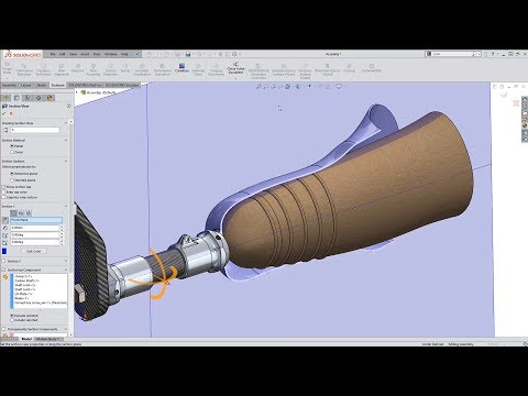
Yes, but only if your 3D printer manufacturer uses the SOLIDWORKS 3D Print API. As soon as you finish using the Print3D command and click OK , the 3D printing rapid prototyping dialog box will open to ensure that your printer’s build area is empty. The printer will start to warm up get ready to print. If your 3D printer does not use the SOLIDWORKS 3D Print API, you can still export the file as described above and import it into your printer’s slicer software.
How Do I Set My 3D Printing Options?If you are planning on printing directly from SOLIDWORKS, you can set the 3D printing options that you would typically set in the slicer software. Job Quality corresponds to the print layer height and is the printer’s approximation to match that resolution. Infill Percentage lets you select the percentage of the part that is solid. You can select between 0%, 10%, 40%, 70%, and 100%. Infill percentage can greatly affect print times and part strength. Include Raft builds the print output on top of a raft of disposable material that you can remove after printing. This option is cleared by default. Include Supports adds supports for model faces that are in open space with no part of the model supporting the face. This option is selected by default and resets to the default each time that you open the Print3D PropertyManager.
The tools available inside of the Print3D command are easy to use and set up. Even if a different slicer software ends up being used to send the model to the printer, these tools can serve as a great starting point to understand the 3D printing requirements that your specific design may have.
Ready to learn more about SOLIDWORKS? Explore the different training options that we have to offer.
Should you use SOLIDWORKS for 3D printing?
Published on May 7, 2020 by Carlota V.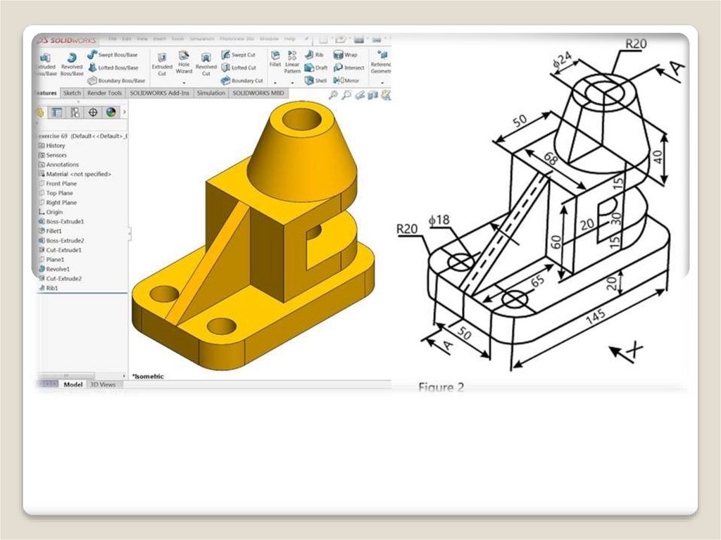
In industrial sectors and product design, SOLIDWORKS is a CAD solution many rely on. The software has been around since the mid 90s and the latest figures estimate that there are around 9.3 million active users across 80 countries. It is based on parametric modeling and is primarily used to create 3D models and assemblies. SOLIDWORKS has also been adopted in the world of additive manufacturing as it enables engineers to save their models in a STL format; the format needed for a 3D model to be processed by 3D printing software.
SOLIDWORKS was developed back in 1993 when John Hirschtick, a member of the MIT Blackjack Team, recruited a team of engineers to create the first accessible and affordable 3D modeling solution. At the time, AutoCAD, which had been released in 1989, was limited to the creation and editing of 2D geometry. Therefore, SOLIDWORKS was the first software to bring an accessible 3D modeling solution to the market. For many engineers, 3D modeling truly changed the way they could bring creations to life.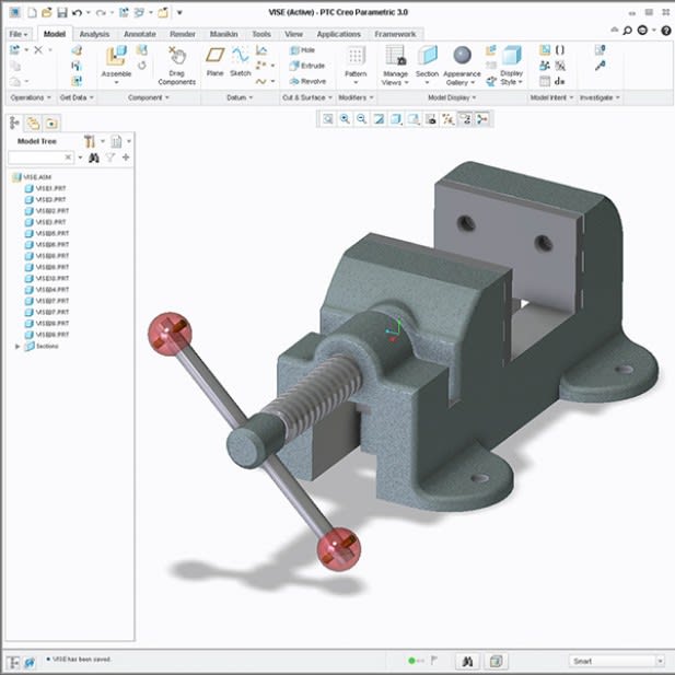
One of the first versions of the software
Soon enough the software became extremely popular and Dassault Systèmes decided to acquire it in 1997 for $320 million in stock. At the time, Dassault Systèmes was known for its CATIA solution, a product lifecycle management suite, which combines design, engineering, and manufacturing features used for automotive, aerospace and aeronautics. Essentially, SOLIDWORKS is a lighter version of CATIA.
Main Features of SOLIDWORKS
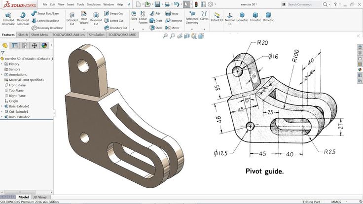
As mentioned, SOLIDWORKS is a CAD software based on parametric design. Parametric design is a process that clarifies the relationship between design intent and design response. One of the key features of parametric models is that attributes that are interlinked can automatically change their feature when one attribute is changed. This modeling process is great for projects with a lot of manufacturing requirements. 3D models can be created for high performance parts and assemblies used in sectors such as aerospace & defence or automotive.
For example, the very popular AutoCAD solution from Autodesk is primarily a 2D CAD software that caters to architects, home builders and civil engineers. Even though it is possible to create basic 3D surface and solid modeling with AutoCAD, it is not its key feature, and definitely not as easy as working on a parametric modeling software. This is the key benefit of SOLIDWORKS.
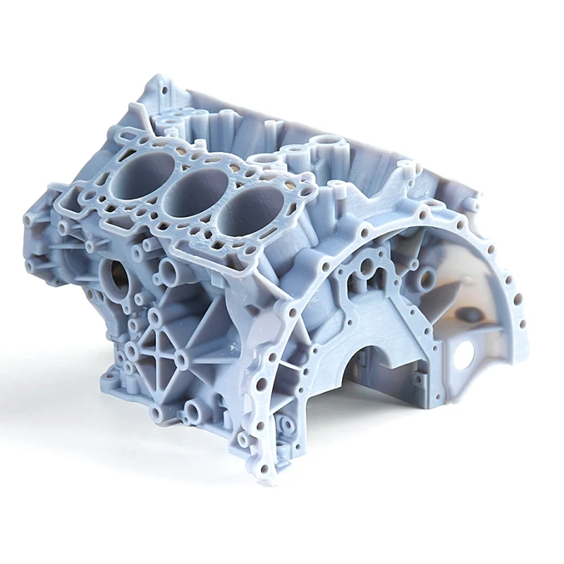
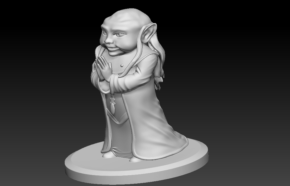
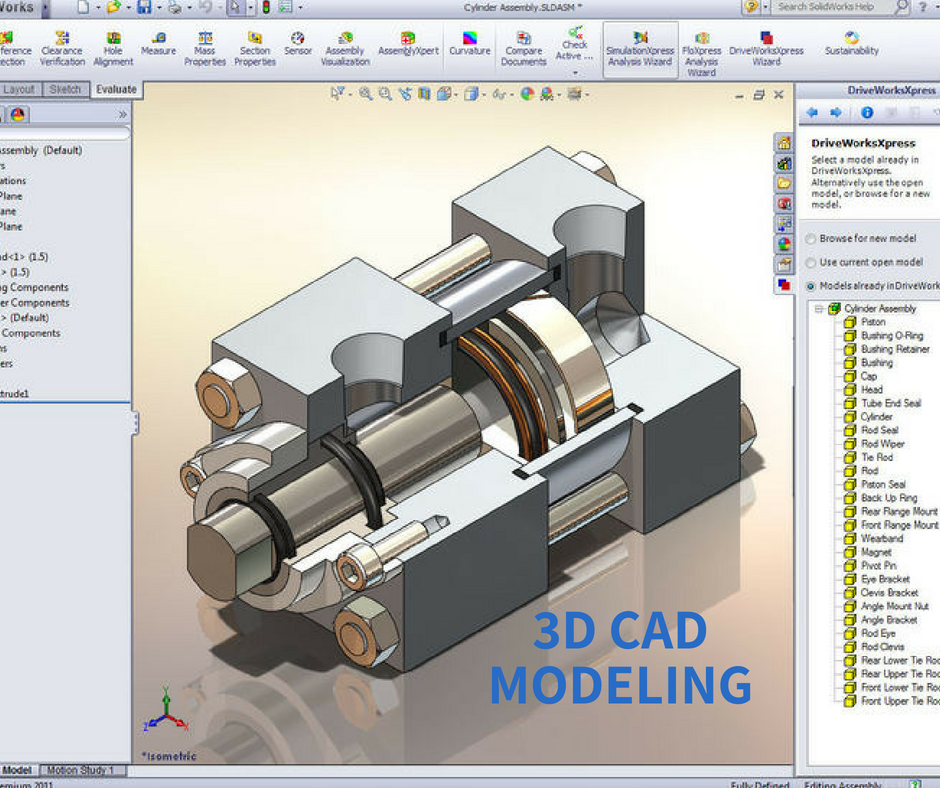
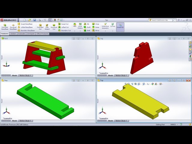
It is primarily used to model parts or assemblies (as is the case here)
Furthermore, SOLIDWORKS also includes very beneficial features for a number of industrial applications such as simulation, rendering tools and CAM (computer-aided manufacturing) tools. You will be able to create solid models with SOLIDWORKS, but also import, create, and manipulate surfaces, view models in wireframe mode, and generate 2D drawings from the 3D solid models.
SOLIDWORKS Standard
SOLIDWORKS Standard will enable engineers and designers to create parametric parts, assemblies, production level drawings, as well as generating complex surfaces, sheet metal flat patterns, and structural weldments. Thanks to its parametric design feature, the models will automatically update with design changes. Conceptual design is also an important capability of the software as it allows to create layout stretches, apply motors and forces to check mechanism performance, etc. The Standard license costs $3,995 with an annual maintenance fee of $1,295.
SOLIDWORKS Professional
SOLIDWORKS Professional builds on the capabilities of SOLIDWORKS Standard to increase design productivity, with file management tools, advanced photo-realistic rendering, automated cost-elimination, design checking and a parts library. The Professional licence costs $5,490 with an annual maintenance fee of $1,495.
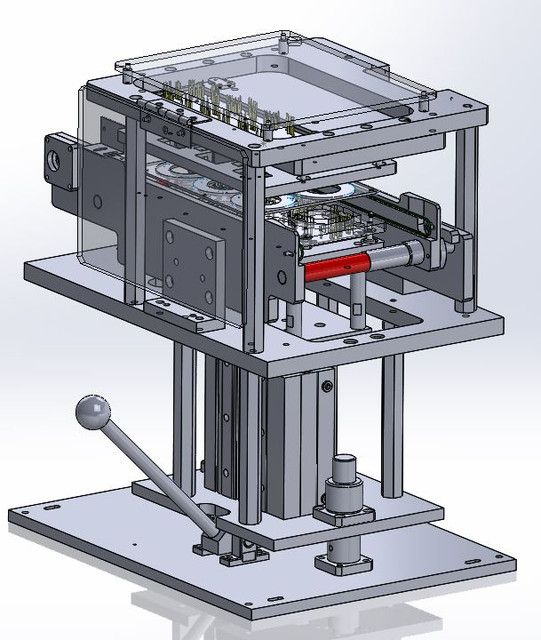
It can offer powerful simulation tools
SOLIDWORKS Premium
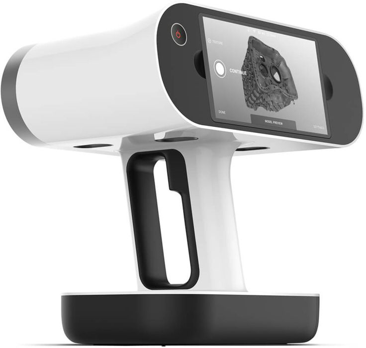
SOLIDWORKS Premium adds powerful simulation and design validation to the capabilities of SOLIDWORKS Professional, plus reverse engineering, and advanced wire and pipe routing functionality. ScanTo3D tools, available in SOLIDWORKS Premium, import mesh and point cloud data from which you can create surfaces and solid models. The Premium licence costs $7,995 with an annual maintenance fee of $1,995.
SOLIDWORKS for 3D printing
As mentioned, SOLIDWORKS can be used for additive manufacturing technologies because you can save your 3D model as an STL file. This is the format needed to transform the data from the model into G-code that a 3D printer can work with. However, this is not the only way in which SOLIDWORKS is suited for additive manufacturing projects. When designing for additive manufacturing, there will be many design considerations to take into account. Anything from distortions, warping, and breaking can occur, which means a 3D model must be adjusted accordingly.
Topology Optimization is one of the design techniques possible on SOLIDWORKS
SOLIDWORKS has put in place tools that account for the special requirements of AM techniques, including support structures, and any distortion that can arise during printing.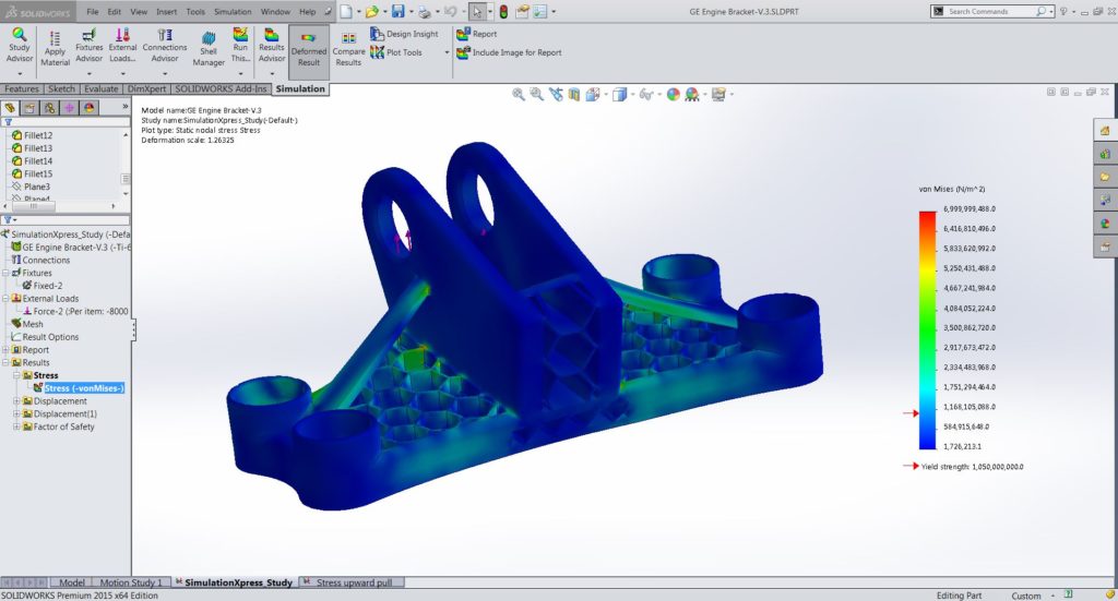 These features are extremely important, especially when working with expensive materials such as metals, where failed prints can be very costly. Finally, given the design freedom that 3D printing technologies allow, design techniques such as topology optimization can be applied to models. Another way to save material consumption and optimize a part! You can find more information HERE.
Do you use SOLIDWORKS? Let us know in a comment below or on our Facebook and Twitter pages! Sign up for our free weekly Newsletter, all the latest news in 3D printing straight to your inbox!
Software for Picaso 3D Designer
Regularly update Polygon X.
Update the printer firmware to version 5.411 (or higher) for correct operation. Designer XL PRO.
Improved work with high-poly models - increased speed of rotation and movement of models on the platform.
The "Dense Support Base" option has been added to the Professional Job Setup Mode, which allows you to choose whether the first support layer will be solid or not.
Several improvements have been made to Series 2 networking.
Several bugs have been fixed related to saving Series 2 material profiles and highlighting model surfaces on the platform.
Update 4/19/22:
This update includes workspace changes for Designer Classic, Designer X, and Designer X PRO printers running firmware version 5.516 or later, as well as new features, built-in algorithm improvements, and some bug fixes. In particular, a bug related to incorrect time output when printing jobs generated in version 2.3.0 has been fixed.
Picaso X Core engine update
- Increased speed of loading and slicing high-poly models.
- Fixed some past bugs: Adjusted the feed settings for the seam hiding paths, as well as the line widths for filling gaps between perimeters (now reduced the chance of overextrusion when using gap filling) and the first two layers of the substrate.
New Features
- Added 3D fill pattern "Lightning". This is the most economical and fastest template with automatic density that changes depending on the geometry of the model.
- Added "Mirror" function. It reflects the model about the selected axis.
Changes to current functionality
- Assembly and separation of models on surfaces is now performed through the context menu in the list of models. - The range of layer heights for auto-selection of parameters has been reduced (the "Detail" slider). For a 0.5 mm nozzle, a layer height of 0.4 mm is excluded, since this height does not guarantee good print quality on a wide range of materials at high speeds. However, you can still set these parameters manually. - Fixed model scaling error, in which the final dimension could be 0.01 mm larger than required, and some other application errors.
Interface Changes
- Minor changes have been made to the interface for viewing profiles in the PICASO 3D cloud base.
- Tips for 3D printing best practices are now displayed when preparing a job for a long time.
- A full version of the program in Spanish has appeared.
Minimum system requirements:
- OS Windows 7 (or higher)
- . NETFramework version 4.7.2 (or higher)
- Screen resolution of at least 1183x700.
Polygon X version 2.1 and above runs on the new Picaso X Core engine, which significantly expands the range of possibilities for users.
List of what you'll find inside:
- New program registration/activation system.
- Updated interface.
- Accelerated process of generating print jobs.
- 3 modes for preparing print jobs: from the "no numbers" mode to the mode with more than 100 parameters.
- Custom presets that can be downloaded and shared with other users.
- The mechanism for automatic selection of settings for any nozzle diameter (officially presented by PICASO 3D).
- 4 automatically configured types of support.
- Unique settings for individual models within a single print job.
- New modes and functions: Vase, Smoothing, Reverse Model, Protective Shield, Adaptive Layer.
- Bug fixes for previous versions.
Driver for 3D printer
For the correct operation of any 3D printer, you need a special device that will be responsible for controlling the stepper motor.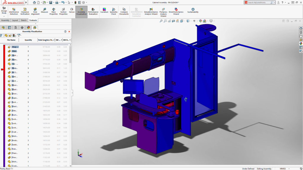 Incorrect installation or malfunction will result in printing problems or damage to the printer itself.
What is a 3D printer driver?
The 3D printer driver is a device whose main function is to control the kinetic movement of the printer's stepper motors. The driver sends commands to the microcontroller that describe the movement of the shaft - the number of steps and direction, at the output receiving a sequence of signals specified in a certain way for the motor winding. The driver in this process is responsible for converting one signal to another.
Manufacturers offer many models of 3D printing drivers that vary greatly in quality. Top models are able to maintain high output currents while maintaining an acceptable operating temperature, and are able to control the motor so that it does not make excessive noise, does not overheat, and the print head moves smoothly, without jerks and accelerations.
Drivers are used everywhere where stepper motors are used: in all CNC machines, actuators, 3D printers, laser engravers, etc.
Modern 3D printers use kinematics and a control method, which consists in the sequential transmission of the coordinates specified for the movement of the hotend. Methods is the generally accepted standard for controlling all devices equipped with a CNC unit. Data transfer is carried out in a specially developed programming language called G-code.
Control boards and drivers are responsible for the physical movement according to the given code.
Boards, in turn, are divided into two types based on their capacity:
- 8-bit.
- 32-bit.
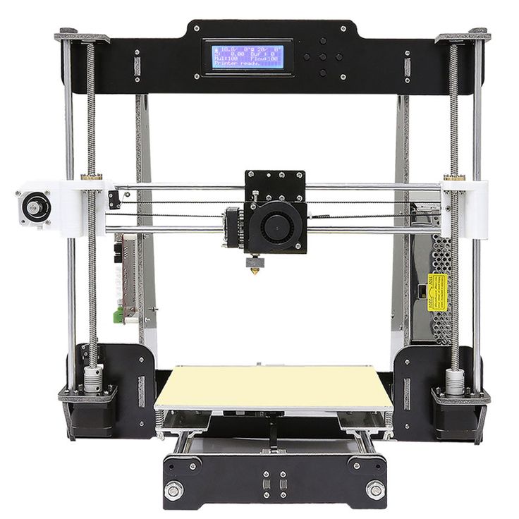
The first 3D printers were designed using the self-replicating mechanism used to rapidly reproduce REPRAP prototypes and were based on one of the most common boards used in robotics, the Arduino. To develop the firmware of devices in these cases, a special environment was used - the Arduino IDE. In the future, in order to expand its capabilities, the RAMPS expansion board was additionally developed, which allows you to effectively control the rotation of stepper motors and take into account the zero position using limit switches.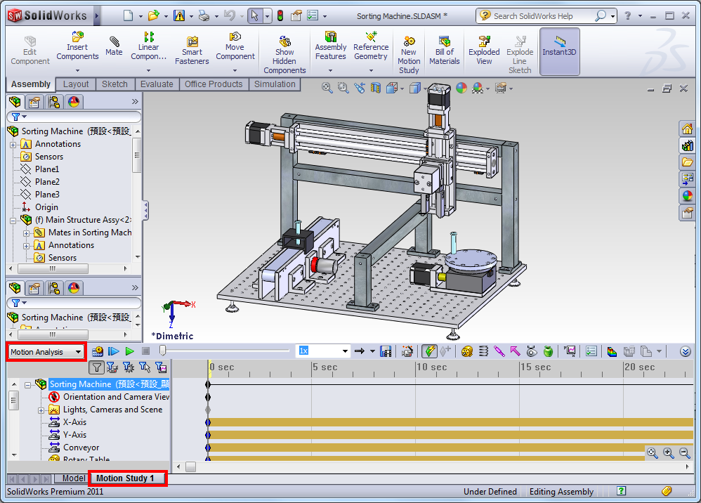
Additionally, drivers were developed to control stepper motors that could be combined with these boards (Pololu drivers).
To date, the installation of such a driver is required for each stepper motor of a printing device controlled by the Arduino + RAMPS bundle. RAMPS is able to work effectively when connected to up to five stepper motors.
Other All-in-one boards are equipped with special pads for Pololu drivers, which are widely used among users.
Many drivers have been developed that are compatible with the boards used in today's 3D printers. The most popular include:
- Driver A4988. The manufacturer produces the device in green and red colors, the maximum divider step is 1/16.
- There are purple and blue devices on the market. The main drawback of the model is the lack of a well-thought-out hold mode, which causes the device to get very hot. Such a chip is recommended to be installed only in conjunction with a powerful heatsink that can compensate for excessive heating.
 The maximum divider step is 1/32.
 - The original driver is made in Germany and the USA, but it is easy to buy a similar one made in China on the market. Copies differ from the original only in the accompanying piping - resistors, capacitors, etc., therefore, when using non-original devices, it may be difficult to select the voltage to power stepper motors. The device is characterized by quiet operation, background noise and engine sounds are minimized by manufacturers. The driver is equipped with its own chip, which is able to interpolate a 1/16 divisor to 1/256 without creating additional load on the processor.
- Made in China by Makerbase. A distinctive feature of the driver is the wide possibility of adjusting the microstep divider - from full to 1/128. There is no internal share in this driver model. The device is intended for installation on 32-bit boards only.
- Manufactured by Panucatt Devices. The driver is able to support microstepping from full to 1/32 and has well-thought-out protection against excessive voltage and high temperatures.
 Two model options are available: in the standard version, the voltage adjustment pin pad is shorted, so voltage adjustment can be made by the user in a manual setting format using a screwdriver and a multimeter. In the version with digital adjustment, debugging is performed at the software level and can only be supported by its own controllers - Azteeg X3, X3 PRO and X5 mini V3.
 - This model is also manufactured by Panucatt Devices. The driver is equipped with a sensor that protects it from overheating and high voltage and also comes in two versions - standard and digital. The device is based on the THB6128 chip. Designed for installation on eight-bit boards.
- A new version of the driver from Trinamic and Watterott. A special board via the UART interface is responsible for dividing the microstep. The built-in board allows you to connect the driver to a computer using a USB cable and configure it using your own software.
Installing and configuring the driver for the 3D printer
For the correct operation of the 3D printer, before starting it for the first time, it is necessary to install and configure the drivers.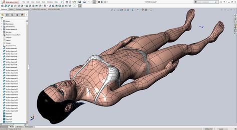
IMPORTANT! Before debugging, it is recommended to temporarily disable the anti-virus programs installed on the computer. This will help to avoid false triggering on files downloaded from external devices or the Internet.
The installation process takes place in several stages:
- Start the installation by downloading the driver file and running it. To do this, you will need to log in with an administrator account and run a file called "exe file". Next, following the instructions of the installer, complete the process and connect the 3D printer to your computer using a USB cable. The program will automatically find the device and assign it a COM port.
- Next, you need to download and install a program called Repetier Host. Once the download is complete, launch the program file and wait for the download to complete. After the installation is completed, along with the program, all the necessary accompanying programs will be launched, including slicer programs.
 During installation, it is recommended to uncheck the box next to the item about installing the Server utility, since it will not be required for further work and will take up device resources unreasonably.
 - The next step is to set up the settings for the personal computer. During this, a corrected interface in Russian will also be configured, the necessary scripts and an active link to the help section. At this point, the Magnum 3D and Magnum 3D Vase slicing profiles will be rewritten, so any changes made by the user should be renamed before starting the process. Otherwise, they will not be saved after reinstalling the program.
- After the installation is completed and the settings are set, you should run the Repetier-Host program and select the COM port to which the printer was connected. This step is mandatory because the installer automatically assigns COM3 to the device, which can interfere with further debugging.
- Next, following the instructions of the program, you need to update the downloaded scripts and restart the computer.
- During the reboot, you will need to press the F8 button and select the "Disable Driver Enforcement Signing" option.
- After downloading, you will need to do the following: open the Start menu, open the Settings tab, go to the Update and Security section and select Recovery. Then, going to the tab "Special boot options", you must select the item "Restart now".
- When the process is completed (the reboot should go through in normal mode), you should open the "Diagnostics" tab, go to the "Advanced Options" section, select the "Boot Options" item and restart the computer again. When the device reboots, a menu will appear on the screen with a choice of parameters that will be used by the system in the future.
IMPORTANT! In order to install an unsigned driver, you must disable automatic digital signature verification by selecting the appropriate item in the menu and pressing the F7 button.
There is an alternative method for installing the driver for 3D printers. It is used if the system to which you plan to connect is 64-bit. In this case, the instructions above will not work.
In this case, when connecting the CNC device to the computer for the first time, for an unrecognized USB Serial device, you must select the driver yourself by opening the "Modems" section and selecting the "Compaq" item, and then the Ricochet Wireless USB Modem devices.
Errors and how to avoid them
During the driver installation process, some errors may occur that prevent the process from completing.
The most common reasons for their occurrence are:
- Technical malfunction of the device. Even if the driver is detected by the system when connected to a computer, if it malfunctions, the installation will not be able to proceed correctly.
- There is a problem with the program being installed. The installer may have been corrupted during download or may have been infected with malicious code. The cause of errors may also be the absence of one or more files in the archive.
- The driver version does not match the installed device. Most often, such a problem is encountered by those users who install a driver downloaded from third-party sites, and not the one that came with the device when purchased. The error may be caused by the fact that the driver version does not match the specific device or operating system version installed on the computer.
- An attempt to install a new driver over the previously installed one will also cause an error. To fix the error, uninstall the old version of the program, and then start the installation again with a new file.
- The user is trying to install unlicensed software. If the downloaded driver does not have a special certificate that allows the operating system to recognize it, then the computer, when trying to install it, will give a corresponding error when the file is first launched.
Correct operation of a 3D printer is impossible without installing drivers - devices responsible for the movements of stepper motors.