Solidworks 3d printed texture
How to 3D Print with 3D Texture in SOLIDWORKS 2019
Since SOLIDWORKS 2019 came out, I have been obsessed with the 3D texture function. 3D texturing has been used in more art-focused 3D modeling programs like Maya or 3DS Max for a long time, but never before in a mechanically-focused program like I’m used to. Sometimes this function is referred to as “displacement mapping”.
Tutorial on how to use 3D texture to make 3D prints look amazingI love 3D texturing because it makes your 3D prints look amazing, and it helps hide the layer lines. Sometimes the printed part needs to include features like knurling which is very complicated to model, not to mention it’s not something that usually gets modeled anyway. SOLIDWORKS makes it really easy to apply them to your models. Let’s walk step-by-step through the process of making these awesome 3D prints.
Step 1: Find or Make an Image for your 3D Texture
Some images work better than others. Greyscale heightmap images are preferred by SOLIDWORKS but any black and white image should work. SOLIDWORKS uses the colors to identify the displacement in those areas. Larger image files will tend to take longer for SOLIDWORKS to process.
The best images for 3D texturing are black and whiteStep 2: Select faces you want to 3D texture
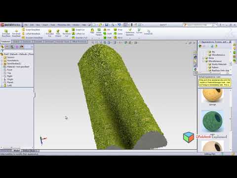
Select the faces you want to apply the texture to. I’m using a simple block for this tutorial, and selecting both flat and curved surfaces.
Step 3: Select Image & Create Appearance
Select the image from your computer to apply to the face. SOLIDWORKS will want you to save it as a new appearance file. Do that. If the image is already saved into your design library, then SOLIDWORKS will not ask you to save a new appearance file.
Step 4: Adjust Appearance
You can choose different types of appearance placement and mapping on each face.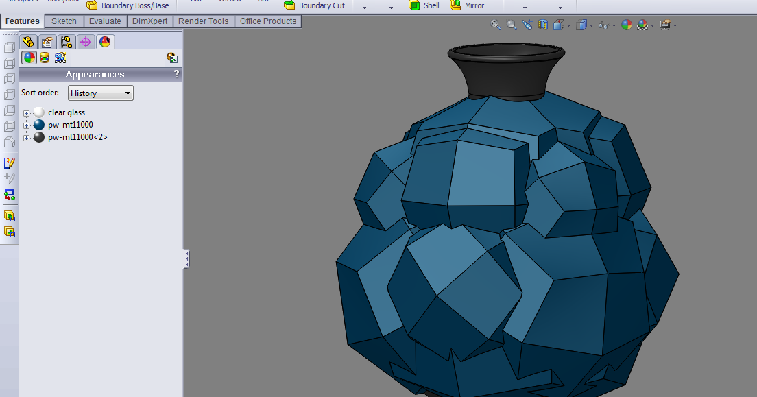 I like to use “automatic”, and “projection” most often. Flat faces are easy, but curved surfaces get more complicated. The “surface” mapping tends to work best with curved surfaces while “projection” is best for flat faces. You can scale, rotate and position the image pretty easily.
Step 5: Create 3D Texture
Go to Insert>Feature>3D Texture.
Insert>Feature>3D Texture
Every face that has the image applied to it will have a check box next to it. If you want every face with an image appearance on it to be textured, then check every box. Then, we can set the level of detail we want for each face, and the amount of offset. I like to use roughly 60% definition-or “detail”, and 0.5mm offset from the surfaces. By default, lighter colors will extrude from the model’s surface, while black will stay in line with the surface unless you turn off the option called “white up black down”.
Use the circled settings to adjust the detail (“texture refinement”) and depth (“texture offset distance”) of your 3D texture.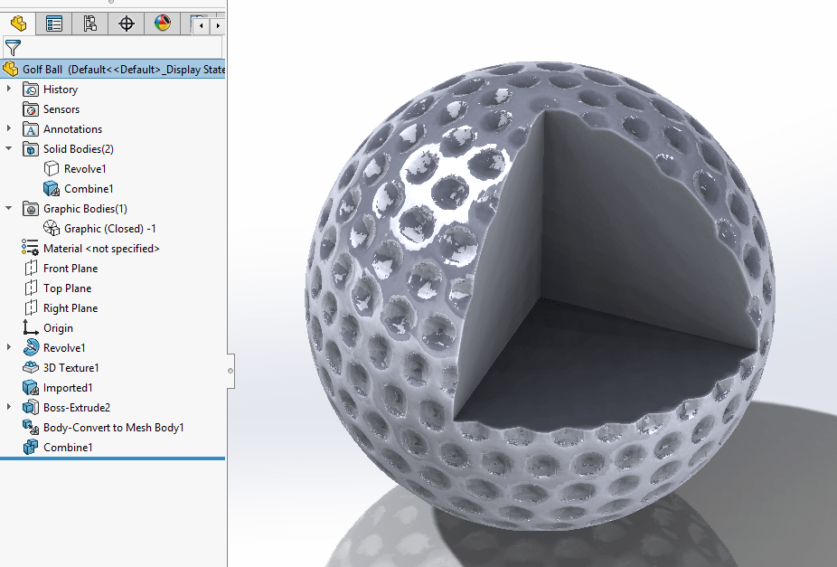
Conclusion
One thing to keep in mind with this technique, is that 3D textures come out better when they’re on vertical surfaces of your print. That way, we can get the most detail out of the textured surfaces by printing in small layer heights.
I’ve been using this awesome feature a lot over the past few months to add detail to 3D prints and hide the layer lines. I think it could be very helpful for anyone who wants to 3D print end-use parts that look nice. For anyone making prototypes, this technique can create a model that looks and feels more like the final product.
Want to have your design printed with a custom texture?
If you’re looking for short runs of parts, samples, prototypes, our FabLab is well equipped to handle what you’re looking for.
Learn about CADimensions 3D Printing Services
How to Use SOLIDWORKS 3D Texture Tool
SOLIDWORKS 2019 introduced a new tool called 3D Texture. In this article, we will explore what this tool allows us to do, when it may be applicable, and of course where to find it.
What Does the SOLIDWORKS 3D Textures Tool do?
The 3D Textures tool will transform a Textural Appearance into 3-dimensional geometry that can be manufactured using a 3D printer or other manufacturing methods. The grip bumps on a bicycle handle or pistol grip are examples of this.
How does the 3D Textures Tool Work?
The 3D Textures tool uses the color differences in a Textural Appearance to raise the level of the predefined color. We will explore this in much more detail later on.
What are Textural Appearances, and where can they be found?
A Textural Appearance is a grayscale image consisting of patterns using black and white colors.
To find one of these appearances, click the Appearances, Scenes, and Decals Task Pane icon, browse to the Miscellaneous folder > 3D Textures folder.
How to apply Textural Appearances in SOLIDWORKS
To add the appearance, browse to the 3D Textures folder and drag one of the textures to a model face.
In this example, I am dragging the Treadplate Bump texture onto a face of a cell phone cover.
Be sure to select Face on the pop-up Context Toolbar to avoid adding the texture to the entire body.
How to edit the appearance
If the appearance is not scaled to your preference, you can change this by editing the texture.
To do so. click DisplayManager, make sure View Appearances is highlighted, then right-click on the texture and choose Edit Appearance...
In the PropertyManager, click Advanced and then the Mapping tab. Under Size/Orientation, you can change the width, height, and angle of the appearance. For this example, I have set the width and height at .75in, and the angle to 45 degrees.
Where is the SOLIDWORKS 3D Texture Tool Located?
Once a Textural Appearance is added and scaled to preference, expand the Solid Bodies folder in the FeatureManager Design Tree, right-click and choose the 3D Texture icon.
Note: This will convert the model to a graphics body, so it should be last in the design process.
How to use the 3D Texture PropertyManager
Once the 3D Texture command has been enabled, the PropertyManager is displayed. This is where we will tweak some of the settings to transform the texture into 3-dimensional geometry.
- In the 3D Texture PropertyManager, expand Texture Settings and click the check box next to the texture you wish to convert to 3D.
- Enable the check box Convert this texture to 3D
- The check box White up Black down decides which color will be raised. For this example, the Treadplate Texture is white and the background is black. I have enabled the check box.
As you can see in the image above, the texture is poorly defined. The next set of options in the PropertyManager will allow us to refine the texture and give depth.
- Texture Refinement adds facets to better match the contours within the grayscale image.
- Texture Offset Distance specifies the maximum offset of the texture from the body.
- Maximum Element Size specifies the maximum size of the largest mesh facet in the mesh. Lower values create smaller mesh units and smoother models.
For the treadplate texture, I started off with a refinement of 50%, an offset distance of .03 inches, and a max element size of .2 inches. The image below reveals the results at these values.
When the values are increased for Texture Refinement and decreased for Maximum Element Size, the result will be a better looking mesh.
It is important to note that higher refinements will also place a higher demand on your CPU. For this reason, it may be better to refine in small increments until you get the desired results.
What about the Graphics Body?
Since this process does convert the model to a graphics body there are a few things to consider. In the FeatureManager Design Tree under the Graphics Bodies folder you will see one of two types:
- Indicates an open body and is not considered watertight.
- Indicates a closed body and is considered watertight.
To prepare the file for manufacturing you can convert the graphics body into a mesh BREP body.
- To do this, go to Insert > Features > Convert to Mesh Body
- Only closed graphics bodies can be converted to a mesh BREP body
Here is an example of the final model.
More SOLIDWORKS Tutorials
SOLIDWORKS Weldment Profiles & Weldment Tools Guide
SOLIDWORKS Mold Tools: Split Line & Parting Line Explained
How to Use Layers in SOLIDWORKS Drawings
SOLIDWORKS Mold Tools - Shut Off Surfaces, Parting Surfaces, and Tooling Split
Inserting Logos Into SOLIDWORKS Parts and Drawings
VIEW ALL SOLIDWORKS TUTORIALS
Slicer with simulation functions.
 ideaMaker major update / Habr
 Raise3D announced the release of a new version of the free ideaMaker software, the main feature of which was the texture creation function.
ideaMaker is one of the most advanced and versatile software available for most FDM printers. The program is constantly updated and improved. Among the latest important updates is the creation of textures for models.
In essence, the texturing capability turns the ideaMaker slicer into a 3D modeling program and allows you to skip time-consuming model processing in CAD programs, generate a 3D texture directly from a 2D image and apply it to the surface of the printed model.
ideaMaker allows you to automatically convert any image into a 3D texture that will be printed as the surface of the model. This greatly expands the possibilities for working with the appearance of products, making it more complex and unique. Patterns, shapes or logos can be transferred to the surface of the model.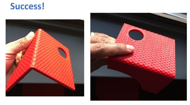 nine0003
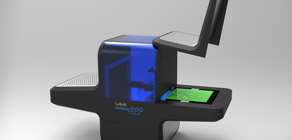
The creation function can easily turn any 2D image into a 3D texture on the surface of the model, and will facilitate the creation of products in many areas, especially where a unique design is required. For example, when developing digital products such as headphones, controllers, car interior parts, art products, home goods, architectural elements, computer mice and much more. With the new ideaMaker capabilities, you can easily create different iterations of the same STL model by applying multiple patterns. nine0003
In addition, the imposition of some textures can help increase the strength of the model and protect it from deformation.
A great example is textured with the Print+ headphone set, which is 3D printed in PLA.
Texture Advantage
ideaMaker Texture is easy to use and saves a significant amount of time compared to 3D modeling programs. This function is clear and accessible, including those who are taking their first steps in 3D modeling.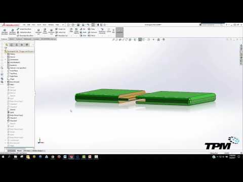 The ideaMaker online library has a large variety of different texture templates that can be imported with a single click. Also, any user can upload their own texture and print settings to the library. nine0003
All that is needed to use the texture is to import the .STL file into ideaMaker 4.1.0, then click the texture icon in the toolbar and select an image. Then adjust the texture overlay by the location and number of repetitions of the pattern on the model and other parameters until the desired result is achieved. The user can then slice and view the resulting 3D texture application on the surface of the model.
ideaMaker's texture creation is a new direction that opens up a number of unique possibilities for enhancing product design without the need for professional 3D modeling software. nine0003
A free download of the new version of ideaMaker is available here.
Here you can download textures from the ideaMaker library
Alexander Kornveits ,
Expert in the field of additive technologies, founder and CEO of Tsvetnoy Mir
How to get 3D textures from raster graphics
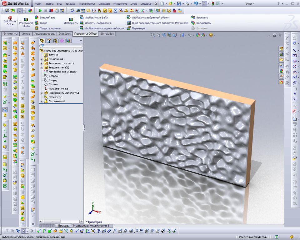
Apply to the surface of the model complex texture is not an easy task, especially if you solve it from scratch.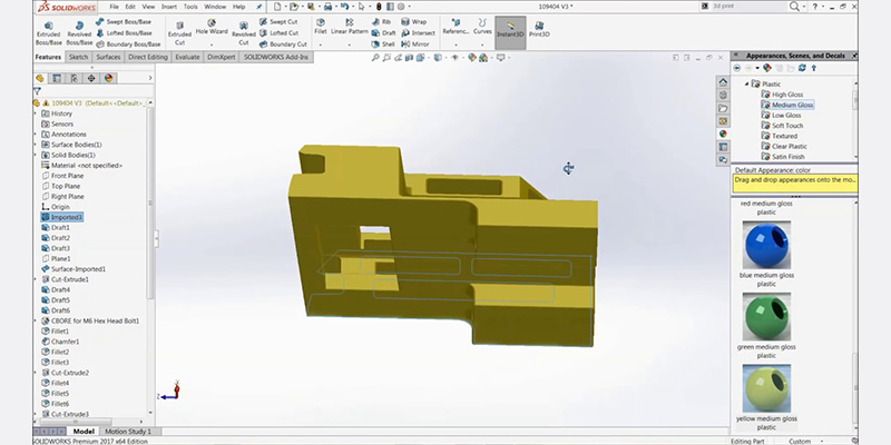 And if the surface is curvilinear or spline, then the complexity increases significantly. One of the new products in SOLIDWORKS 2019just designed to make this task easier. Now the texture can be easily obtained from a bitmap: the graphics file is converted into real geometry, which can then be used, for example, for 3D printing. This makes it possible to obtain a repeating relief pattern on the surfaces of bodies, to apply logos, etc. Let's see how to use this new feature.
Choosing an image for the texture
Let's start by overlaying the bump texture image (it can be a black and white file *.bmp, *.hdr, *.jpg, *.png, etc.) on the surface . In this case, you can select the faces of the model individually, or you can apply the texture to the entire model at once. There can be several textures, and before converting to a 3D view, some of them can be activated, and the rest - disabled. Using the standard projection function, we will model depressions on the surface of a spherical body.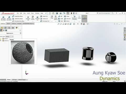 Let's place the image in a ratio of 1:1 in width and height. nine0003
Convert to 3D
To convert the texture to 3D geometry, right click on the body and select the tool as shown below.
You can now specify which textures should be 3D and adjust their size and position. Please note that the more small faces in the model, the more difficult it will be for SOLIDWORKS to draw them.
The performance at which the operation will be performed is determined by the settings of the graphics adapter. The further to the right the Texture Refinement slider is, the higher the density of the mesh. nine0003
In our example, if we increase the density value by 11%, the number of faces will exceed 30 million. The image of such a model is built on the screen for several minutes, and the file size becomes excessively large. The texture JPG file does not have much detail, so further increasing the parameter is pointless: this does not affect the smoothness of the model, it simply becomes more polygons.