3D printer inductive sensor
Auto Bed Leveling (ABL) Sensor Comparison – 3DMaker Engineering
One of the best upgrades you can add to a 3D printer to improve both performance and ease of use is an auto bed leveling sensor. Although they technically do not level the bed, they create a topological map of your bed and adjust the Z position of the nozzle to follow imperfections of your build surface for a more consistent first layer.
The first upgrade we do to all of our printers is solid mount the bed (remove the bed springs) and add an auto bed leveling sensor. This allows us to level the bed once and never have to worry about it again. When you have a print farm, the last thing you want to have to worry about is adjusting bed leveling knobs on a large number of printers.
Disclaimer: We currently sell a physical, hall effect type probe. We want to be upfront that we have not skewed our opinions based on this. The fact is, we tested each type of sensor extensively in our print farm and came to the conclusion that for our needs this was the most well-rounded option. Because of this, we decided to partner with a sensor manufacture to develop the 3DM Touch. We could have just as easily went with a capacitive or inductive style sensor which typically is much cheaper to manufacture.
If you Google “3D Printer Bed Leveling Sensors” you will find an endless number of manufacturers selling sensors of all shapes and sizes. To help simplify things we will break it down by sensor type instead of sensor brand. If you can understand the pros and cons of each of the technologies available it will help you determine the best one for your application.
Capacitive Sensor (ex. EZABL):
A non-contact sensor that can sense both metallic and non-metallic surfaces. This sensor works by monitoring the capacitance (how much energy the onboard capacitor can hold) which changes when an object is placed near its sensing face. It can detect any surface that has a die electric constant greater than air which should cover every build surface you will use (including glass).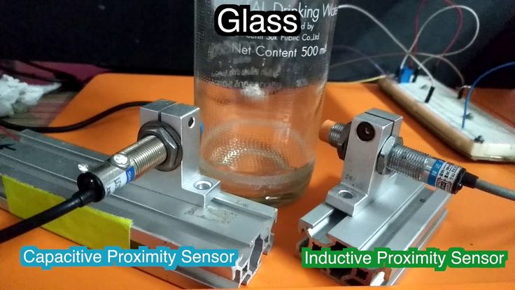 Another advantage of this sensor type is that it can probe extremely fast, saving you time during each print. Below is a basic diagram of how the sensor works.
One drawback is that while it can sense almost any surface, the distance at which it reads it will change depending on build surface type, temperature, and humidity. This is no problem if you only have one build surface and do not use an enclosure. If you plan to switch between different surfaces (ex. garolite, glass, PEI, polypropylene, etc.) like us, you will find yourself having to continually tweak your z-offset. Additionally, if you print in an enclosure where ambient temperatures vary, you will again need to adjust your z-offset.
Inductive Sensor (ex. P.I.N.D.A.):
This is another non-contact sensor, however, this type can only detect metallic surfaces. This means when the probe is analyzing a PEI spring sheet, it is actually mapping the spring steel and not the PEI surface you are printing on. This is usually not an issue, however, as the two surfaces should be relatively parallel with each other.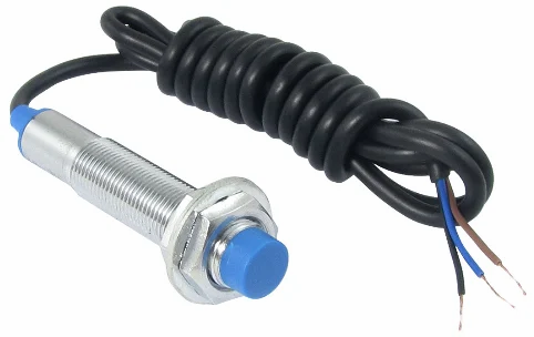 If you are someone who likes to print on glass, garolite, or polypropylene—you may want to look for another option as these materials will not be detected. Although these sensors look very similar to a capacitive sensor, they work based on a completely different principle. They use the electrical principal called inductance. In a nutshell, an inductor coil in the sensor creates a magnetic field that changes when a metallic object is within its sensing distance. Non-metallic surfaces do not affect the magnetic field which is why the surface must be metallic.
Similar to the capacitive sensors, their readings are affected by temperature and humidity changes, so be prepared to make adjustments if you expect to see large temperature shifts. Some printer manufacturers, like Prusa, have done their best to use onboard sensors to automatically adjust for ambient temperature changes but in our experience it’s hit-and-miss. We have MK3S printers where we calibrated the z-offset at room temperature, put them in a heated enclosure, and found that the z-offset was then completely incorrect.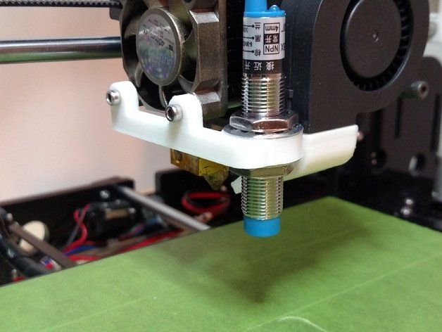 If you are not printing in an enclosure, the temperature compensation seems to work fairly well for minor changes in room temperature, which is what we think it was really intended to do.
Physical-Hall Effect Sensor (ex. 3DM Touch+):
This is the only sensor on the list that actually makes contact with the bed as a means of detection. Because of this, it is unaffected by temperature and humidity changes like the other two contenders. It functions by using a plastic plunger (pin) and a hall effect sensor to detect your build plate. As soon as the plastic pin makes contact with the bed, it is retracted and registered by the hall effect sensor. Also, there is a built-in solenoid that allows you to extend and retract the probe via g-code which gives you plenty of clearance while printing. Below is a diagram of how a basic hall effect sensor works. Please note, the plastic plunger has a magnet embedded towards the top which is what the hall effect sensor is actually monitoring.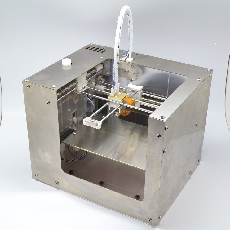
The main drawback of this sensor type is that it is slower compared to the other non-contact types. While there is only a few seconds difference per probe point, this can add up if you are doing a 7X7 (49 points) or greater grid pattern. The good news is that in Marlin 2.0 and newer, there is a feature called HSMode which allows you to probe nearly as fast as the others. The next issue is that it contains moving parts so, in theory, there is more that can break on the sensor. Luckily, the mechanism is extremely simple so there is almost no chance of it actually failing. The new plastic probe tips are also made to bend so if you accidentally crash it, you can simply bend the plunger back in place and get back to printing.
All testing was done with three brand new Prusa MK3S printers modified to accommodate the different sensor types.
Accuracy:
We wanted to test how well the three probes could continually reproduce a 0.24mm, single layer print without any other variables changing such as temperature or build surface types.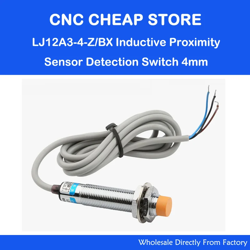 We tested this by using micrometers to adjust the z-offsets until all three printers were printing a true 0.24mm thick first layer. Once dialed in, we printed the test print 5 more times and measured the thickness in several spots using the same micrometers. All of the probes were able to reproduce a 0.24mm thick first layer consistently without any deviation. If the inductive and capacitive probes are more accurate, they did not translate into any real-world results. Our conclusion: in a controlled environment all three options will provide accurate readings.
Winner: Tie (Inductive/Capacitive/Physical-Hall Effect)
Versatility:
Our expectations: set the z-offset once and continually get a perfect first layer, regardless of the build surface type or ambient temperature. When you have several printers, you don't want to have to think about tweaking z-offsets every time your printer setup changes. This saves both time and frustration which, in our opinion, is the most important function of a bed leveling probe.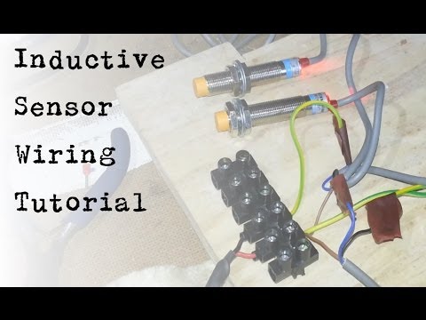
On paper, the two non-contact sensors should be the most accurate. Their lack of moving parts and the sensing method give them a leg up (and was shown by Thomas Sanladerer on his YouTube comparison). However, when you throw in real-world variables such as different build surfaces and drastic temperature changes present in an enclosure, the Physical-Hall Effect type sensor comes out head and shoulders above the rest.
Similar to the previous accuracy test, we set our first layer height to 0.24mm and then printed an object that was only one layer thick. We then removed the print and measured it with micrometers and made adjustments until it was exactly 0.24mm. Once the z-offset was adjusted to produce a true 0.24mm first layer, we then heated the enclosure to 35°C and hit print without adjusting anything. The 3DM Touch was the only one that was able to reproduce the same 0.24mm first layer while the other two failed to have a successful first layer. We did this 4 more times and the results were the same each time.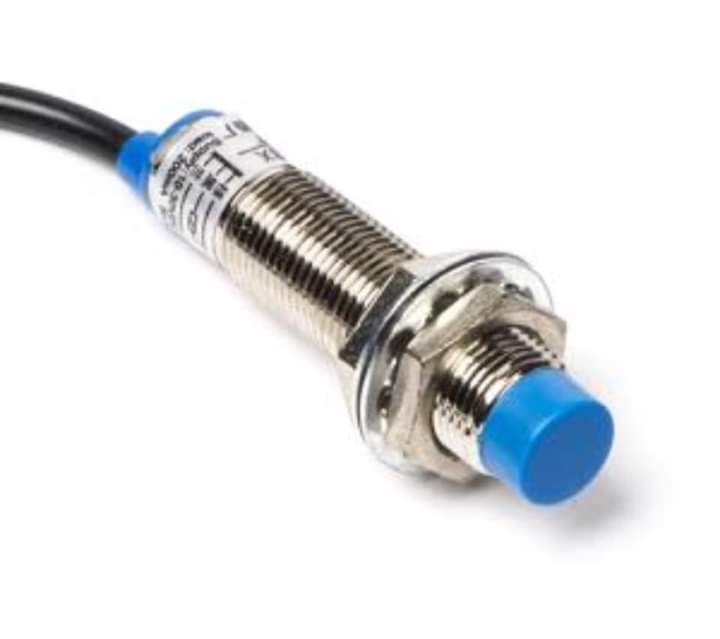 The non-contact sensors just weren’t able to give the same z-offset reading with the large change in temperature.
The next test was about switching between build surfaces. We did not test the inductive sensor as it can only sense metal and knew it wouldn’t be able to handle this task. For this test, we again adjusted the z-offsets on the two printers to produce a 0.24mm first layer using a spring steel build surface. After this, we then swapped out the spring steel build surface for a polypropylene plate. As expected, the 3DM Touch printed the same 0.24mm first layer while the capacitive (EZABL) sensor gave us a first layer height of 0.17mm which is an error of 30%. This is because even though the capacitive sensor can detect polypropylene, it detects it at a different distance than spring steel. If you plan on using different build surfaces, we recommend staying away from the inductive sensors as they will fail to detect everything except metal.
Winner: Physical-Hall Effect Sensor
Probing Speed:
Both non-contact sensors are considerably faster than the physical probe. They don’t have any moving parts so no time is required to cycle the probe up and down. As mentioned earlier, Marlin 2.0 has introduced HSMode for the 3DM Touch which has helped increase probing speed, however, even then it will still be ~10% slower to probe the same number of points. If probing speed is extremely critical in your application, an inductive or capacitive sensor might be the best choice for you.
Winner: Tie (Inductive/Capacitive)
Durability:
After testing each sensor type (multiple of each, over several months) none of them showed any signs of having issues with durability. Some argue that the 3DM Touch sensor has moving parts so it, in theory, could wear out. We are confident that your machine would need to be replaced long before the plunger mechanism wears out. The old BLTouch probes had metal tips that would get damaged if you crashed your machine but the newer ones all use “breakaway” plastic tips that deflect if crashed.
Winner: Tie (Inductive/Capacitive/Physical-Hall Effect)
Because the 3DM Touch is a lot more complex in its design, it tends to also be the most expensive.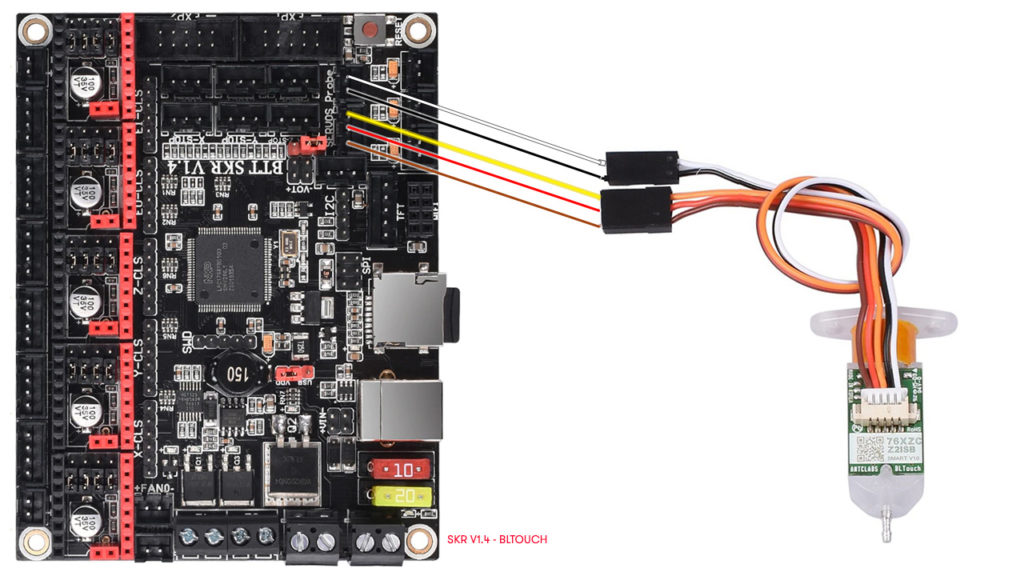 There are also very few manufacturers who produce them which is also a driving factor of cost. Quality capacitive and inductive sensors, on the other hand, can be found for less than $10. This is approximately a third of the cost of 3DM Touch-type probes. If you are on a tight budget and still want to add a bed leveling probe to your machine, both the capacitive and inductive sensors will be a great choice.
Winner: Tie (Inductive/Capacitive)
All three sensors seem to do a more than adequate job as long as you don’t plan on switching build surfaces or changing ambient temperatures drastically. Casual users who are on a tight budget will likely be extremely happy with either a conductive or inductive type sensor.
If you are a 3D printing “super-user” and have the extra budget, we would recommend the 3DM Touch as it requires the least amount of calibration in the long run. It handles everything from build surface changes to large temperature variation without ever needing to do any additional calibration.
Each user is going to have a different set of requirements for their printing needs. For us, the 3DM Touch made the most sense; for others, it may be a capacitive or inductive sensor. We hope that this article helps clear up any uncertainty about the various options available and will help you make an informed decision for your own needs. If you have any questions about areas we did not cover, please feel free to contact us and we will do our best to provide answers.
-3DMaker Engineering
9 myths and 12 sensors tested! – Tom's 3D printing guides and reviews
There are many options for a 3D printer’s bed sensor and even more misconceptions about what they can and should do. So after a ton of testing with a custom-built precision test apparatus (TM), 9 myths about these sensors have been examined – and we got a ton of data about how precise each one can be!
Twelve options to sense the surface of a 3D printer’s bed. Twelve solutions to the same problem. Twelve sensors that are all different.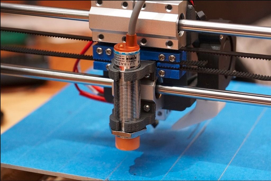 But there can only be one! Well, actually, each one of these has an upside, so let’s see what they can and can’t do. Myth busting 3D-printer style!
Essentially these should all do the same thing: When using autoleveling on a 3D printer or even on other machines that need their tool to be at a perfect distance from a workpiece, like a PCB router, these sensors probe a few different points on the surface and then compensate for any misalignment of the bed or workpiece. Since the sensor itself is the only input the machine gets about how the surface is aligned or deformed, it’s kinda critical that it senses stuff reliably and can even detect your surface. The easiest option are inductive sensors, but those only detect metals and are useless for glass, then you’ve got optical ones, which can detect any surface as long as it’s not totally transparent, mechanical ones that physically extend to the surface and touch it, and lastly capacitive sensors that will detect every surface and then some.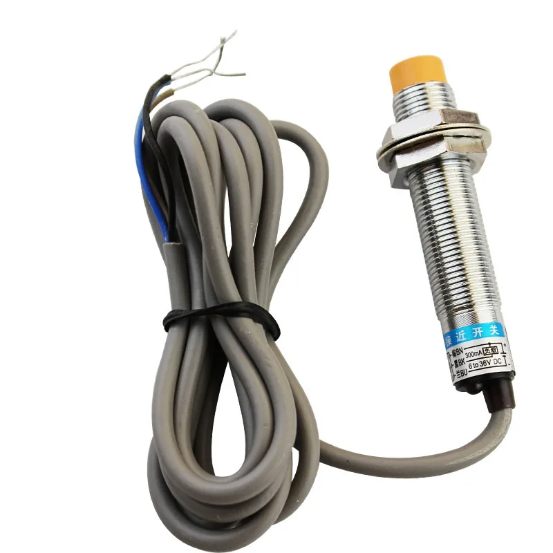
To test their repeatability, I built this assembly that should provide a near-perfect linear motion for testing the sensors. Essentially, it’s an IGUS W rail, which as a sliding mate, should have a better repeatability than ball bearings, and the backlash these typically have doesn’t matter much since gravity is essentially pre-tensioning things here, then we’ve got another IGUS part, a 2mm pitch trapezoid spindle attached to a 0.9° stepper motor the two shafts here are touching inside the coupling, so we’re not getting any springiness. Again, to take care of any tipping effects on the rail, it’s mounted off-center. The entire thing is driven with an MKS Gen board that was literally sitting in the “scraps” bin, and a few lines of Arduino code. And yes, you can still run standard Arduino code by itself on any 3D printer board that would otherwise run the Marlin firmware or similar. All it does is to run the sensor into the surface, backs up by a bit and then does that again 41 more times.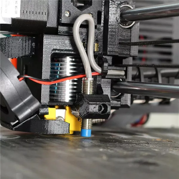 In the end, it reports the standard deviation of all measurements, which essentially tells us what sort of precision we can expect from each sensor.
To check that this construction even worked as intended, I mounted a steel rod to the carriage and let it close a circuit as it touched the aluminum block, and that came in with a repeatability much better than one micron, and basically, it was never further off than a single microstep. Yes, the microstepping might not be perfect, but it’s still an indicator that this apparatus works pretty well for these measurements.
So the units I’ve got lined up here are four different industrial inductive sensors, the smaller 2mm trigger distance, 5V type, a 4 and 8mm type and the Prusa PINDA probe, and yes, Prusa definitely has the smallest and shortest one of them all. Also in the category of inductive sensors is the one from the BQ Hephestos 2, but that one turned out to be defective, so I couldn’t include it. The capacitive ones are also industrial types, with 8 and 20mm sensing distances, this huge guy was actually pretty expensive in comparison at around 8 bucks, and even worse, it also didn’t work.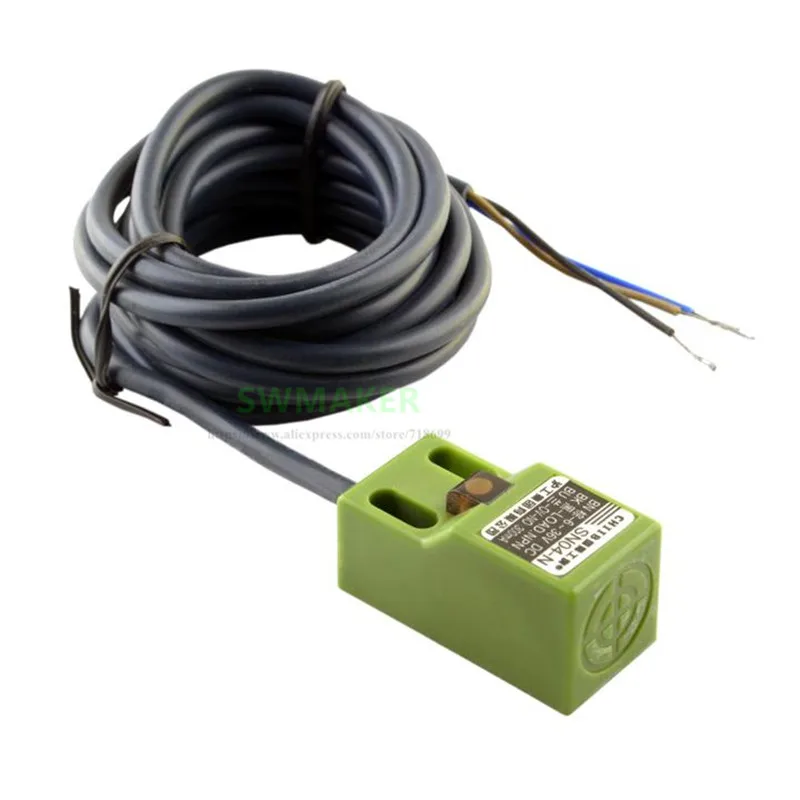 Bummer. Mechanical probes are the BLTouch and a standard microswitch with and without the lever, the BLTouch retracts on its own, while a switch like this will need some sort of servo to lift it up, which will introduce inaccuracies on top of what the sensor itself can do. And lastly, the optical sensors are David Crocker’s (DV42) infrared probe I got from Think3DPrint3D and a Sharp sensor that outputs an analog voltage according to how far away it senses an object, which is really cool, but needs a comparator to generate that on/off signal the board requires.
So that’s how we’re going to do it, let’s get to mythbusting!
That’s actually one that’s a bit more complex than it might look like at first sight. Glass is transparent, obviously, at least to the naked eye. But because these sensors work with infrared light, what they see could be completely different to what we see. These sensors work based on reflected light, so having a surface that is glossy like this could throw them off as well.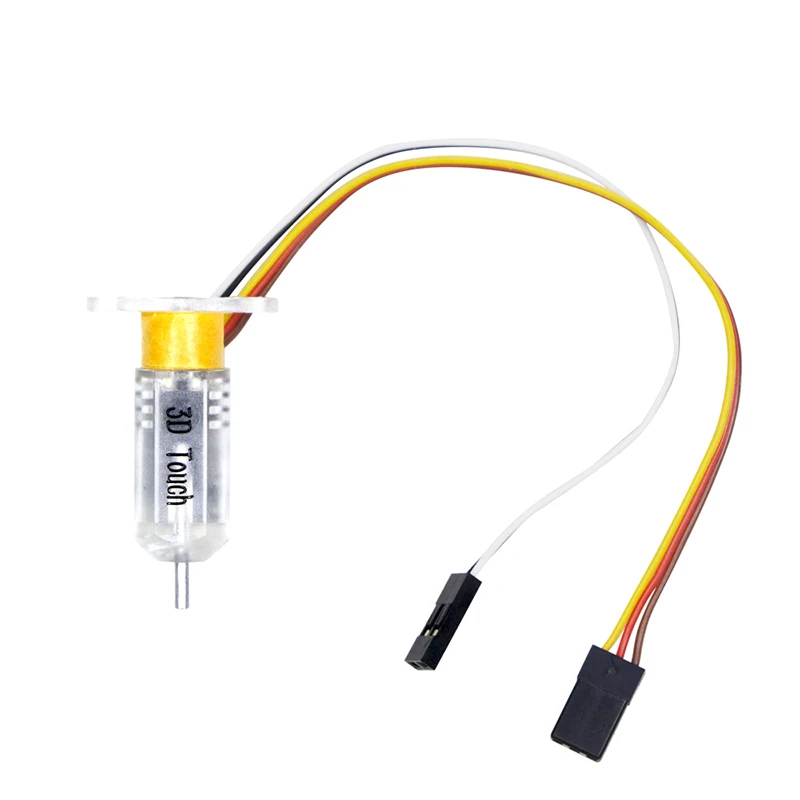 Now, the simple answer is yes, both the optical sensors can detect that sheet of glass. David Crocker’s sensor easily detects the glass, but the Sharp sensor gets thrown off track quite a bit. First off all, it requires a much larger distance to trigger at all, and even then it started drifting and eventually smashed into the glass. The custom sensor did trigger reliably against glass, but still came with a huge penalty in precision: The readings onto glass had a tolerance fifteen times as large as the ones onto an opaque block. So while it works, it’s not something that is really advisable.
Ok, this one is actually easy to test. Out of all the 6 to 36V probes, none worked on 5V except the 8mm capacitive one. And even then, it was much less sensitive than on 12V and only triggered against metal parts, while with the higher supply voltage and a voltage divider on the output, it reliably also triggered against printed parts and had a larger trigger distance than on 5V.
So that one is busted.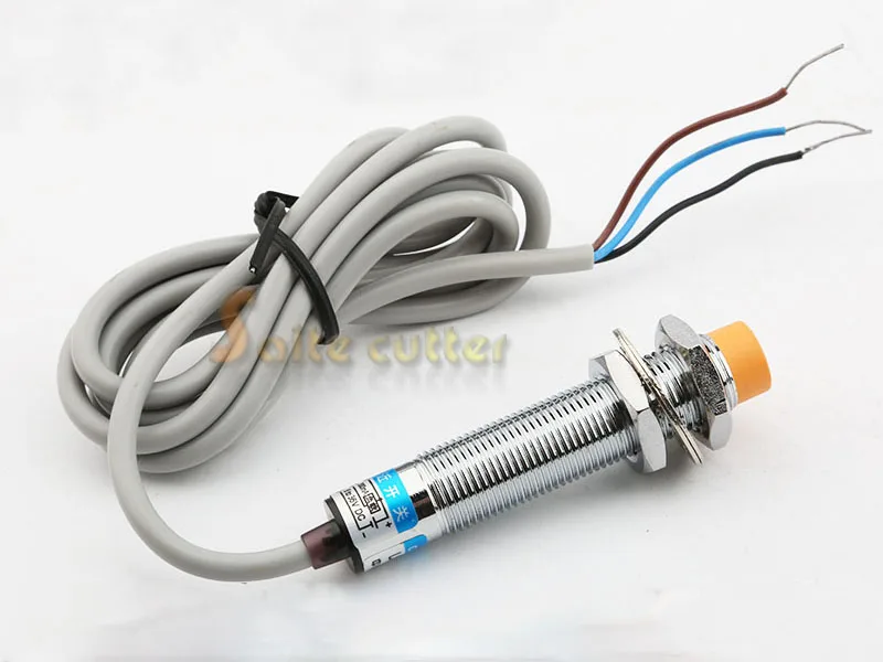
So the theory with capacitive probes is that they sense pretty much anything – Plastic, glass, wood, metal, humans, etc. The problem is, things like moisture in the air also influence the readings – in theory. So as a really simple test, I let the system do 21 measurements and then just started breathing over the sensor. And oh boy, did that throw it off. Almost instantly, it started triggering about 200µm earlier – that’s 0.2mm, so basically a full layer height off target. So even if you had a less extreme humidity change, it would still throw the sensor off by a significant amount. I also did the same with the inductive sensors and while they did show a marginal change, it was always in the single-digit micron range, which might as well have been from thermal expansion. Speaking of the topic, the capacitive sensor also showed, by far, the greatest deviation when blasted with a hairdryer on low.
So are capacitive sensor unreliable and imprecise? Well, if you look at the base reading in a consistent environment, they aren’t that bad, but as soon as anything changes, you will run into issues.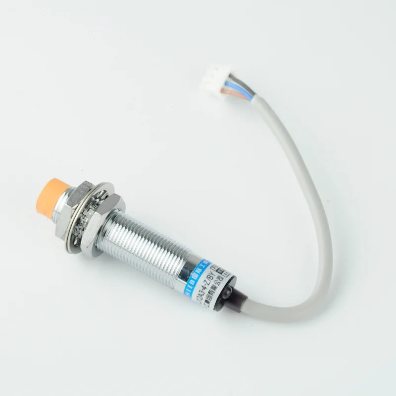
There are a few things that go into this – first off, some sensors, like the Sharp optical one only take a reading a few times per second, so by the time they trigger, you might already be past the point that would be the perfect spot. The same thing might be true for the printer’s firmware, which only reads values every now and then. The code I’m using is checking the sensor after every microstep, so that shouldn’t be an issue. But still, sensor delay etc still are. So every sensor was tested at two different speeds – 1.35mm/s and twice as fast, so 2.7mm/s, which is about the range you would expect a normal Z-axis to move at. And basically every single sensor was less precise when run at the faster speed. They all showed about 20% better repeatability at the slower speed, some a bit less, some a bit more, so while that’s not going turn a great sensor into an unusable one, or vice-versa, it’s still a considerable improvement if you just need that extra bit of precision.
So you might have noticed the effect that when you run the autoleveling cycle with the bed cold, the nozzle height will end up slightly different than when probed hot.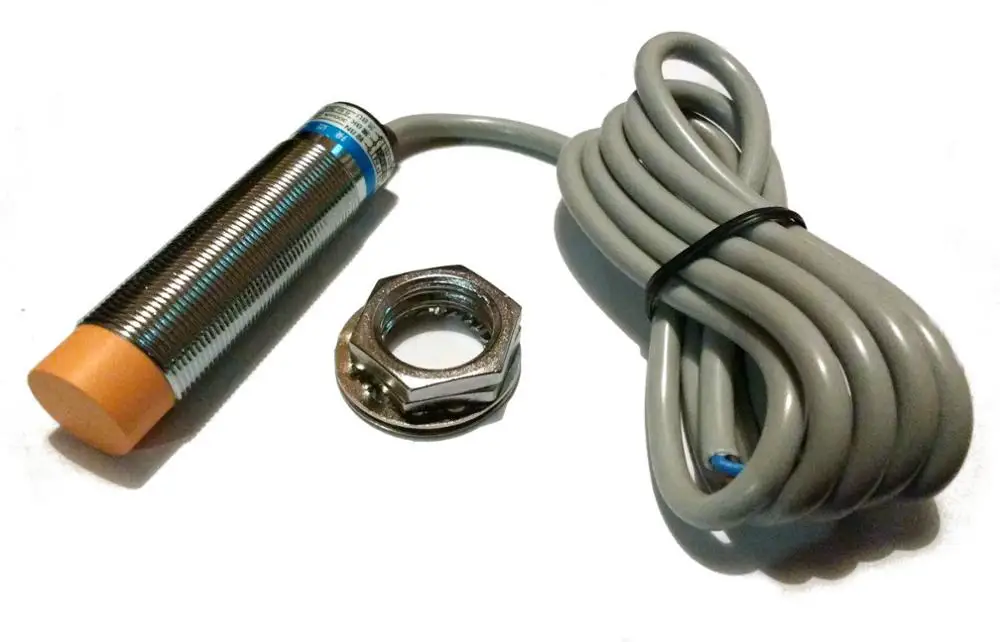 And this is very real effect, but after testing all the relevant sensors, I’m not quite sure that the sensors themselves are actually the problem there. It looks like the larger the trigger distance is, the larger the temperature drift is going to be.The inductive and optical ones were all decent, maybe not the 8mm inductive one, but the others are all at least usable when heated up. Though what also played into this was the apparatus simply heated and expanded, too, so the measured trigger point unavoidably moved back, too. What could also play into this is that at higher temperatures, copper and aluminum are less conductive, so for the sensor, it’s as if there was a thinner sheet of material, which shortens the trigger distance.
So the myth is that if you want the advantages of an inductive sensor, you can simply use some aluminum tape, even on the bottom of a glass sheet and the sensor will still trigger. So I used some standard aluminum tape, and the 4 and 8mm inductive sensors do trigger against just the roll of material, but none of the inductive sensors actually triggered against a layer of tape, even on the top surface of a glass sheet.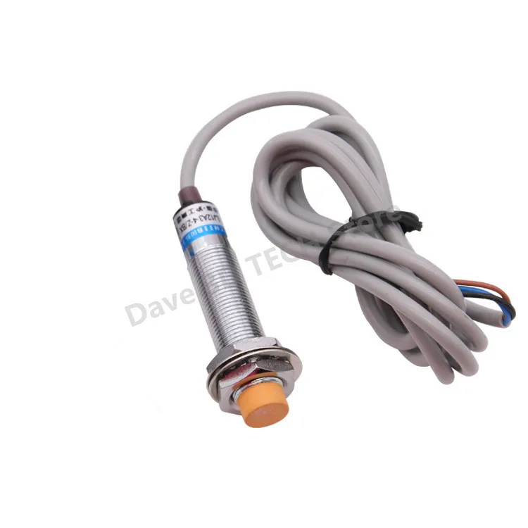 So while multiple layers might work, they are going to add some thickness, and even then, you’re only going to get a fraction of the nominal trigger distance.
Update: It looks like there are different types of adhesive aluminum tape available. Some types with a thicker aluminum layer seem to work much more reliably according to feedback from viewers.
And that leads us into…
While none of the industrial sensors are actually made to detect a set distance precisely each time, they can still be incredibly good at it. For the inductive sensors, I had 2, 4 and 8mm types, and they all performed virtually identical. They all achieved sub-micron repeatibilities, except for the 5V, 2mm type, and even that one was better than 2µm. So that’s busted.
Before I try and explain why this is the case and end up with half the viewers and getting bored and the other half getting ready to roast me, let’s just stick to the facts: Yes, inductive sensors do lose quite a bit of their trigger distance, even against a solid block of aluminum.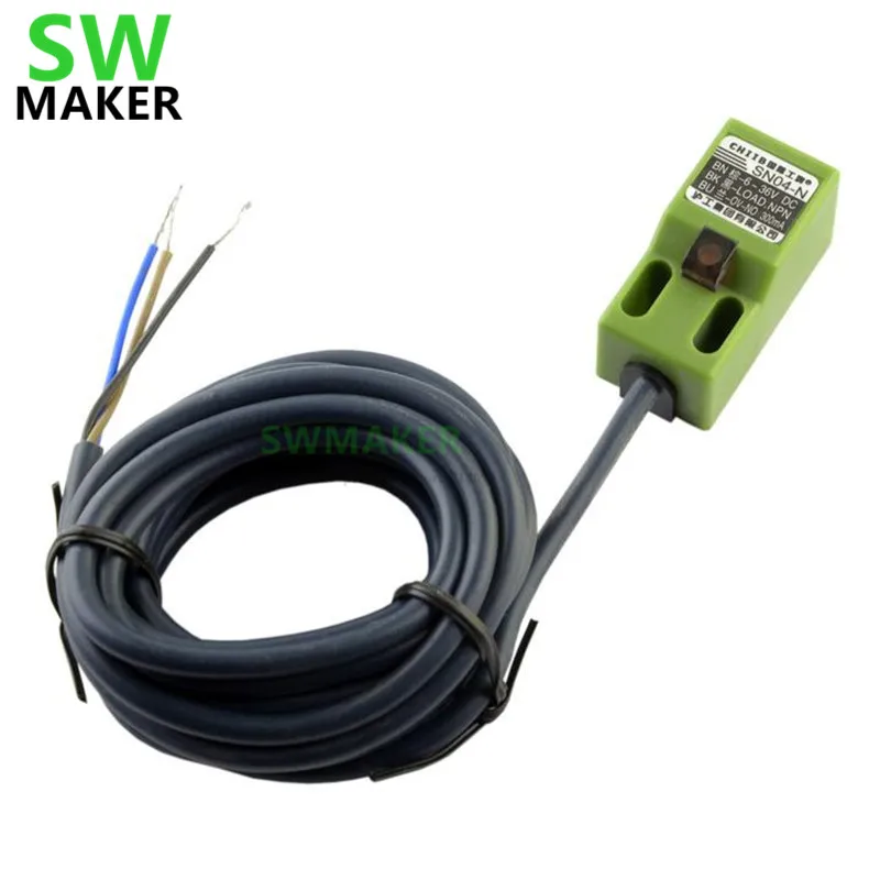 The distance the sensor says is against iron or steel, and with aluminum, you get about half of that. Capacitive sensors aren’t affected by this.
And lastly,
And this one is from the BLTouch kickstarter campaign – the sensor measured in with a standard deviation of about 2.5µ. Let’s take a step back and look at what the standard deviation means. Say you have a bunch of measurements and you plot out how many of them are how far off. Typically, noisy sensors like show a normal distribution, which looks like this. All the standard deviation says is that about ⅔ of the measurements are better than that standard deviation range. So with a bed leveling approach that uses just three points, on average, two of them will be measured more precisely than the standard deviation, and one of them will be worse. In turn, this point then, again, has about a ⅔ chance of falling within the range of two standard deviations, which means that, statistically, every three prints, that 50µ sensor is going to have be off by more than + – 100µ or 0.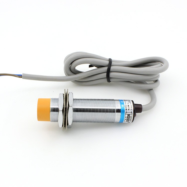 1mm. And if you’ve ever played around and experienced the difference 100µ can make to the first layer of a print, you’ll probably agree that that’s too much.
Now, of course, a more precise sensor can still have those measurements that are far off, but it’s much less likely to happen.
So if you look at the measured standard deviations of the sensors I’ve tested, I’d say they are all very usable, maybe with the exception of the SHARP optical sensor and the capacitive one, everything else is, like, really good. Out of those, the BLTouch performed the worst, but if you take it a bit slower, it’s still way more than good enough.
So yeah, that’s the story behind all the different sensor options. What surprised me was how precise the inductive sensors turned out to be, I was expecting them to be much noisier. What I’d also like to retest is the Sharp sensor, this one is the analog type, but they are also making ones just trigger at a set distance, and I think that might make it a bit less noisy.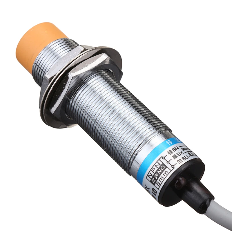
🛒 M8, 2mm inductive sensor (5V)
🛒 M12, 4mm inductive sensor
🛒 M16, 8mm inductive sensor
🛒 M16, adjustable capacitive sensor
🛒 M16, 20mm capacitive sensor
🛒 David Crocker’s IR sensor
🛒 SHARP analog sensor
🛒 Microswiches
🛒 BLTouch
Inductive auto level sensor and glass table. (For example SN08-N)
Personal diaries
Follow author
Follow
Don't want
11
Hello brothers and sisters!
My history in the world of 3D printing began not so long ago, at the beginning of the year only.
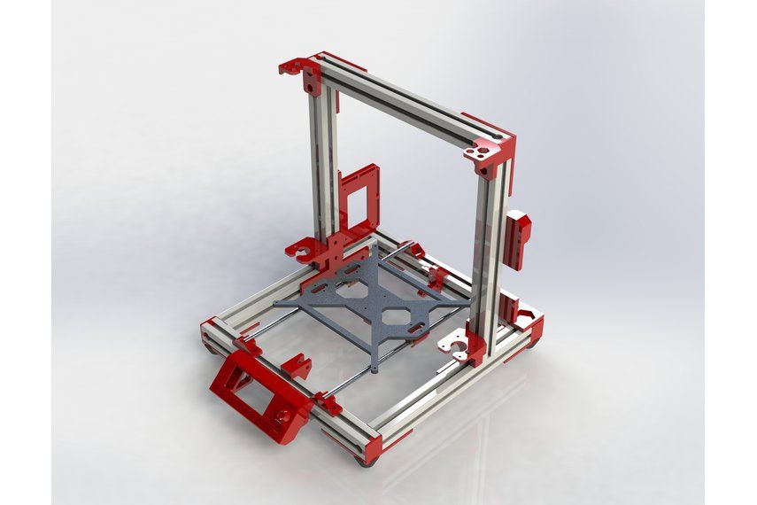
And it began with a printer called here FLSUN 3D Metal Frame Large Print Area 3D Printer , but in the common people FLSUN Cube , which, among other things, was equipped with an inductive auto-level sensor and an aluminum print table that offered a coil of double-sided Kapton.
And, as every skein of tape is supposed to, one day it ended, and I was already quite used to the auto level, and I didn’t want to refuse at all, just like changing the existing and properly working sensor to Bltach analogues.
So after the kapton ran out, a sticker (Frosted Heated bed Sticker) was bought from fuseths, by the way, these are one of the few sellers who have 300 * 300mm stickers. The sticker worked great, the ABS parts not only did not come off during printing, it was not a trivial task to remove something with a large contact area. And because of this, the sticker suffered quite a lot, from my hands, cuts somewhere, cracks somewhere and a few marks from the parking of the heated nozzle. nine0003
I was too lazy to bring a new sticker from China, so it was decided to take glass, or rather a mirror.
This is where my attempts to increase the range of the sensor began.
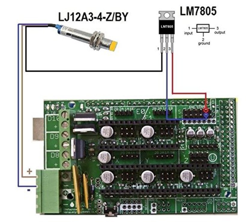
I came across an article by overseas bourgeois that, by connecting the sensor separately from 12V, the distance increases right up to as much as 6mm, which, in principle, with a mirror thickness of 3-4mm, was very good, and in principle enough.
I won't describe the experiments in this field, but in the end, due to the curvature of my hands, the case ended in complete failure, I almost burned the ISS and the BP.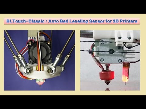 nine0003
With a few exceptions, during all these "adventures" I noticed that the sensor reacts to iron objects in a slightly different way than to aluminum ones.
The sensor worked on an aluminum table at a distance of 3mm, while on any iron thing at a distance of about 7mm!!!
And quite by chance I had the cheapest protractor made of some kind of tin, only 0.2 mm thick, on which it was checked, and since I already knew where protractors are sold, and a couple of calls to stores selling various metals were a success was not crowned, an immediate raid was made on the nearest stationery store. nine0003
Purchased pieces of iron were placed under the auto-level points, a mirror was placed on top, and lo and behold! Everything worked great!
So, if someone has this sensor but wants to use glass, it's up to you!!!
PS.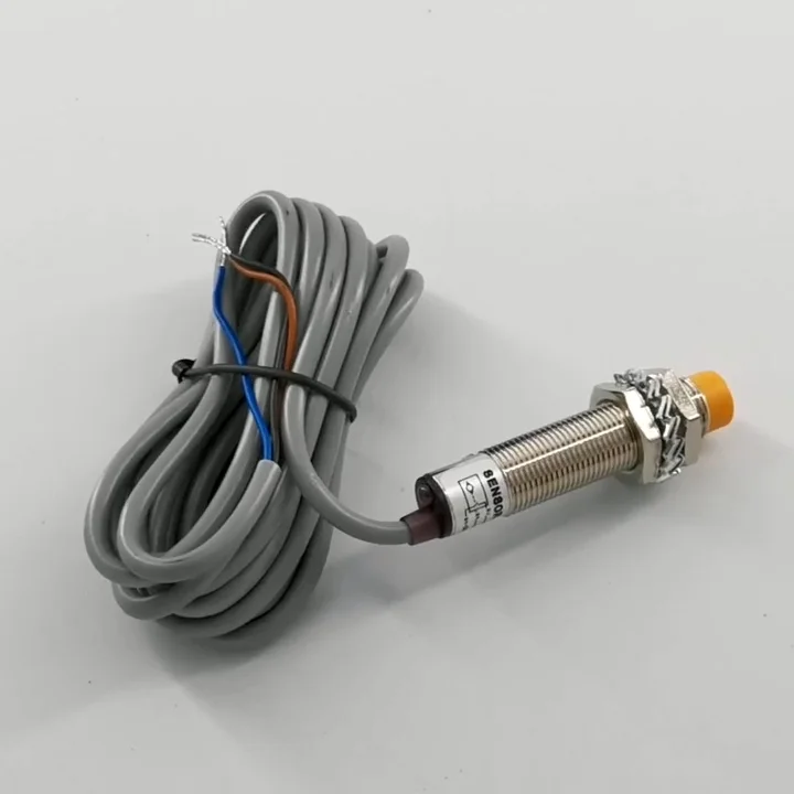 I apologize for the quality of the photo, video and text, and I also offer my sincere condolences to all the victims! Once again, thanks for your attention!
Follow author
Follow
Don't want to
11
all you need to know
3DPrintStory Reviews BLTouch sensor for 3D printer: everything you need to know
Automatic table calibration is a fairly common feature in desktop FDM 3D printers. However, most 3D printers with automatic table calibration use a non-contact inductive sensor, which is easy to install, operate and configure. These inductive sensors work well with metal 3D printer tables, but tables made from other common materials such as glass are virtually invisible to inductive sensors.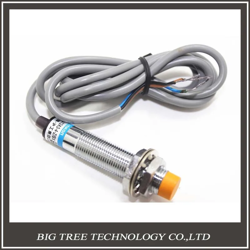 nine0003
Perhaps it is because of this lack of inductive sensors that many people hear about BLTouch sensors: if you need to use a non-metallic 3D printer slot base but need automatic calibration, these sensors are a great option. Another plus of these sensors is its high accuracy. BLTouch raw readings have one of the lowest standard deviations of any sensor type for automating 3D printer bed calibration.
In this article we will look at the BLTouch sensor, its advantages and how to use it for a 3D printer (by the way, there are many clones of BLTouch sensors, but the original design belongs to Antclabs from South Korea). nine0003
What is a BLTouch sensor?
According to Antclabs, the original manufacturer of the sensor, "BLTouch is an automatic table calibration sensor for 3D printers that can accurately measure the angle of the table surface." This sensor works on any type of surface, be it metal, glass, wood and others.
The 3D printer table tilt level sensor itself has a rather complex design.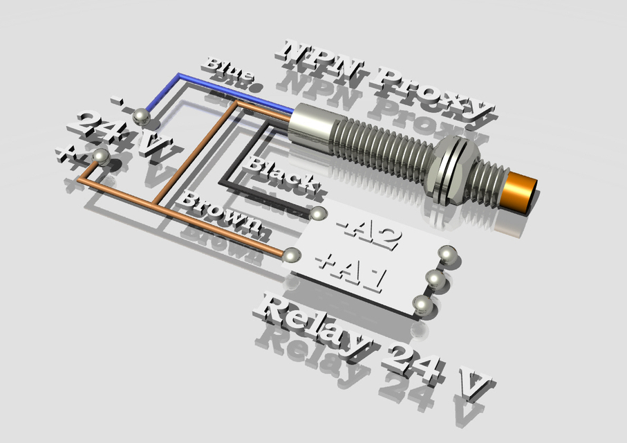 It consists of a microcontroller, a solenoid switch and a handpiece that is in direct contact with the table. The original BLTouch uses a Hall sensor for high accuracy, and this sensor, combined with the physical handpiece, allows it to be used with many types of tables. nine0003
In a sense, this sensor is equivalent to a microswitch mounted on a servo. When the tool head is lowered to "return" the nozzle in the Z-axis, the table pushes the tip slightly up, the Hall sensor is activated, and then the tool head rises.
TheBLTouch is one of the most accurate and reliable sensors out there, so it's no wonder some manufacturers like MakerGear and CraftBot use this device on their high-end 3D printers. nine0003
Now that we know exactly what we're dealing with, let's compare the BLTouch with the other two types of sensors.
Different types of sensors for automatic calibration of the 3D printer table
Inductive sensor
The key difference between the inductive sensor and BLTouch is that the BLTouch sensor physically touches the table during the calibration process.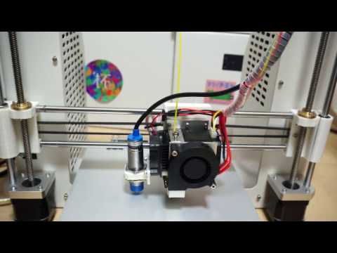 The inductive sensor uses currents induced by magnetic fields to detect nearby metal objects, so there is no direct physical contact with the table. nine0003
But therein lies the problem: induction sensors only work with metal tables, as they only work when they come into contact with metal. So if you are using glass, then this type of sensor will not work for you.
Microswitch (mechanical limit switch)
Don't discount the old-fashioned physical microswitch either. Compared to the BLTouch, this sensor is less accurate and possibly less reliable in the long run because the measurement is dependent on physical parts that can wear out over time. nine0003
However, these mechanical switches outperform other options when it comes to cost and ease of setup. Since mechanical switches are very simple to implement, easy to set up and cheap, they have found quite a wide application.
Alternatives
Pinda Probe
Pina Probe is a sensor developed by Prusa Research that is an induction sensor with a thermistor to account for changes in bed temperature.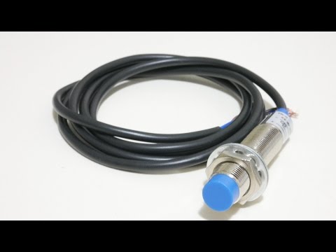 The Pinda probe is specially designed for the Prusa line of 3D printers, which have special dot-mounted calibration markers on the table that help with alignment and skew correction. nine0003
This is said to be a very accurate sensor for 3D printers, and although there aren't many numbers on the internet, the reviews seem to be positive. So it is worth considering that this is a good option if your 3D printer has a metal table.
Ezabl Pro
Ezabl Pro is a capacitive sensor manufactured. It comes with a connection board that uses an optical isolator to prevent high voltage damage to the motherboard in case of connection errors.
In terms of accuracy, it can measure to one thousandth of a millimeter, which is what 3D printers need. Ezabl Pro also has useful features such as double shielding that prevents any interference from other signals.
The main disadvantage of Ezabl Pro is the cost, which is about 65 dollars. But this sensor can work with glass tables.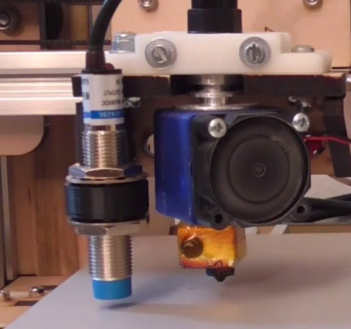
Piezo Sensors
Piezo Sensor uses the piezoelectric effect to detect changes in force, pressure or strain and convert those changes into an electrical impulse. Precision Piezo is one of the few companies in the UK that makes piezo sensors for 3D printers. They have an accuracy close to 7 microns, which is pretty accurate for a 3D printer. nine0003
The advantage of the piezoelectric sensor is that a nozzle can be used as a sensing element without the need for additional components. In addition, a piezoelectric sensor can be placed on the print head or under the pressure platform. As for the price, it is in the same range as BLTouch.
BLTouch Sensor Setup Basics
Before you start modifying your 3D printer for BLTouch, you need to work out the following points. nine0003
Mounting the sensor
The BLTouch sensor must be installed as close to the print head as possible. You can find many designs available for download on the internet.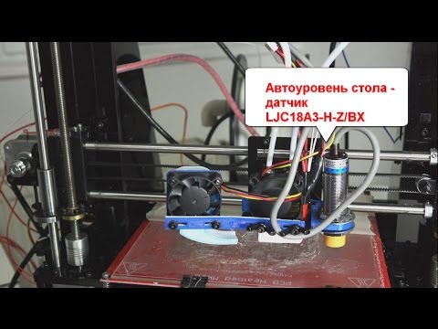 If you would like to design the mounting structure yourself, be sure to read the BLTouch documentation to take into account the overall dimensions of the sensor.
Some users have experienced a problem where the nozzle hits the table on one side and prints perfectly on the other. The reason for this is that the BLTouch is mounted at an angle to the nozzle. Therefore, when designing and installing equipment, make sure that the BLTouch is mounted perfectly at right angles and aligned with the nozzle. nine0003
After installing the sensor, be sure to record the distance between the BLTouch sensor and the center of the nozzle in both the X and Y directions.
3D printer firmware configuration
To run BLTouch, you will need to change the 3D printer firmware in several places.
We used Marlin firmware version 1.1.9 which was updated in March 2020. Enter the marlin.ino file and go to the configuration.h tab.
The first step is to activate the BLTouch sensor by declaring it. Remove the two slashes to uncomment the define statement:
#define BLTOUCH
The next step is to set the BLTouch offset using the X and Y distances you should have measured when you installed the sensor. Z-shifting may seem like a more complicated procedure, as the BLTouch probe protrudes below the nozzle for direct measurements. You will need to find the distance between the sensor and the end of the nozzle when the sensor is fully extended.
Also, since the probe goes below the nozzle, the offset must be negative. We recommend setting it to around -2.5 for safe first runs and then adjusting. You need to change the values of the following lines to match your numbers:
#define X_PROBE_OFFSET_FROM_EXTRUDER 30 // X offset: -left + right [nozzles] #define Y_PROBE_OFFSET_FROM_EXTRUDER 20 // Y offset: -front + back #define Z_PROBE_OFFSET_FROM_EXTRUDER -2.5 // Offset Z: -below + above
After you're done with the offset, you'll need to choose a table alignment type. You can choose from five different compensation methods, below we will give an example using the bilinear method as it is easy to get started with. nine0003
To select the appropriate option, uncomment it by removing the slash. Please note that only one option can be left without comment. Your code should look something like this:
//#define AUTO_BED_LEVELING_3POINT //#define AUTO_BED_LEVELING_LINEAR #define AUTO_BED_LEVELING_BILINEAR //#define AUTO_BED_LEVELING_UBL //#define MESH_BED_LEVELING
You can also set the number of mesh points that you will base your calibration on. Default is 9points that form a 3-by-3 grid along the x and y axes. The number of points can be increased for more accurate results, but keep in mind that the probing time will also increase proportionally.
#if ENABLED (AUTO_BED_LEVELING_LINEAR) || ENABLED (AUTO_BED_LEVELING_BILINEAR)
// Set the number of grid points per size.
#define GRID_MAX_POINTS_X 3 #define GRID_MAX_POINTS_Y GRID_MAX_POINTS_X
Testing
After setting up the firmware, you will need to check if the BLTouch is working properly by doing a basic test. Once it's complete, you can start adjusting the Z offset. There's a great video from 3DMakerNoob that walks you through the process step by step. nine0003
Slicer setup
Be sure to add the G29 command to your Gcode right after the G28 command.
Troubleshooting
Troubleshooting
The creators of the original BlTouch at Antclabs mentioned that the original sensors come with a QR code built into the circuit board on the back. Other Chinese manufacturers, called TL Touch and 3D Touch, are also known to produce lower quality products, resulting in poorer quality. When buying online, be sure to purchase from one of the authorized resellers that are listed on the Antclabs website. nine0003
Known Issues with BLTouch Sensor
The latest version of BLTouch V3 had issues with Creality printers where it did not work properly.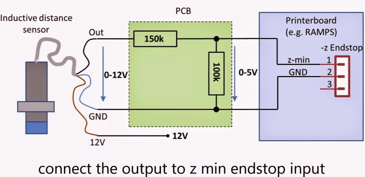 The Marlin firmware developers worked closely with Antclabs and determined that certain changes needed to be made to the firmware.
An excellent tutorial video on how to fix this problem was made by Teaching Tech. After making changes, many users finally solved the problem.
BLTouch Disadvantages
Although the BLTouch is an extremely accurate level sensor, it also has several disadvantages.
When using the BLTouch, it is important that there is no debris on the surface of the bed. A mechanical sensor detects the surface of the table and any damage or debris on the surface will result in inaccurate readings.
The BLTouch is also known to suffer from interference from currents in the hot end heater wires. This interference causes incorrect BLTouch readings. The Marlin firmware has a special line of code that will help you turn off the heaters while the sensor is triggered.