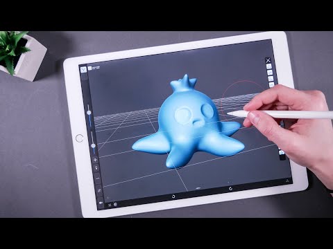
Shapr3D 3d printing
How to Design for 3D Printing
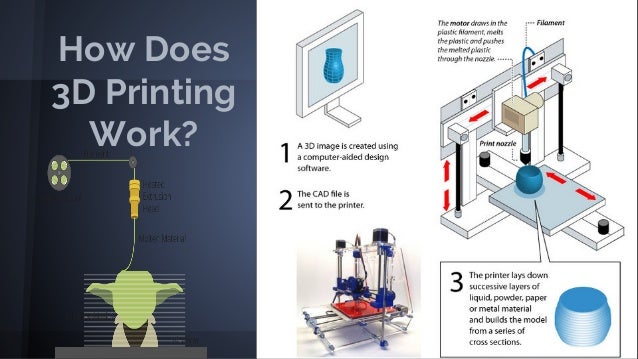
Once reserved for high-end research, the evolution of 3D printing now encapsulates everything from rapid prototyping to full-scale manufacturing.
For product innovators, industrial designers, and budding 3D printing enthusiasts ready to take design concepts to tangible products, this guide will walk you through the how-to’s of mastering quality 3D printing and finishing your prototype for presentation.This will allow you to create high-quality 3D concepts and products in record time.
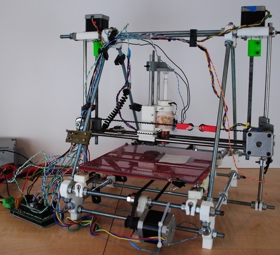
To demonstrate that you can achieve high-end results economically, we printed each model in this guide with a Fused Deposition Modeling (FDM) printer.
Following is an overview of the topics covered. Read through in order or skip ahead to the section most relevant to your process.
- Improving Print Quality: your choice of printing equipment is directly linked to how fast your product prints and the level of detail that you can achieve
- Perfecting Design Parameters: in order to be printable, your geometry needs to have volume and manifold geometries
- Managing Supports: beyond a certain point, your printed material won't be able to print onto thin air (surprise!) and requires designed 3D printed supports, which will affect the look of your final object
- Model Orientation: the direction that the material is layered to create your object and how it will impact the final look and feel of your object
Though it may seem daunting at first, using 3D printing your designs to test and iterate product concepts trims the design to manufacturing timeline, making the learning curve worth the time investment, even in the short run.
To hone in on leveling up your design workflow, rapidly developing new ideas, or launching a successful business with a product concept, go through this A-Z checklist of design principles for 3D printing to cover your bases before pressing print.
With the aim of speeding up manufacturing, we recommend Shapr3D CAD software to create 3D models within a plans-for-your-next-move user interface that markedly cuts your design time.
Download Shapr3D
The Principles in Action
Wayne State University’s industrial design professor, Claas Kuhnen, gives an overview of creating a cohesive design process and addresses common design-to-print issues in this video.
The Right Modeling Mindset
Keep in mind when 3D printing that the digital version of your design will have to deal with the laws of physics when it comes out of your 3D printer's nozzle.
A tangled print of a 'T' shaped overhang succumbing to the punishing power of gravity
Overhangs that stretch effortlessly out into the ether on your iPad screen may come crashing down into a melted plastic mess from your printer. Perfectly concentric holes in your model may better resemble a deflated basketball in the real world. You may find that the thread you're trying to fit that screw into has nothing to do with the size of the thread on the screw anymore.
To anticipate and prevent these challenges, keep each guide item in mind during your design process.
Printer Setup
One of the biggest factors that will affect your 3D prints is the nozzle. The nozzle size and material will influence the strength, print time, and quality of your final product. While this is only true for FDM methods, similar resolution settings and issues will still appear with other 3D printing methods.
Nozzle diameters generally range between 0. 1 – 1.0 mm. When you're selecting a 3D printing nozzle, you're deciding how much filament is extruded and how fast, which will naturally produce different results. While a smaller printing nozzle (<0.4 mm) predictably extrudes less material than a larger printing nozzle (>0.4 mm), the impact this will have on your print is more complex.
The standard nozzle size that most 3D printers come with is 0.4 mm. This size lets you print layer heights between 0.1 - 0.3 mm, so you can manufacture detailed objects in a reasonable amount of time.
Tip: When choosing a printer head, determine the final use case. Use a larger nozzle to print strong objects quickly. Give more detailed prints a smaller nozzle. The following are some general tips to guide you:
Use larger nozzles (>0.4 mm) for:
- Printing things fast. Larger nozzles equal larger flow rates and more material deposited.
- Increased toughness. The energy absorption increases to 25% when printing objects with 0.
 6 mm nozzle versus 0.4 mm nozzle.
 - Printing with abrasive filaments. Smaller nozzles easily clog, making them a difficult tool for printing coarser filaments - opt for a larger nozzle in this case.
- Models with low print resolution. Larger nozzles work best for prints without thin or fine details because they print thicker layers.
Use smaller nozzles (<0.4 mm) for:
- Small details. Print highly detailed models with small nozzles to extrude material more finely.
- Many features. Printing with a smaller nozzle takes more time, so it's only worth your while if you are manufacturing a more decorative piece and have a lot of time. Plain objects make more sense to be printed with a larger nozzle. Example applications for small nozzles include jewelry, text printing, or miniatures.
- Low layer height. Generally speaking, layer height should be 80% or less of the nozzle diameter, so a smaller nozzle will require lower layer height.
- Easily removable supports. Using smaller nozzles will result in a thinner support structure that can be more easily detached from your object after the print.
Dual Extrusion Printers
Dual extrusion printers have a second nozzle and extruder, so you can print parts using two different materials, switching between filaments as needed.
With a dual extrusion printer, you can combine a standard material with support materials. By printing supports with a different material, easily remove or dissolve them from the final print without leaving any marks. Dual extrusion printers also let you print using two different colors, or reinforce one printing material with a stronger one.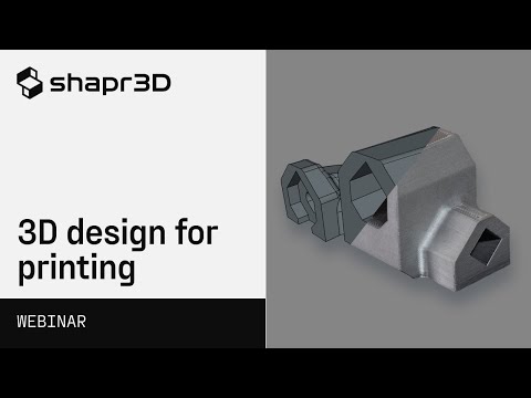
Nozzle Material
The nozzle material will also affect your print quality and speed so let’s look at the different options available.
Brass Nozzles
These are the de facto standard for most FDM 3D printers. This nozzle material provides good thermal conductivity and stability. Keep in mind that while it's the most common, it can't handle all types of filaments. Brass nozzles are best for non-abrasive filaments including PLA, ABS, Nylon, PETG, TPU, and more.
Hardened Steel Nozzles
Unlike brass nozzles, hardened steel wears less when printing abrasive materials like carbon fiber, glass fiber, metal-filled filaments like steel-filled, iron-filled, brass-filled, and other exotic filaments.
The wear-resistance of steel nozzles beats brass nozzles 10 times over, but the possible presence of lead in the nozzle makes them unfit for printing anything that will come in contact with food or skin. Stainless steel nozzles make a strong lead-free alternative for FDA-approved products, as well as a compatible option with light, abrasive materials.
Ruby Tip Nozzles
Ruby tip nozzles have a brass body with a ruby tip. The ruby tip increases the nozzle's durability and the body maintains good thermal conductivity, making this nozzle type the most precise, albeit expensive, option for regular use.
Slicing Software
Choosing the right slicing software for your designs and machine is also paramount. Many users will use Cura as it’s free, easy-to-use, and compatible with a huge range of machines. However, if you’re a professional user you may opt-in to purchasing something more comprehensive like Simplify3D.
For most users a free slicer will completely suffice. However, paid software can help speed up your manufacturing process and optimize the 3D printing process on the whole. When doing large scale additive manufacturing or highly detailed models a paid slicer can save time, costs, and in some cases increase the print quality too.
What's the best slicing software to use?
The best free slicer is Cura, and the best paid option is Simplify3D. The fundamental capabilities of Cura typically meet the average hobbyist’s needs. Professionals who benefit from more options should opt for a paid software for higher quality and faster outputs.
Materials Used
When carrying out your design you’ll also need to consider the material that you’ll be printing with. Later on this article we discuss design and production factors that are of significant importance. However, these are recommended with common materials in mind.
For example if you’re using flexible materials, reinforced plastics, or metals the processes and design requirements can be opposite ends of the spectrum.
Design Parameters
Before you print, aim to make your design watertight by eliminating discontinuities on the surfaces of your 3D model
If you're 3D printing a model that you exported from Shapr3D, you can check this off your list! The app ensures solid model design, without non-manifold intersecting surfaces.
If you're modeling using surface modeling software, you'll want to post-process your work, clean up any holes and check for any of the kinds of intersecting surfaces or shared edges (collectively called non-manifold geometries) listed below.
Manifold geometries
Using manifold geometry makes for a successful print. . An easy way to understand manifold geometry is by understanding non-manifold geometry.
Non-manifold geometry means that when the 3D shape is unfolded, the normals of the 2D shape don't all point in the same direction due to a shared edge or two faces connected at a single point.
Tip: To make sure that your model is printable, check for any of the following errors and adjust them to create a manifold shape:
T-type non-manifold geometry
If three faces share a single edge, make it printable by adding volume to the third face or deleting it completely.
Model of a non-manifold object with connecting faces attached at a shared edge
Bow-type non-manifold geometry
In this instance, multiple surfaces connect at one point and don't share an edge. Either disconnect the two geometries or delete one of them.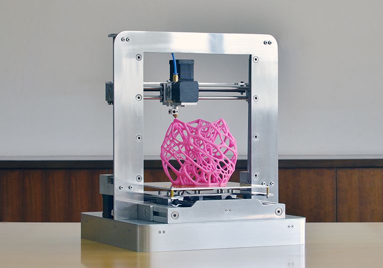
Model of a non-manifold object with connecting faces attached at a single point
Non-manifold geometry also occurs when there's a shape without volume.
Open geometry
In order to print a geometry, it needs to have a volume, so a shape with “missing” surfaces or no volume isn't viable. This would be the equivalent of asking your 3D printer to print one straight line and expecting it to come out in 3D.
You can create volume in your model by adjusting the wall thickness or adding additional surfaces to your geometry.
Model of an open geometry without volume that is adjusted for 3D printing by increasing wall thickness and/or adding sides.
Wall thickness
Wall thickness goes hand-in-hand with non-manifold geometries, as we saw above, geometries without volume can't be manufactured. Walls that are too thin make small parts on the model unable to be printed or very fragile, with a high chance of breaking.
Assess your printing material and the height of your wall to determine whether it needs additional support.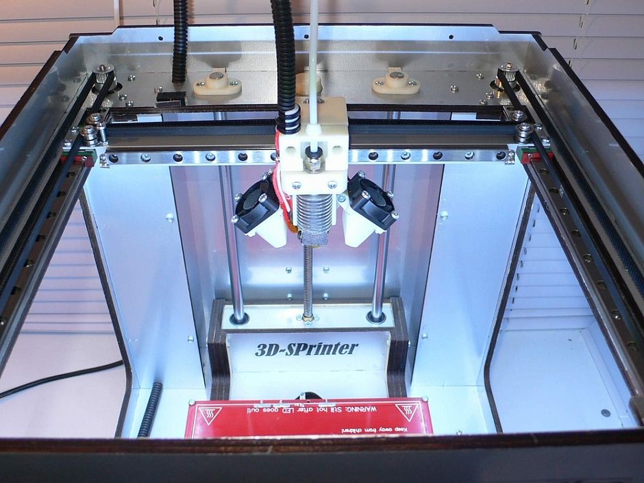 A wall that's already bolstered by ribs or webs (we'll get to those soon) can be thinner than a freestanding wall.
Tip: Wall thickness should typically be two or three times the nozzle's width. Walls with thicknesses greater than 0.8 mm can be printed successfully with all processes.
Thick Wall Layers - Two layers with a thicker layer sizeStart with a strong base
Adhesion is a huge difficulty with 3D printing. If your model, or even a part of it, doesn't stick directly to the 3D print bed when the first layer is printed, it could detach and warp your print resulting in much plastic, time, and dreams down the drain.
Tip: avoid large flat surfaces and round the corners of your 3D models to enhance the success of a clean print
Printing with too high heat and not allowing the first layer to cool properly will increase the risk of a bulge, and make it hard to fit pieces together. Affectionately named ‘elephant's foot,' this mostly appears with large parts where the weight of the object pushes down on the first layer.
Two 3D prints of the bottom of a water bottle with the version on the right showing a slight bulge, or 'elephant's foot'
Add a ‘raft'
Sidestep this issue by adding a raft for your "foot" to land smoothly on. A raft in 3D printing is a flat surface area made up of horizontal latticework, added beneath your part. It helps eliminate the elephant's foot and improves adhesion to the printer bed.
Adhesion Raft Support - Adding a raft in Lulzbot's CURA slicer software
Work with a ‘brim'
You can also avoid your model tipping overby creating a brim underneath it. A brim is a skirt attached to the edges of the model printed with an increasing number of outlines to create a large ring. Brims create suction and hold down the edges of your part by helping it stick to the bed. They're much faster to print than rafts.
Warm up your nozzle with a ‘skirt'
Finally, you have skirts. Sometimes, an elephant's foot is the result of an unleveled build plate or incorrect nozzle height.
Skirts surround the part, but don't actually touch it, and they help warm up the extruder by establishing a smooth filament flow. By observing the skirt quality, you can adjust any leveling issues before printing your model.
Adhesion Skirt Base Support - Adding a skirt in Lulzbot's CURA slicer softwareTip: Besides printing with a raft, skirt, or brim, you can also lower the bed temperature by 5° C increments or, as a last resort, alter your model by adding a 5° chamfer on the bottom edge of the print to mitigate the bulge.
Overhangs and Support Material
Overhangs are fun to design and hard to print—here's where gravity puts up a fight.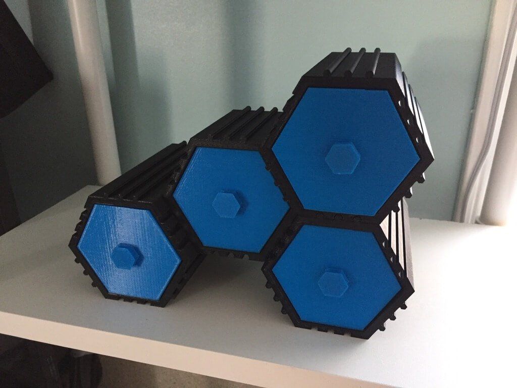
An overhang that stretches out beyond 45 degrees requires you to include supports so that your build doesn't tip or lose form. There's nothing wrong with supports, but unless you print with a soluble material using a dual extrusion printer head, they'll probably leave a mark when you take them off.
Tip: As a good rule of thumb, you can get away with about 1-2 widths of a print path without support. Everything else will require printed support.
While supports are doable, they're not always easy to remove and will likely leave a rough spot or mark on your print.
3D Printing Overhangs - 3D printed model illustrating to what extent overhangs can print without supportsThe image below shows a 'Y' model with arms that begin with an overhang less than 45 degrees. Notice that further up the arms where the overhang reaches beyond 45 degrees and would require supports, the integrity of the print breaks down.
Follow the 'YOTH' rule
- A Y-shaped overhang that’s less than 45 degrees prints easily without any need for support.
 If it's over 45 degrees, count on adding supports.
- “O” shaped overhangs, or holes in most cases, create more concentric circles with supports included
- "T" shaped overhangs beyond a 1-2 vertical layers require supports
- “H” shaped overhangs depend on the size of the bridge between the two vertical geometries. Check your printer and print material to see how long of a bridge you can print without supports.
Designing support Structures in your slicer software
If you do need supports, create them in your slicer software. Here's what that looks like on Lulzbot's free CURA slicer interface.
You can also design custom supports in your modeling software that are easier to snap off and take up less surface area. Conical supports taper at the top to support your print while printing faster and using less material.
Advanced 3D Printing Supports - Conical supports designed in Lulzbot CURA's slicer softwareRegardless of size, removing supports and polishing your prototype will take some work after your print.
Removing Support Material By Hand - The aftermath of supports removed from a 3D printed threaded water bottle capPrinting holes
Holes are a special kind of 'overhang,' that 3D printers struggle to print. These shapes require the machine to create a round shape by layering materials on top of each other. Because the final layer at the top of your circle will be straight, the end result is a hole that's not quite round and doesn't quite match the diameter of the hole in your model.
You can print out the hole with the slightly flatter top, and use a screwdriver or similar tool to round it out after it's finished.
Teardrop and slot designs for holes
To deal with the pesky issue of holes, you can also try designing a few additional tweaks in your model. One alternative is to model a teardrop-shaped hole in your geometry. This way, you can use the hole for its intended purpose without having to drill out the additional layer at the top of the hole.
Teardrop Designed Hole - Teardrop designed hole in 3D printing geometryThis technique minimizes the need to use supports, but only when you orient the part facing upwards, which limits object rotation.
3D Printing Holes With Support - If your object has to be rotated in a specific direction a teardrop-shaped hole may not be feasible — in this case, add supports to your holeIn the same vein, you can add a slot underneath a hole that you need to insert a rod into, which allows the hole to expand.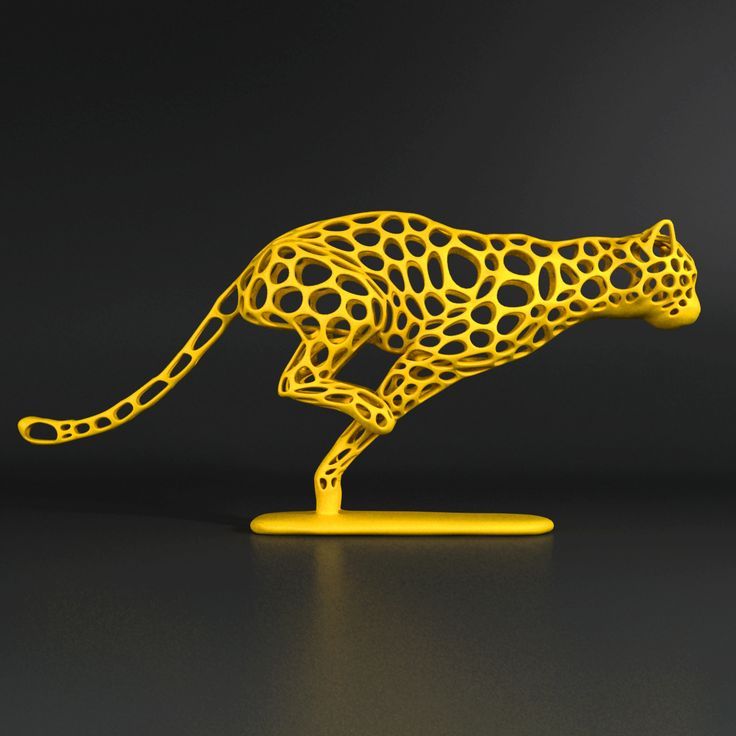 Then use two clamps to secure the hole together.
Ribs
If you're printing a piece that has a protruding feature jutting out from the base, you'll run the risk of that piece breaking, even during the printing process.
To avoid broken 'arms and legs,' add triangle supports or 'ribs' around protruding pieces to support the base. Ribs strengthen fragile protruding features by supporting perpendicular angles. Without additional support around their bases, these structures are more likely to snap off.
Webs
'Webs' are another form of built-in support used to maintain the integrity of shells. They consist of a network of supportive structures and protruding pieces that help a body keep its shape without having to print a solid structure (saving hours, or even days). If you're testing different shapes and ergonomic structures, design webs or infills into your object to speed up the process.
3D Printing With Webs - Solid model of a waterbottle prototype with web support modeled in Shapr3DThreads
The heat naturally occurring during a print increases the difficulty of printing threads by contracting the details and making them unusable for your original purpose. The smaller and more detailed the threads, the more difficult the print
Before printing, add an additional tolerance between 0.5-1 mm to your model to make up for any heat shrink or imperfections. Small blobs on a tight-fitting thread will act like sand in a gearbox, making it impossible to screw the part on.
3D Printing Threads - The thread on the right was printed with a smaller nozzle and layer height — print threads horizontally for the very best resultTo create a better thread, round the crest and roots in the design process — sharp edges tend to concentrate stress.
Alternatively, you can design additional ‘dog point' heads onto your screw. This flat, unthreaded tip helps a successful print and is helpful for locating a groove on a shaft. Ensure the length of a dog point head measures at least 0.8 mm.
Model of a Screw With Dog Point HeadInfill
If designing a large part, save both time and material by considering different infill patterns that use less material.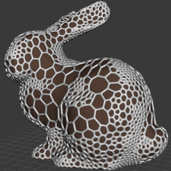 You can manipulate these in your 3D printing slicer. Hollow, geometric shapes characterize infill patterns with the density and shape of the infill affecting the strength of the final printed material.
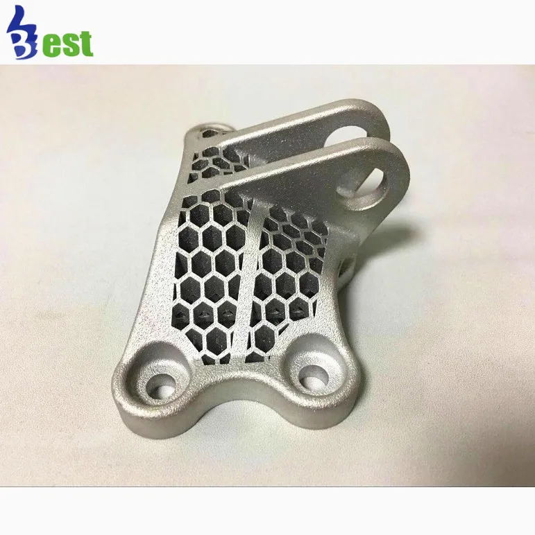
Hexagon or honeycomb infill is the strongest, most efficient infill and also the fastest to print. Honeycomb infills mimic naturally occurring hexagon patterns used throughout nature.
Explore printing a ‘wiggle' infill to give your piece a distinct look. Triangular infills have a high lateral load-bearing capability, making it a good choice for bridges.
Part Orientation
The right part orientation improves the strength, appearance, and print time of your piece. To ensure optimal strength, manufacture in additive layers parallel to the layers of your object.
When designing your piece, consider the load-bearing capacity and direction of the parts, and then orient the part accordingly.
As a rule, orient cylindrical features like columns vertically for a smoother surface finish. Orient holes with faces parallel to the XY plane for a better resolution as well.
Orientating Your 3D Print - Printing horizontally versus printing vertically will have a different effect on both the texture and support design of your objectExporting your STL file
When you're exporting a file for 3D printing, always use the highest setting STL file. STL files are a list of triangles, and cannot store separate bodies. As such, an STL export of touching bodies may merge. Make sure to separate each body where possible.
For graphics, export in medium or experiment with a low setting. You may need to remesh or generate a quad mesh if the mesh isn't uniform. If post-processing is required, export using the highest setting.
It's time to get your hands dirty
There you have it, the top design considerations to cover before 3D printing your prototype.
To prepare for manufacturing your model and save yourself from shaking your fist at gravity, go through and assess these factors one last time:
- Printing nozzle and material for your use case
- Wall thickness and overhang angles and lengths in your 3D model (and how they'll hold up in your 3D object)
- Model orientation
- Build plate adhesion
- Infill patterns
Download Shapr3D
Shapr3D: the First Production-Ready 3D Modeling App - 3DPrint.
 com
comOne of the biggest obstacles to widespread adoption of 3D printing, particularly for consumers, is the steep learning curve associated with CAD software. To work with SOLIDWORKS, the most prolific of the CAD programs, usually requires at least a college degree in mechanical engineering. However, the existing computer design paradigm is on the precipice of a major change.
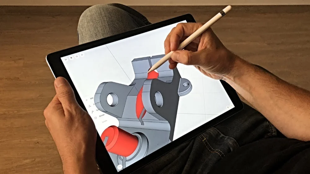
Just as low-cost desktop 3D printers are beginning to democratize manufacturing, new CAD tools are emerging to make 3D design less of an esoteric skill. One of the most prominent examples is that of Shapr3D, a tablet-based software for 3D modeling. Whereas, up until now, the app made it possible to quickly and intuitively draw complex geometries, the company behind it has now introduced new features that set those models up for actual manufacturing.
Founded by CEO István Csanády in Budapest in 2015, Shapr3D has created a remarkably advanced, yet easy-to-use CAD modeler for iPads that relies on the Apple Pencil to draw out geometries using the same Siemens Parasolid engine as SOLIDWORKS and Siemens NX.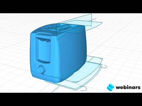 This is no small feat, as advanced CAD requires advanced computing power, making mobile modeling a typically slow and painful task. The software is notably fast when it comes to modeling on the iPad, but the speed with which Shapr3D is developing the software is also surprising. Having achieved an Apple Design award, the company has also signed up 24,000 paying customers in just a few years.
The app works by allowing users to draw a shape with the Apple Pencil and then extrude it to create a 3D model, offering a full modeling toolchain. This can all be performed on existing SOLIDWORKS files, as well. With the ability to export models as STL files, this makes Shapr3D one of the most advanced tablet tools for 3D printing.
Drawings in Shapr3D. Image courtesy of Shapr3D.
Now that it has conquered the task of quick and easy tablet modeling, Shapr3D is taking the next step, a 2D Drawings feature necessary for the actual production of designs. With this tool, users are able to generate drawings from objects, systems, and structures that provide manufacturers with the key information and requirements needed to bring the models into the physical world.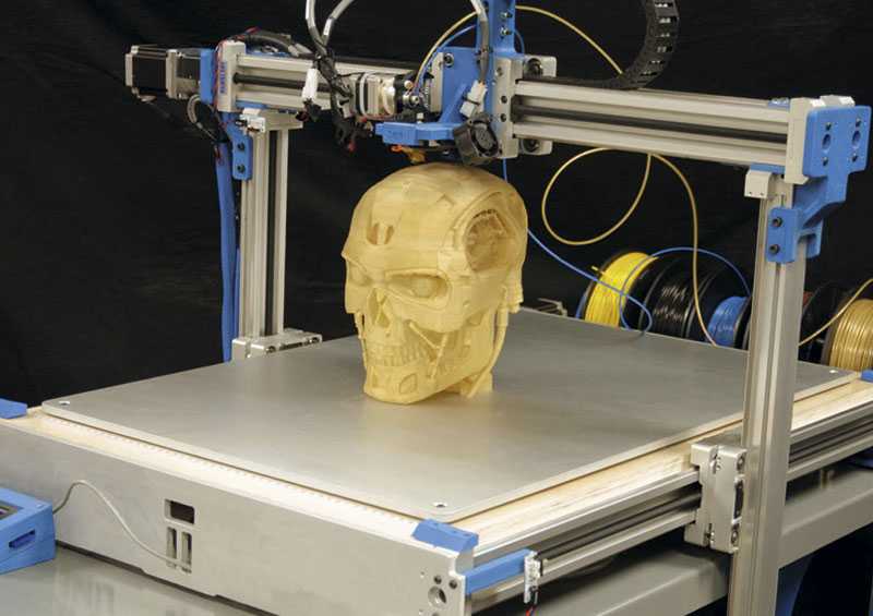
Shapr3D users have been clamoring for this feature as they have been, until now, relying on outside software to generate 2D drawings. Now, they can generate the drawings within the software, meaning that they don’t have to leave the program to create drawings for their manufacturers.
Image courtesy of Shapr3D.
According to the Shapr3D team, some users will already be able to create technical drawings for manufacturing when they get a hold of these new features. At launch, Drawings will include standard base views, dimensions, basic notes, project border and a simple title block. By the end of March, there will be more advanced title block options, as well as section, auxiliary, and detail views, along with advanced notes, centerline and centerpoint features. This means, the number of users that will be able to send their designs to production will only increase as the end of the quarter draws near.
The closest competitors to Shapr3D are Onshape (bought by PTC), Fusion 360, and uMake, all of which have some drawbacks. Onshape and Fusion 360, for instance, seem more like programs that began as computer-based CAD that were then translated to the tablet, with Apple Pencil as more of an afterthought. This makes them significantly less intuitive.
The startup’s CEO, István Csanády, is already well aware of the potential for other mobile applications, such as augmented reality (AR). AR capabilities were released in fall 2020, with users able to see how their designs look in physical space and then capture screenshots. By adding a much-demanded Drawing feature, Shapr3D is setting itself up as the first mobile CAD app that is production-ready. We are no longer living in a desktop computer world and it’s about time that CAD tools start acting like it.
Stay up-to-date on all the latest news from the 3D printing industry and receive information and offers from third party vendors.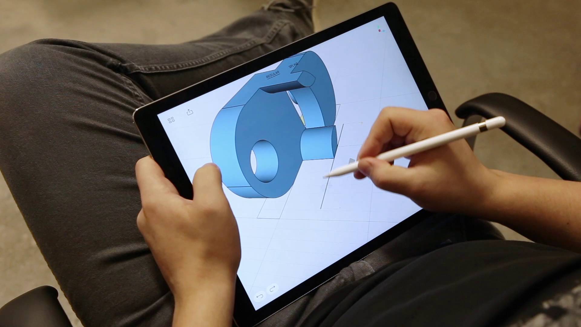
Tagged with: 3D modeling • 3D modeling for ipad • engineering drawings • ipad • Shapr3D
Please enable JavaScript to view the comments powered by Disqus.
how small details make a big difference in the perception and experience of using CAD
Articles about CAD/CAM and CNC
Today we have a review of the coolest iPad CAD product. And, of course, we are not talking about the classic and well-known CAD, but about a very promising development of the Hungarian startup Shapr3D, which not only introduced the world's first native modeling application for iOS and MacOS with the latest Apple M1 processor, but also competently implemented the concept of joint using the touch interface and stylus. This is the case when seemingly insignificant details seriously change the experience of using and perceiving a CAD system. nine0003
I dare say that MacBooks and, to a lesser extent, iPads are often the choice of professionals: programmers, artists, and journalists. As far as CAD/CAM tools are concerned, Apple users have few options, to put it mildly. Macs usually run Parallels and use Windows applications. The App Store on the iPad offers a selection of the already popular Onshape and Fusion 360, which, by the way, did not work well for me, plus a dozen less powerful applications for sketching, designing and viewing CAD files. nine0003
The Pro model of the iPad line brings to the tablet form factor not only powerful computing capabilities comparable to those of desktops, but also equipped with several useful hardware options: the Apple Pencil stylus, a full Magic Keyboard with touchpad and lidar to implement various AR scenarios.
In general, this is a really cool device and, probably, it would be a sin not to use its potential for 3D modeling tasks. Apparently, the founders of Shapr3D reasoned in the same vein, who rightly assessed the prospects for a free niche in the iOS marketplace, and decided to create a professional mobile CAD system that would make full use of the iPad concept, controls and interface. Let's see what the software product is today and what results has Shapr3D achieved since its launch in 2016? nine0003
First of all, after downloading and installing the application, the user is invited to take a short training course. We can definitely praise the developers here, since there are few introductory lessons, they are interactive and allow you to literally master the basic methods of working in the system in just a couple of minutes, realize the convenience and comfort when working synchronously with your fingers - to navigate and control the view, and with a pencil - to select operations, create and editing geometric elements. Moreover, these basic lessons, as well as the entire Shapr3D interface, are translated into Russian with high quality. nine0003
But there are a couple of disadvantages: firstly, I did not find the opportunity to skip the introductory lessons, and you will have to go through them again, even if you already know how to work in the system (for example, in case of reinstalling the application), and, secondly, when choose more detailed reference materials in the application, you are simply transferred to YouTube videos with examples, and only in English.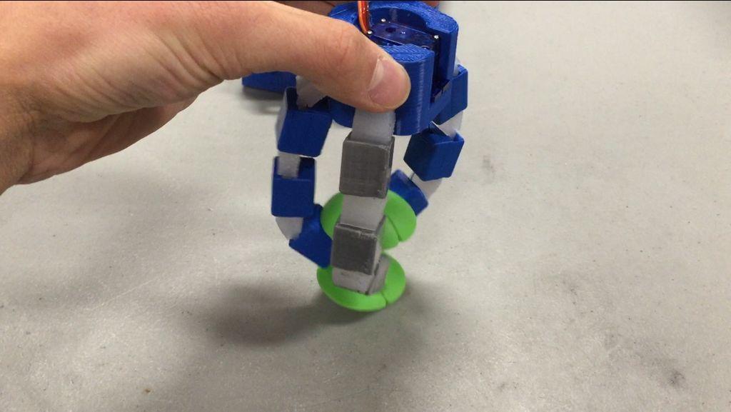
After successfully passing the introductory part, it becomes possible to create a project. Shapr3D offers only two licensing options. You can buy a subscription - it costs $25 a month, or if you pay upfront for a full year, $20 a month, so you can save a fifth of the cost. Or stay in the free version, of course, with a number of limitations, the most significant of which is the inability to start more than two projects, use colors and export the created geometry to popular CAD formats. nine0003
The good news is that a free trial period of the full version is available to the user, and there are two whole weeks for a thorough study and testing of the product. Plus, the free "Basic" version does not limit functionality in CAD - absolutely all tools for sketching and 3D models remain open.
Technical side of the issue: Shapr3D is built on the Parasolid core and can be classified as a direct modeling system. The application has a wide range of tools that will help you build geometry from scratch based on sketches and 3D elements, as well as modify existing or imported geometry by extruding, rotating and other standard operations. As for import, Shapr3D is able to open Parasolid (X_t, X_b), SolidWorks (SLDPRT, SLDASM), STEP, IGES, DXF, DWG, JPG, PNG formats. nine0003
There are four main toolbars for operations and commands. By default, they can be found on the left side of the screen. To create sketches, you have a complete set: from lines, circles and arcs to ellipses and polygons, as well as modifiers such as offset and cropping. There are two options for creating a spline: control points and fitting.
In addition to sketching entities, constraints are also available, including tangency, perpendicularity, concentricity, parallelism, symmetry, and so on. They can be applied on the fly or after the fact. nine0003
There is one thing that is hard to get used to after your experience with classic desktop CAD systems, and that is the sizing workflow for sketches. Instead of requiring formal dimensions, Shapr3D works with selections and displays possible dimensions: click on a line, get the length dimension; select two lines, get distance or angle size and so on.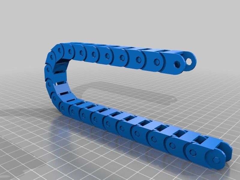 If you formalize and set the values, then they will be preserved during any subsequent changes to this sketch. nine0003
The "Tools" panel is the most important, it has all the classics of 3D modeling: extrusion, rotation, unfolding, loft and shell. There are also a number of boolean operations: union, subtraction, intersection, as well as commands for geometry projection, edge offset, and face replacement.
The Add panel provides auxiliary geometry: planes and axes, as well as the ability to import geometry from the iPad file system. The section will also allow you to use the images as a reference, and given Shapr3D's usefulness for concept development, this definitely makes sense. nine0003
The Transform panel contains the familiar functionality for moving, scaling, mirroring, and aligning geometric elements. Of course, there are commands to rollback actions back and forth.
As for the possibilities of direct modeling, I did not find anything unusual or revolutionary here.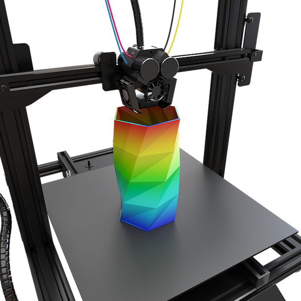 If you have a face that you want to shorten or extend in a solid model, you can select it and a small arrow icon will appear to indicate the direction of change. Drag it into the part and it will cut out the geometry. Drag it away from the part and the face will be extended. Here you can also specify the exact size in the box. If you need a more complex transformation, for example, with the addition of a slope, use the extrude command - the sign of the slope angle will appear on the screen. nine0003
Nicely implemented color management, transparency, saturation and luminosity. Three sliders and a color palette with an eyedropper make it quick and easy to color a 3D model.
When it comes to focusing on a specific task, double-tapping an edge with your finger switches the image to that edge, it turns towards you. Clicking with the pencil selects it and offers a move operation. If you double-tap with the pencil, the entire body will be selected. Most of these gestures and interactions are intuitive and easy to get used to.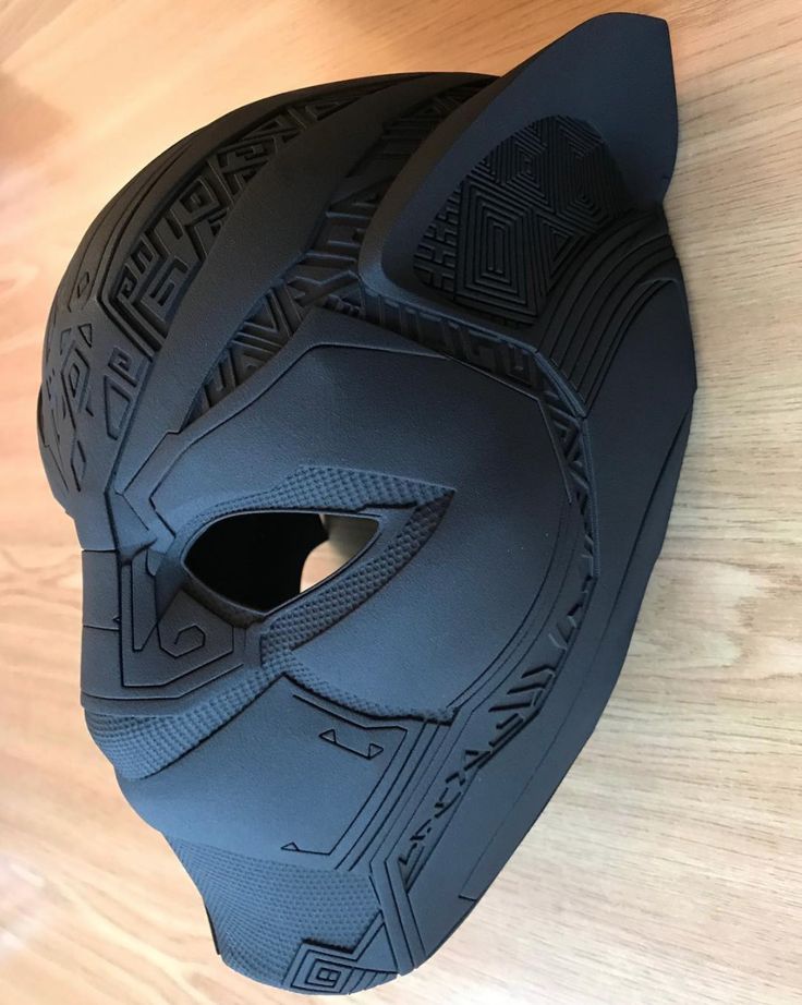 nine0003
While Shapr3D doesn't formally have the assembly modeling tools that come standard with full-blown design systems, there's enough power here to let you create and manage a more complex set of parts in a single file.
Obviously, this can be done at the solid level, but if you open the "Objects" manager dialog, you will see a list of solids, planes and sketches. They are given default names that you can easily rename by swiping the entry to the left. This window also allows you to group bodies into folders that act as subassemblies. nine0003
So how do you get data from Shapr3D? This is perhaps the most surprising part given the nature of the system. In the “Pro” version, you can export your data as high quality Parasolid (X_t or X_b), STEP, IGES, OBJ and STL files. In addition, the "Export" section offers the preparation of a three-dimensional model for a 3D printer, saving project sketches in DWG and DXF formats, creating screenshots and removing user interface elements, which will be useful for sharing with a colleague or including graphics in a presentation.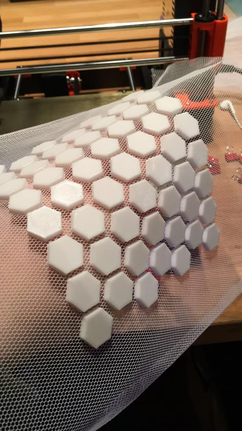 nine0003
The “trick” of the system is impressive - the ability to place a 3D model in a certain environment using augmented reality technology. For example, place the created object on the table or the floor of the room. Here, there is a special hope for Apple that they will nevertheless present some kind of breakthrough consumer AR solution that will justify the presence of such functionality in the software and the actual lidar itself in the iPad Pro.
Well, let's summarize. It is encouraging that the Shapr3D team is taking a different approach than its competitors and predecessors. The focus on combining finger interaction with the precise input offered by the Apple Pencil makes sense and transforms the perception and experience of using a CAD system. At the same time, the system accurately feels the difference when touched with a finger and a pencil, and performs the corresponding actions. The interface is beautiful, modern, pleasant to look at, and easy to interact with. nine0003
But still, I would consider Shapr3D as a tool for conceptualization and 3D thinking, and not as a full-featured 3D design system. Instead, just sketch 2D sketches, experiment with 3D models, see what you get. If you already have an iPad, then Shapr3D will allow you to view CAD files, for example from email, with robust Parasolid-based tools, and potentially edit them very quickly. You may even be able to prepare good models for 3D printing, but definitely not launch into some serious production. At least at the moment. nine0003
Judging by the publications on the site https://www.shapr3d.com, the project has gained a decent audience of 20 thousand users with iPad Pro, raised multimillion-dollar investments, and is definitely not going to stop there. A beta version for MacOS is already available, and with full support for the Apple M1 processor - which means that “everything will fly”, the ability to connect a keyboard and mouse is announced. Not bad.
And here I have a question, or rather an idea - isn't it time for such Russian talents as ASCON and TOP Systems, with their experience and resources, to go ahead, play in this new promising and as yet unoccupied field of the Apple ecosystem ? After all, there is a Parallels success story. nine0003
Read also:
- "This is what serves as our pivot!" – Big interview with Maxim Bogdanov and Alexander Golikov
- WinTool: our strength lies in integration
- New Era of Shared Future
- ESPRIT: our strength lies in new technologies
- Olympic CAM-system. Report from ESPRIT World Conference 2015
- Visiting CIMCO
- Big little trip to 3DEXPERIENCE WORLD 2020
- VERICUT: our strength lies in high precision
- Mastercam: Our Reseller Network Strength
- PLM Market Intelligence Business: Interview with Peter Bilello, CIMdata President & CEO
Comments (0)
Leave a comment
Log in or Register to leave a comment.
Home repair with a 3D printer
Hello, my dear friends!
Today I decided to show how useful and necessary a 3D printer can be when renovating a house. I'm not talking about some kind of global renovation of the entire apartment, but I mean the repair of some specific things at home. nine0003
As you know, all futurists and other smart guys foretell that 3D printers should be in every home, but not everyone understands why he needs a 3D printer at home and what he can do with it.
And today's example will be one of many hundreds of thousands of millions of ways to use a 3D printer at home.
Let's go!
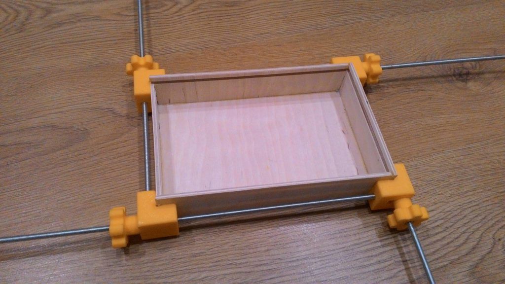
So, to begin with, we must have a problem.
The problem is that I have things lying on the floor right now. And this happened due to the fact that in the dressing room in our rented apartment the fastenings of the crossbar holders broke. The owner of the apartment did not get too confused so that everything was secure and therefore the fasteners were additionally fixed with adhesive tape. Accordingly, at one point the crossbars fell! nine0003
What could be done in such a situation: wrap more adhesive tape and electrical tape, drill some additional hole, somehow screw it tighter... But! When you have a 3D printer at home, you can make a piece that never existed in this beautiful world and improve this closet system so that the bar will never fall again.
We are moving on to the next step - Solving the problem.
How to solve the problem?
It is necessary to come up with a part that will be attached to the rack and on which the crossbar will be fixed.
To do this, I will use my little engineering brain. First you need to figure out how the part for attaching the rail should look like. in my head. And then use a little artistic talent. I'll take a tablet, take an apple pencil and try to sketch how this part will look like. I got such an interesting sketch, where there is a part that is attached to the rack and a crossbar is inserted into it. Actually, the part itself is not particularly complicated. nine0003
Now I move on to the next stage - Design.
First, I take all the necessary measurements. In this case, this is a rack, its various cavities and the dimensions of the crossbar itself.
I used the Shapr3D application for the design. I already talked about this application in the video "3D modeling on iPad | Cooler than on PC? | Onshape, Fusion 360, SolidWorks, Shapr3D". You can follow the link and watch it.
Using Shapr3D, I roughly modeled the part that I considered the very savior of our dressing room. nine0003
And to make sure it would fit, that all the dimensions I was looking for, I printed a test sample of our Clotho ABS glass fiber composite in natural color, which, by the way, will not be sold at first. But if you think that glass-filled material in natural color should be, write about it in the comments. I used this material for the prototype, but also the final parts and I also want to print from this material, because this glass-filled composite has a 34% higher interlayer adhesion than regular ABS plastic. The higher the interlayer adhesion, the stronger the part and it can be used for printing highly loaded parts. nine0003
And then the question arises of how to properly position such a part for 3D printing.
When we design, we need to understand how the load will be placed in order to understand how the part will then be printed.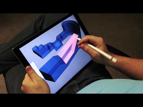
In this case, I had two options for printing this part.
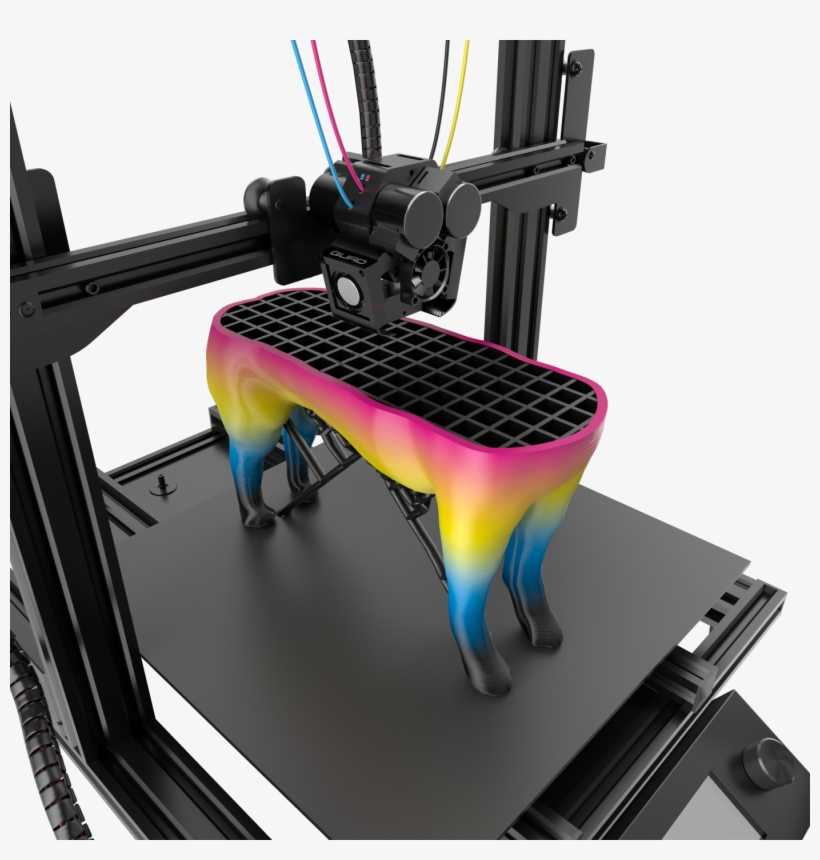
In the first variant, the layers are arranged parallel to the load, and in the second variant, perpendicular to the load.
Taking into account how the forces will act, I chose the option of arranging the layers perpendicular to the load. Write in the comments how you think the item should be placed. nine0003
And go to the step - Test Print.
I'm preparing the model in our Diaprint software, which can also be used on a tablet without any problems. I choose a finished profile for Clotho ABS. I just made some minor adjustments to my profile. Namely, I reduced the speed to 65 mm / sec, because the part has an inclined part. With such dimensions and high speed, the material will not have time to cool down, the edges of the part will bend and there will be a not very beautiful angle. By reducing the speed, no corner was bent and everything turned out smoothly and beautifully. nine0003
Next, I checked all the dimensions for compliance with the specified ones.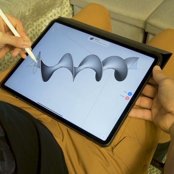 All dimensions correspond, but I decided to add something to the part itself and improve it a little: add fillets, increase the hole for the bolt head.
Having finalized the part, we start a series of 4 pieces.
25% coverage, 0.5mm nozzle, 0.25mm layer, 65mm/sec print speed, added some cooling.
No need to be shocked that I added cooling on such material. In fact, we are blowing warm air, because. the chamber is closed and the air is heated in one way or another, and this makes it possible to eliminate the bending of corners. I note that on the Hercules G2, the airflow of the model is turned on separately from the airflow of the entire chamber. This is done just so that when printing with various materials, various parts can be separately controlled by blowing in the chamber and blowing the part itself. nine0003
Once again I checked the finished 4 parts for compliance with the dimensions and went to install.
I drilled a few holes in the rack, screwed the printed part on, put in the rod and you're done.