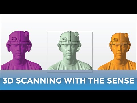
Sense 3d scanner tutorial
3D SYSTEMS SENSE USER MANUAL Pdf Download
Download Table of ContentsAdd to my manuals
Bookmark this page Manual will be automatically added to "My Manuals" Print this pageTable Of Contents
3-
page of 18
- Contents
- Table of Contents
- Bookmarks
Advertisement
Table of Contents
Copyright Notice
Table of Contents
Introduction
Safety and Compliance
Sense Scanner Setup
What's Included
- Download the Sense Software
Install the Sense Software
Run the Sense Software
Activate Your Sense Scanner
How to Scan
Sense Navigation
Scanning Best Practices
Scanning Procedure
Edit a Scan
Sense Scanner Tips and Tricks
Sense Settings
Scan Settings
Edit and Enhance Settings
Export Settings
Features and Specifications
Sense™
3D Scanner
User Guide
Table of Contents
Previous Page
Next Page
Table of Contents
Related Manuals for 3D Systems Sense
- Scanner 3D Systems Geomagic Capture Series User Manual
Harness the power of 3d scanning (25 pages)
- Scanner 3D Systems iSense User Manual
3d scanner (14 pages)
Summary of Contents for 3D Systems Sense
Eickhoff Design
Individual Assignments:
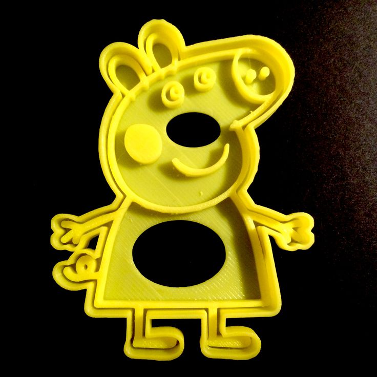
1. Design and 3d print a part which would be impossible (read: very difficult) to make using another fabrication technique.
2. Use a 3D scanner to generate a mesh/3D graphic.
Group Assignment:
Characterize our lab's 3D printer with a test part
Process
For the past year or so, I've had a dream to hold a 3d printed model of my heart in my hand. I have a set of CT scans that were taken of my heart a few years ago, and tried my hand at doing something with those images months ago, but the boundary between regions of the heart and the surrounding tissues was difficult to draw and I ended up putting the project on the shelf. This week's assignment seemed like the perfect impetus to dust it off.
First thing's first: the CT scan is stored in a stack/series of 2D images, referred to as DICOM files. I found an open source program called3D Slicerwhich was developed specifically for visualization and medical image computing. From the welcome tutorial: "Slicer is an open-source software for segmentation, registration, and visualization of medical imaging data. " Sounds promising...
Even more reassuring to an inexperienced user like myself, there is awikiwith training materials available to anyone interested.
However, despite the many hours I spent trying to clean up the data, this week was quite frustrating in that I have little to show for my efforts.
Phase I: Research
I spent many hours pouring over resources online, looking at what other people did so I could follow a similar workflow. One challenge with this is that the 3D Slicer software is being constantly updated- there are new features being released all the time as this is an active research area. Some of these new features can lead to major time savings, but it's hard for the tutorials to keep pace with the progress and I ran into some outdated tutorials which showed the old way of doing things. It was a balance between following in the steps of others but also knowing when to deviate in order to take advantage of the latest features. Slicer is a massive piece of software. It's built in terms of modules. One extremely valuable tutorial wasthis one, created and distributed by Slicer itself. This tutorial is the holy grail for understanding basic navigation and layout of Slicer. Hallelujah!!
Phase II: Load Data
Ok, now that I'm oriented...time to load my data. The simplest way to load a DICOM directory into Slicer is just drag and drop. The DICOM Browser module opens up and you can select which of the data you want to load.
DICOM Browser.
And after clicking 'Load', suddenly my images fill the screen. I called my fellow Fabbers over to check it out.
That's me!!
After playing with the slices a bit more, scrolling through the images in wonder and awe at getting to see a view of myself that many never would, I was ready for the next step.
Phase III: Crop to Region of Interest (ROI)
My handy tutorial now instructs me to open the Volume Rendering module.
Defining the Region of Interest to crop the volume to.
Phase IV: Segmenting
Slicer has a really cool 'seed and grow' feature for assigning different parts of an object to regions. You start by planting 'seeds,' each different color representing a different tissue type/piece of anatomy. Once you've marked each tissue type you want mapped, the software will automatically start 'growing' the seeds so that all pixels in your ROI are assigned to a segment.
Drawing in the 'seeds': each color represents a different region of the heart.
After the program has 'grown' the seeds, you can clean up the boundaries between the regions by drawing in the appropriate color.
As you can see, I've segmented the volumes of the chambers and vessels of the heart. I'm hiding the 'Other' region (which consists of the cardiac muscle as well as the air surrounding the heart.
Unfortunately, as my tendency towards perfectionism peeked in and I spent longer trying to perfect the segment regions, I found that I reached a point where I'd over defined a boundary and it was going further into another segment than I wanted it to. It was at this point that I realized, to my dismay, that the undo button wasn't working.
I've gone too far...and I can't go back?!
Scanning
I hadn't used a scanner before, but knew I wanted to try scanning something that would be difficult to model if I were just starting off from scratch. The strength/advantage of scanning comes from taking an object in reality and getting it into a virtual environment where it can be manipulated. Scanning something like a waterbottle, which would be relatively easy to create just by measuring and modeling the geometries, doesn't make a lot of sense.
I tried using 2 different scanners available in the lab: 3D System's 3D Sense, and Creaform's HandySCAN.
Attempt 1: Bike with 3D Sense
At first, since I was interested in doing something bike-related for my final project, I thought I'd try to scan my bike (which I'd ridden to the lab that morning).
Setting up the bike for scanning.
However, the scanner had other ideas about what it wanted to capture. I was using the 3D Sense handheld scanner.
Bike scan...not accomplished
Attempt 2A: Walnut with 3D Sense
Since the bike scan was not very successful, I pivoted and decided to try scanning an irregular, organic object- a walnut.
The first attempts with the handheld scanner yielded very disappointing results- I later realized while doing some more research that the small size of a walnut, or anything of that scale, makes it a challenge to scan.
Since I wasn't getting anywhere with the handheld scanner, I decided it was high time to try my luck with the fancier scanning system that a few of my other classmates had moved on to.
Attempt 2B: Walnut with the HandySCAN 3D
CalibrationMoving over to the other system, the first step was calibrating the scanner.
Calibration within the scanner's case.
Software interface showing calibration.
The whole calibration system, including Your's Truly.
Pilar and I each tried calibrating the system- it was not trivial to do so! The task required a fair about of hand-eye coordination and the ability to keep the scanner level while moving it around the grid of tracking dots. The interface gave a lot of feedback along the way.
This scanner works by using a series of markers (and how they relate to each other) to track surfaces
Walnut set up pre-scan.
HandySCAN scanner with walnut and markers in the background
ScanningTime to scan!
There is some skill involved with scanning- you want your movements to be as smooth and constant as possible, and stay equidistant from the object. This scanner does give you valuable feedback if you're too close or far from the object in the form of different colored lights and a message on the computer screen.
Very concentrated work.
Resulting scan.
The scan with the HandySCAN system came out much better than the 3D Sense had; the scanner was able to register that there was a walnut there. I did notice some limitations of the resulting scan, however: it was difficult to get the bottom of the walnut, where it was resting on the table. In addition, the scanner also scanned parts of the table itself, which would need to be removed if I were to try to 3D print the object.
I experimented with adding another scan to the previous one, and found myself with the entertaining image below. I'm sure there's a way to register the two scans via software, aligning the images, but I didn't have time to explore that functionality.
Oops.
Design & 3D print
Designing a 3D object
First, I designed a 3D object in Autodesk's Fusion 360. I wanted my object to be difficult/impossible to manufacture using traditional (non-additive) manufacturing techniques.
The object in Fusion 360.
Preview of the STL (mesh) to be exported from Fusion 360.
Butting Heads with Meshmixer
Next, I was determined to incorporate a voronoi pattern into my structure- this would add an organic element and truly leverage 3D printing to create.
To do so, I tried to follow a tutorial which my classmates found, which uses a program called Meshmixer. From the website, Meshmixer looks like an impressive piece of software with many capabilites to help clean up and modify 3D meshes. Perfect for applying a voronoi pattern.
Sounds great! Let's jump in, shall we?
Not so fast.
For whatever reason, and despite many uninstall and reinstall attempts, I could not get Meshmixer to function (or even open) on my computer. Having spent many hours troubleshooting, I moved on to another mesh editting program, MeshLab.
Editing the mesh with Meshlab
Mesh freshly imported into Meshlab.
I then proceeded to follow instructions on a tutorial for how to apply a voronoi pattern to my mesh.
Navigation for resampling to generate a uniform mesh.
Object after uniform mesh applied.
Applying Poisson-disk sampling.
Preparing to apply Voronoi coloring.
Applying Voronoi coloring.
Return to Meshmixer
Turns out, Meshmixer really is the tool I needed to get the look I wanted. Reaching the end of my patience, my classmate Pilar, who'd already gone through the process, walked me through how to apply the Voronoi pattern on a different computer which had Meshmixer running successfully.
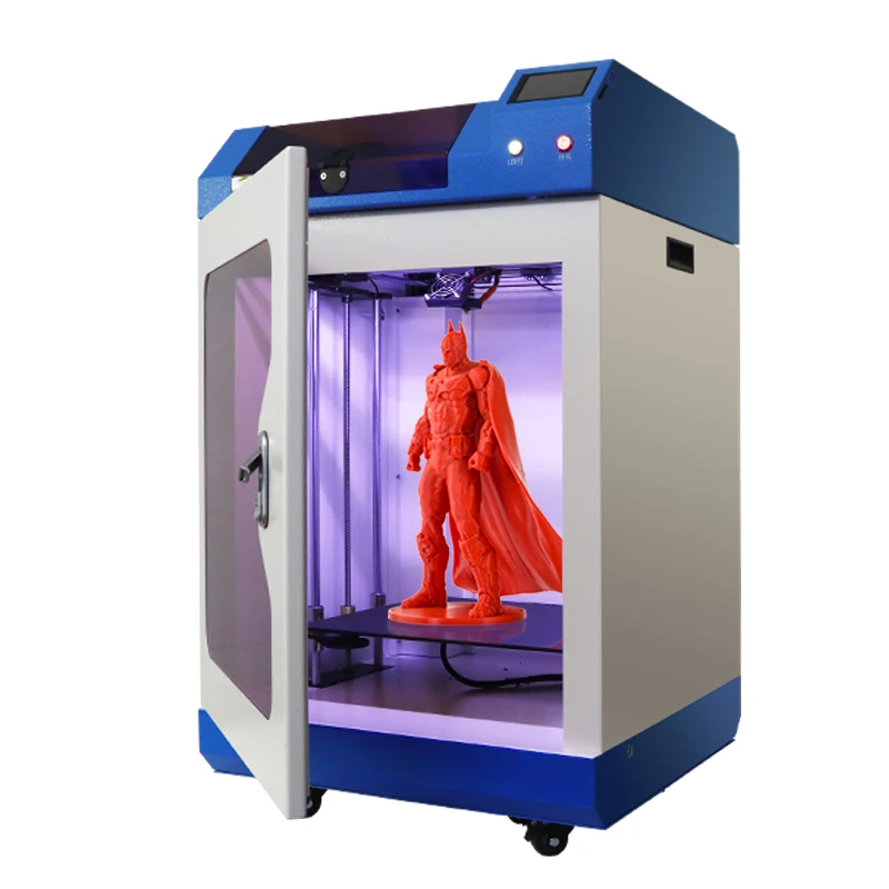
3D Printing
I was intent on using the 3DWox printer by Sindoh since I'd never used it before and Neil sang its praises during class as one of the most reliable 3D printers. We have quite a few here at the 3D Experience lab at Dassault Systemes, but at the time when I was trying to print, several of the fleet were out of commission. It took a few tries before I found a printer which was functional and available.
I used the Sindoh software to load my STL mesh and generate G.code for the printer to read. From there, I transferred the G.code to the printer via thumb drive and at long last, my mesh was printing out as a physical object.
At last! 3D print is underway.
Final result of my 3D print
School use of 3D scanner SENSE
Instructions for scanning an object 3 D scanner SENSE
1 . Connect your SENSE 3D scanner to a PC using any available USB port.
2 . Launch the SENSE scanner software on your PC. (Start - All Programs - Sense - Sense.exe)
3 . In the Sense dialog box that opens, select the type of object that you are going to scan with the scanner. For example, "Man".
4 . In the selected section, select the desired subsection of objects. In the "Human" section, you can select two subsections "Head" or "Whole body". In the "Object" section, you can select three subsections: "Small object" (from 20 cm to 40 cm), "Medium-sized object" (from 40 cm to 1 m.) and "Large object" (from 1 to 2 m.).
Section "Object" and its subsections:
Section "Person" and its subsections:
5 . In the previously selected "Person" section, click on the "Head" subsection.
6 . In the dialog box that appears, find the black circle in the middle, which is the target when scanning the object. During the entire scanning process, it is necessary that this circle is always in the middle of the scanned object. The main control elements are located in the upper right window of the program: Home / Exit / Scan settings / Help. At the bottom in the middle is the "Start Scan" button
7 . Before scanning, go to the scanner settings by entering the "Scanner Settings" section. We check and set the necessary settings, as shown in the figure below for the "Head" subsection
8 . After that, we take the SENSE 3D scanner in our right hand, direct the black circle to the center of the scanned object and press the "Start Scan" button. The distance to the scanned object should be about 35-40 cm, the scanning angle should be about 60-70 degrees. After clicking on the “Start Scan” button, you will have 3 seconds to prepare, after which the scanning process will automatically begin.
9 . Smoothly, with uniform acceleration at an angle of 60-70 degrees and a distance to the scanned object of 35-40 cm, the process of scanning the object from all sides (360 degrees) begins. See how the scanner moves around the object.
10 . After passing the 3D SENSE scanner around the object, press the button at the bottom of the Stop Scan dialog box. On the PC screen, automatic construction of a 3-dimensional model of the object will begin.
11. A “raw” 3D model of the object will appear in the program dialog box, which can be viewed in different planes. To do this, while holding the left mouse button, move the mouse in the direction of any of the planes (X, Y, Z)
12 . The next step is to process the created "raw" model. Click the "Next" button in the lower right corner.
13. Select the Crop tool at the bottom of the dialog box, after which, holding the left mouse button, we select the area around our created 3-dimensional object, as if cutting off the excess around it.
14 . Select the “Erase” tool and, holding the left mouse button, paint over with red the extra edges and objects that could not be removed after cropping.
15. After “Cropping” and “Erasing”, click on the “Approve” button. After that, the program automatically refines your received 3-dimensional object. She finishes the gaps and shortcomings that turned out during a normal scan. It turns out a better volumetric model.
16 . Click the button at the bottom of the Next dialog box. The Enhance dialog box opens. Here you can change the color/contrast of the model, retouch imperfections, scan inaccuracies and truncate (crop along any of the X, Y, Z planes). Here we leave everything unchanged for our example.
17. Click the "Next" button in the lower right corner of the dialog box. A window will open where you can save our received 3D object, print it on a 3D printer (provided that the printer is connected to the same PC and configured), send it to the cloud (to a remote storage on the Internet). Press the "Save" button. In the dialog box that opens, set the file name:
Proper scanning procedure involves moving the Artec 3D Scanner around the entire object. The system starts the process of leveling the scanned surface in real time, which allows you to start scanning accurately and correctly and determine the required amount of work. In this case, the user can perform scanning in any convenient sequence.
The user can perform any desired number of scans to ensure complete capture of the scanned object.
 If necessary, you can first scan one side of the object, then stop scanning with the Stop button, and then rotate the object to complete the scan.
 To obtain a single model, the system must align all scanned images, and if the survey is not completed to the end, then you can repeat the scanning procedure for the desired area.
A complete 3D model can only be obtained after all scans have been merged. To do this, the hardware software has a special combination algorithm that allows you to do everything in a few seconds.
The scanner has capabilities for mesh optimization, surface smoothing and cavity filling.
Using proprietary software, you can automatically apply a texture to an object in a short time.
The equipment allows you to export scan results to the most common 3D formats: ASCII, AOP, STL, PLY, VRML, OBJ.