Renishaw 3d scanner
Scanning probes
Scanning probes Skip navigationScanning probes can acquire several hundred surface points each second, enabling measurement of form as well as size and position.
Scanning probes can also be used to acquire discrete points in a similar way to touch-trigger probes.
A range of solutions is available, suitable for all sizes and configurations of CMM.
SP25M
25 mm diameter scanning probe with scanning and touch-trigger modules
SP600
High-performance inspection, digitising and profile scanning
SP80
Quill-mounted scanning probe providing class-leading performance with long styli
Scanning explained
Scanning provides a fast way to capture form and profile data from prismatic or complex components.
While touch-trigger probes gather discrete points on the surface, scanning systems acquire vast quantities of surface data, providing a clearer picture of the form and shape of the workpiece. Scanning is therefore ideal for measurement applications where the form of a feature is a significant element of the overall error budget, or where complex surfaces must be inspected.
Scanning requires a fundamentally different approach to sensor design, machine control and data analysis.
Renishaw scanning probes feature innovative, lightweight passive mechanisms (no motors or locking mechanisms) that exhibit a high natural frequency, making them suitable for high speed scanning. Isolated optical metrology systems measure the deflection of the stylus directly (not via stacked axes within the probe mechanism) for better accuracy and faster dynamic response.
How does a scanning system capture and analyse surface data?
Scanning probes provide a continuous deflection output that can be combined with the machine position to derive the location of the surface. When scanning, the probe stylus tip is brought into contact with the feature and then moved along the surface, gathering data as it moves. Throughout the measurement, it is necessary to keep the deflection of the probe stylus within the measurement range of the probe.
For best results, this demands close integration of the sensor and machine control, as well as sophisticated filtering algorithms to convert the resultant data into useable surface information.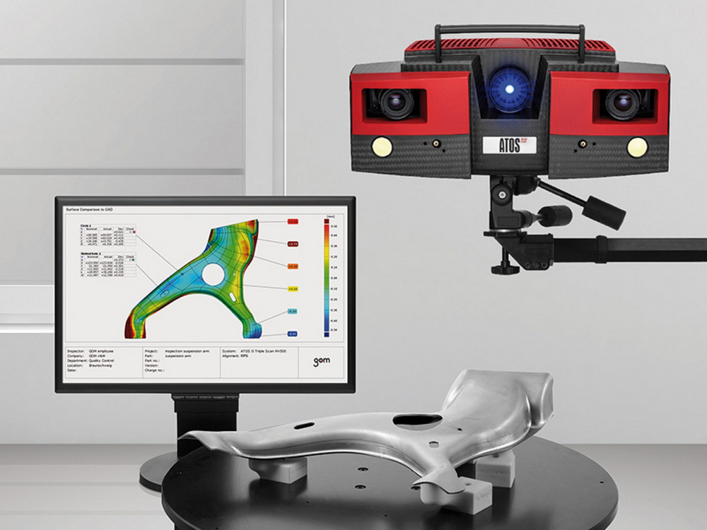 Scanning drive algorithms can adapt to the contours of the part, changing the scanning speed to suit the rate of curvature (going faster on flatter surfaces) and adjusting the rate of data capture (taking more data where the surface changes quickly).
You may also be interested in...
You are currently looking at our scanning systems. You may also be interested to learn about the REVO 5-axis scanning system…
3-axis systems
- Touch-trigger probes
- Scanning probes
- Motorised / automated heads
CMM probes, software and retrofits
- Hardware
- Software
- Retrofit
- Support and downloads
- 5-axis technology
Productivity+™ Scanning Suite
Productivity+™ Scanning Suite Skip navigationAdvanced 3D scanning for industry-changing manufacturing processes.
True 3D – measure complex 3D surfaces at high speed
Accuracy – absolute XYZ surface data with 1000 points per second
Capability – analysis tools optimised for industrial applications
The Productivity+™ Scanning Suite is an integrated on-machine scanning measurement system that records absolute XYZ surface position data with exceptional accuracy.
The Suite comprises a variety of optional application-specific toolkits, each focused on an individual task or industry sector.
Inspect complex 2D and 3D forms
Reduce scrap, enhance productivity and increase profits – the Productivity+™ Scanning Suite can keep complex machining processes under control.
Contact us
Fast and accurate scanning of free-form surfaces
Probe six times faster
Measure up-to six times faster than touch-trigger systems at speeds as high as 15000 mm/minute. Reduce probing time to increase profitable, productive machining time.
Integrated for accuracy
Obtaining real-time machine position from the CNC ensures that high-speed, high-accuracy measurement is not limited by the machine tool path following capability.
Detect feature form issues
On-machine scanning using the OSP60 probe can detect defects in feature form that could be missed by touch-trigger systems.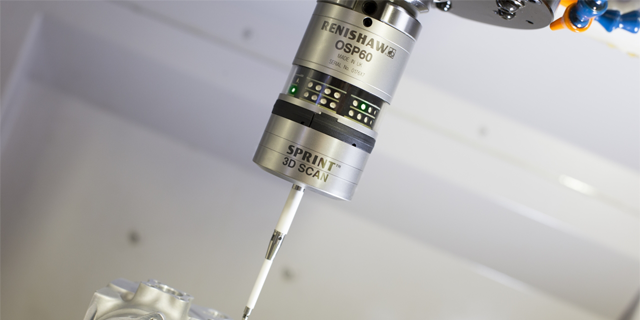
Control your processes
Use measurement results obtained by the OSP60 probe to control downstream machining processes. Real-time results can be displayed on machine or via Productivity+ CNC plug-in software, providing instant feedback and process confidence. Results can also be exported to a file for further analysis.
Prismatic scanning as standard
As standard, the Productivity+ Scanning Suite can accurately measure circles, lines, arcs and planes. These prismatic features are measured on known parts and the results used for part setting or for post-process inspection.
Find out more
Game-changing applications
The Productivity+ Scanning Suite incorporates ground-breaking technology which allows organisations to completely re-think the use of on-machine process control measurement in high value CNC manufacturing tasks. Working in conjunction with manufacturing organisations in key industries, Renishaw continues to develop specific application capability to improve manufacturing processes.
Based on this experience, the Productivity+ Scanning Suite comprises a variety of optional application-specific toolkit packages, each focused on an individual task or industry sector.
Productivity+ Freeform Surface Toolkit
Free-form 3D geometry can be measured at high speed using the Productivity+ Freeform Surface Toolkit; enabling the rapid inspection of complex surfaces with single and double curvature.
Absolute XYZ surface positional data can be reported from free-form surfaces and results can be output to a file for further analysis or stored in machine variables for process control.
Productivity+ Blade Toolkit
The Productivity+ Blade Toolkit offers high-speed, accurate measurement, with exceptional definition of high-curvature surfaces, such as leading and trailing edges.
The toolkit offers a drop-in replacement for an existing touch-trigger process; allowing for easy adoption of scanning technology.
Productivity+ Adaptive Cut Toolkit
The Productivity+ Adaptive Cut Toolkit can rapidly scan the true form of a part, automatically generate a new cutting toolpath that matches the real shape, and instantly upload it to the machine.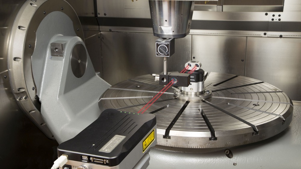
Productivity+ 3D Feature Toolkit
The Productivity+ 3D Feature toolkit allows the user to program arbitrary paths (including broken section scans) on certain 3D features and fit a nominal surface to the data. The user can then report on these features using the standard Productivity+ reporting. This toolkit offers a flexible scanning strategy for parts with interrupted or incomplete features.
Supports 3D features such as circles, cones, spheres and cylinders.
Find out more
Customised applications
Productivity+ MTM cycle
The Productivity+ MTM cycle offers exceptionally repeatable diameter measurement to machine tool builders who produce Y-axis multi-task machine tools for use in the machining of highly accurate diameters.
The cycle provides users with the potential for extremely accurate automatic 'cut-measure-cut' operations with tolerances of a few microns.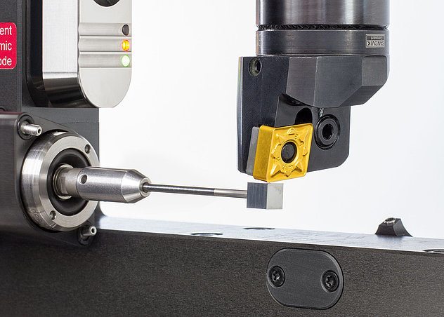
Productivity+ Machine Health Check
The Productivity+ Machine Health Check application provides automated machine tool performance verification in under a minute, helping to prevent scrap due to poor machine conditions. The rapid go/no-go check can monitor machine capability and stop the process to allow more detailed investigation of poor performance to be carried out.
System components
OSP60 inspection probe
An analogue scanning probe for machine tools, capable of scanning and touch measurements.
OMM-S receiver
An optical receiver specific to the OSP60 inspection probe.
OSI-S interface
An optical interface providing input/output communication with the machine tool.
DPU-2 data processing unit
Processes and stores scanned measurement data. Saves results into machine variables (via the CNC API) for use in downstream processes.
Productivity+ CNC plug‑in
On-machine software for generating, editing and running probe routines, using easy‑to‑understand screens instead of complex NC codes.
Productivity+ Active Editor Pro
Simple-to-use graphical programming software that uses solid model geometry to generate the NC code that drives the inspection program.
Next steps
Contact us if you think the Productivity+ Scanning Suite is right for you.
Find out moreContact us
Machine tool products
Inspection probes
Tool setting and broken tool detection probes
Software
Machine tool diagnostics
The SPRINT™ contact scanning system
The Primo™ system
Position and motion control
Machine tool links
- Machine tool products
- Improve your manufacturing process
- Which product would suit your machine shop?
- Support for Hardware and Software
- Probing benefits calculator
- Machine tool custom solutions
Modern methods of 3D measurements, reverse engineering and geometry control
Reverse engineering
Experts recommend
Author: Aleksey Chekhovich
Author: Aleksey Chekhovich
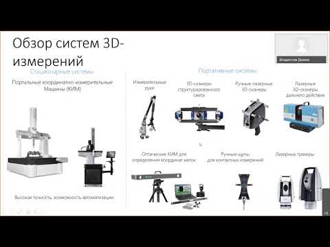
3D scanners and software: process and methods of work | Non-contact measurements | Additive manufacturing | Verification and simulation
Metrology scanners help manufacturers solve a variety of tasks, and improved software products enable engineers to process scan data more efficiently.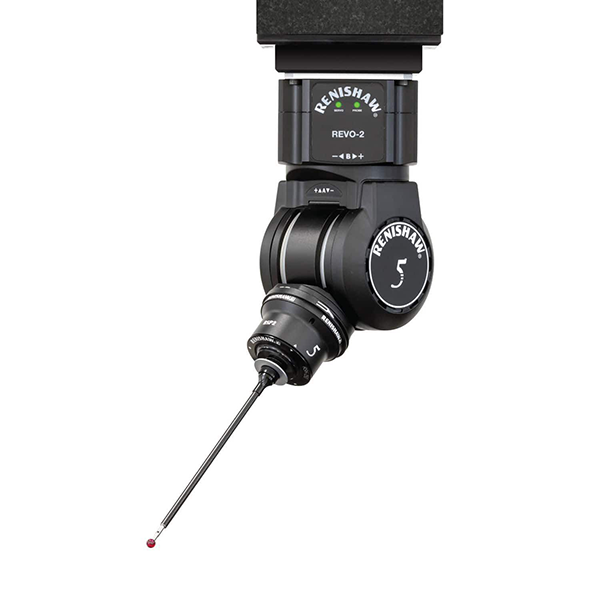 nine0003
According to Creaform's Dan Brown, manufacturing companies need reverse engineering in a variety of situations. For example, old parts that still work today may have been designed before the advent of CAD. Sometimes details are refined during use, after which it is necessary to make changes to the CAD models. In many cases, CAD models exist but are not available for various reasons related to competition and trade secrets. Comparative tests and competitive analysis are also an important area of using reverse engineering. Another problem solved by 3D scanning and modeling is quality control. nine0003
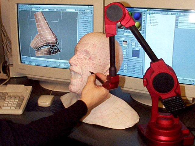
Old, proven parts sometimes need to be copied. In particular, reverse engineering is often used in the aerospace industry, usually to modify existing aircraft for new missions. A common situation is the conversion of an aircraft for aerial photography. In this case, engineers need to scan the fuselage and create a CAD model in order to make design changes to accommodate the camera.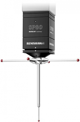 Another example of the use of reverse engineering is the creation of aircraft cockpit models for virtual training sessions in conditions close to real. nine0003
“Reverse engineering is especially effective for mold tooling because molds are often modified by hand after they are made,” says Dan. “At some point, the manufacturer realizes that the original CAD model is outdated, and with the help of reverse engineering, corrects it in accordance with the changes.”
Reverse engineering is even being used in high-tech jet engine manufacturing: Creaform once scanned an entire engine for a manufacturer who only had 2D drawings and needed a 3D model “to keep up with the times.” nine0003
3D Scanners and Software: Process and Methods
“We realized that 3D scanners are ideal for reverse engineering,” says Brown, noting the high portability and convenience of the Creaform HandySCAN handheld scanner. The company's other product, MetraSCAN, is larger, but its results are more accurate. At the same time, he notes that even with the fastest 3D scanner in reverse engineering, the role of a person is very important. “Clients often think it's as simple as scanning a surface, pressing a button, creating a model,” Brown says. “But the reality is much more complicated.” nine0003
Creaform MetraSCAN 3D metrology-class 3D scanner is a modern alternative to traditional CMMs for measuring large objects from 3 m with an accuracy of 0.030 mm / Photo: Creaform
It is to bridge the gap between 3D scanning and CAD that the company offers its own proprietary VXmodel software.
The first step after collecting point cloud data is to create a closed mesh and align it to a common reference plane. “Of course, point cloud data is never perfect. The first mesh can, for example, display holes,” explains Dan. nine0003
iQB Technologies experts recommend article: Getting Started with a 3D Scanner: Interview with Creaform CEO Daniel Brown
The next step in reverse engineering is not to reproduce a clean mesh file, but to refine the design requirements. In this case, the resulting grid is used as reference data. “For example, if you got a taper angle of 1.9° in your scan, it's possible that the design was 2°,” Dan says. Scanned Length 1.98 m may well be 2 meters. That is why a person should analyze the mesh when creating a CAD model - he is able to adequately interpret the results.
Dan Brown also emphasized that the VXmodel program does not create a CAD model. It transfers the geometry data directly to the software used by the customer, which in turn creates a native CAD model based on this data.
Non-contact measurements
“The choice of metrology device is largely dependent on what part is being reverse engineered,” says Steve DeRiemer of Capture 3D, the exclusive distributor for GOM GmbH in North America. “Parts with a small number of holes, a simple prismatic shape and primitive elements – cylinders, planes, circles – can be measured with a CMM.”
However, for products with many rounds and complex shapes (such as in the aerospace industry), metrology devices are needed that can “acquire data from each element of the part, otherwise reverse engineering is very difficult,” notes DeRimer.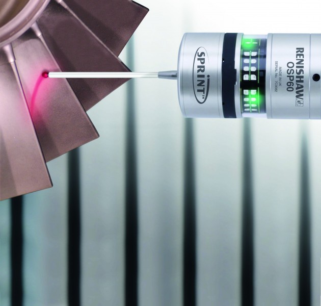 – This has become one of the main advantages of optical systems such as ATOS Triple Scan. They are able to provide the customer with what we call a "full blown part definition". Optical systems collect all possible data.” nine0003
He also explains that the resulting data is "highly organized" and is a relatively uniform, smooth area. “High quality data improves the efficiency of reverse engineering,” concludes Steve DeRiemer.
Capture 3D provides software for converting point cloud data to a mesh, but for the next step, creating a CAD model, the company uses third-party software. The two most popular programs in the industry, according to Steve, are PolyWorks from InnovMetric and Geomagic Design X from 3D Systems. nine0003
3D model created with Geomagic Design X / Photo: 3D Systems
DeRiemer keeps a close eye on the development of the programs that are used to create CAD models. “Major CAD developers are constantly releasing add-ons to their core products that make reverse engineering easier.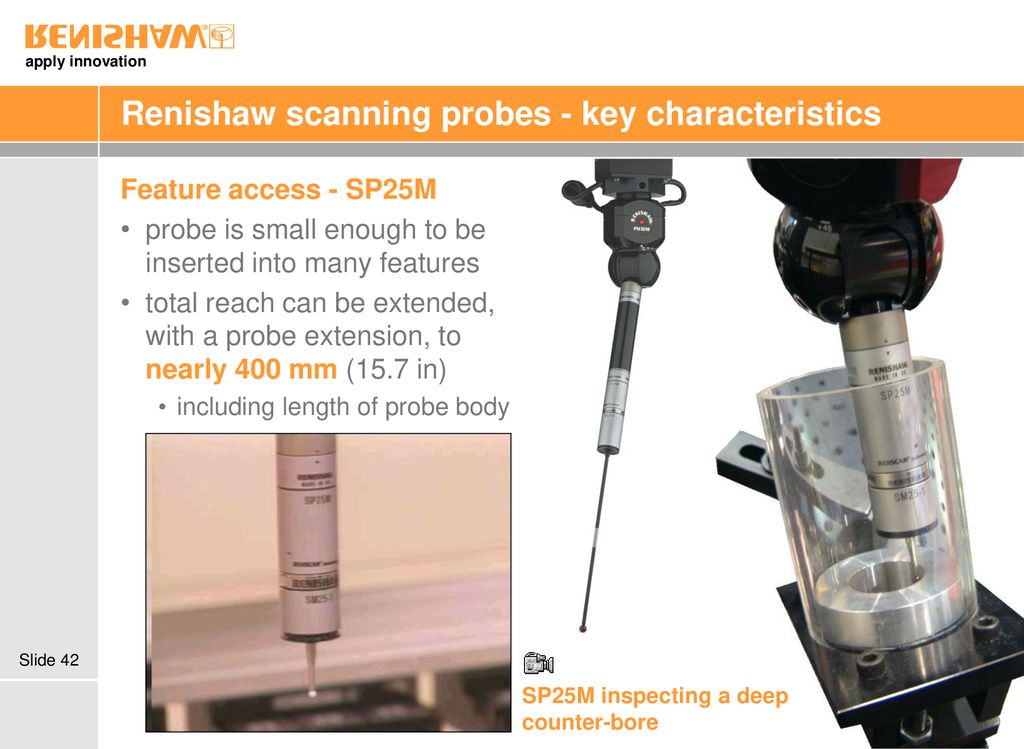 They work with polygonal meshes, and their functions have long become much wider than just rotating the model along three axes. Now you can create sections and curves in polygon meshes, overlap surfaces and start building a CAD model manually,” explains Steve. The functions of such add-ons are further enhanced by recognition algorithms that identify critical elements on a polygonal mesh. nine0003
iQB Technologies experts recommend article: Fast and easy reverse engineering: professionals choose Geomagic Design X
Additive manufacturing
Another industry where reverse engineering plays a very important role is additive manufacturing.
“3D printing is used for a variety of applications, from custom fasteners and tooling to prototyping and custom manufacturing,” says Alicona President Stefan Scherer. And one of the promising areas of using these technologies is the reproduction of products. For example, an engineer scans a critical but failed part, reverse-engineers it, and then manufactures it using additive manufacturing.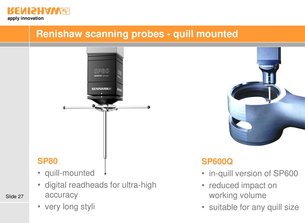 ” nine0003
In this context, the popularity of the STL format is especially valuable - when using it, you do not need to recreate the CAD file, since the STL is specifically created for 3D printing. This eliminates many of the problems associated with creating a CAD file from a polygon mesh (although cleaning the mesh of holes and reflections is still required in order to create a quality print program for an additive setup).
“Creating a CAD model, in addition to mesh cleaning, also requires special knowledge on the part of the operator. This is due to the fact that CAD models are based on the description of primitives (cones, spheres, cylinders, etc.) and not polygonal meshes,” Stefan explains. nine0003
Alicona measurement equipment uses focus change to capture high resolution solid object data. Despite the fact that the technology is similar to the well-known single focus, it differs from the latter by using only reflected light, i.e. completely passive.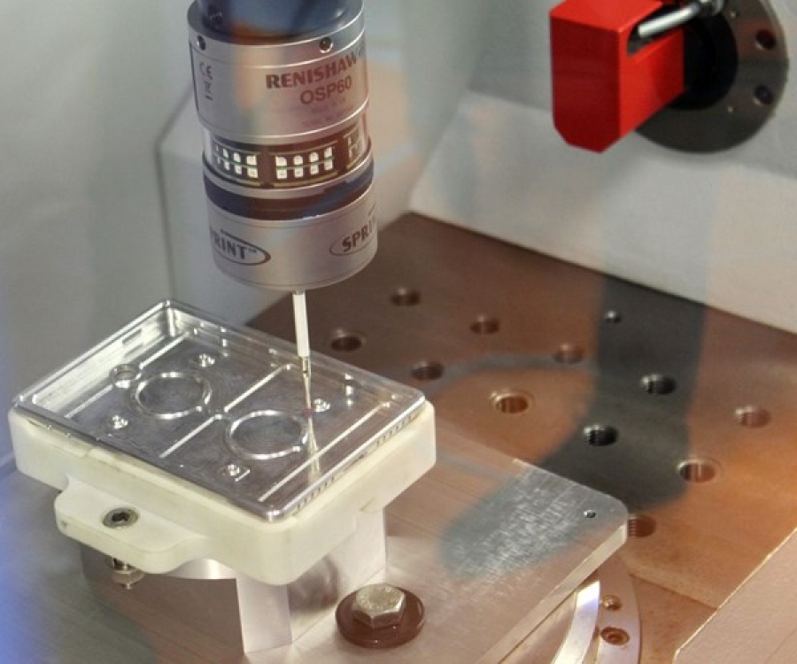
Converting a point cloud from a metrology scanner to a polygon is an important step in reverse engineering... but only the first step / Photo: Creaform nine0003
Verification and simulation
“When we talk about reverse engineering, we can have at least two different concepts in mind,” says Renishaw's Michael Litvin.
The first is to analyze the features of the part, recreate the drawing or CAD model, and then manufacture the part based on the extracted information. The second is to verify that the part meets the manufacturer's specifications using engineering analysis software, such as finite element analysis or dynamic flow simulation. nine0003
“In this case, you already have both the CAD model and the manufactured part. But in doing so, you need to understand how it is produced and how it affects its quality, and to do this, you compare the data of engineering analysis tools with theoretical values from CAD,” adds Michael.
It is for these purposes that the company has developed Sirfit Blade, an add-on module to the point cloud conversion packages APEXBlade and MODUS. APEXBlade allows you to plan and create DMIS-compliant part programs using five-axis blade geometries using the REVO stylus, which can be installed on most existing CMMs. nine0003
“Being able to analyze a real blade is very important because it allows us to calculate the performance and efficiency of an engine before it is assembled and tested,” says Litvin. The same can be done using the original CAD model, but such an analysis is based on a theoretical, ideal part, and we all know that the real part very often differs from the theoretical one. He adds that such an analysis requires the collection of complete blade surface data, which is successfully provided by a program that creates an IGES-compatible CAD model. nine0003
Author: Bruce Maury. Original article at advancedmanufacturing.org. The material is abbreviated.
Article published on 07/25/2019, updated on 03/03/2022
Welcome to Expo Control 2021
Toggle Nav
Back
August 14, 2021 nine0003
We invite you to the 12th thematic exhibition of equipment and tools for industrial measurements "Expo Control 2021".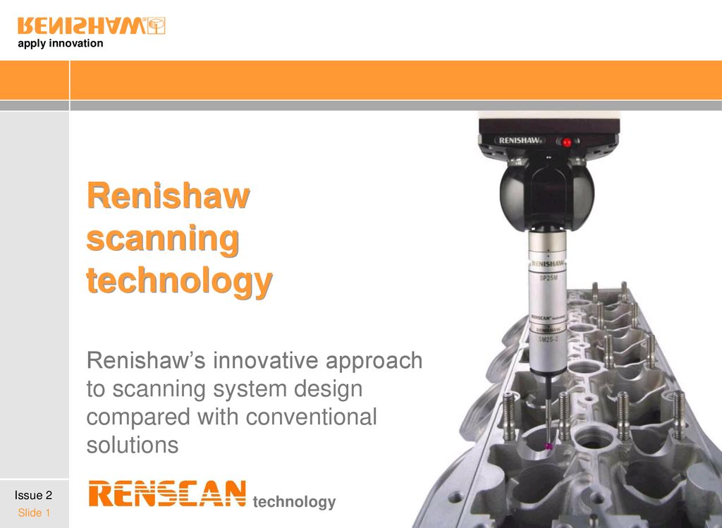 The exhibition will be held from 7 to 9 September 2021 in Moscow at the Expocentre Fairgrounds.
Expo Control is a major annual event that brings together a narrow circle of metrologists, engineers, technologists, designers, and other specialists.
In 2021 at the Norgau booth you will see:
NORGAU NCMM-686 Coordinate Measuring Machine
The NORGAU NCMM-686 CMM is the solution for today's businesses that are ready to move beyond manual measurement to the next level. Kit includes: Renishaw Ph20 contact head, SP25 scanning probe, 0.1 µm scales, Renishav controller and automatic stylus changer magazine.
Video measuring system NVM-PRO
NVM-PRO is the result of many years of work of designers and technologists of Norgau. This microscope meets all world requirements in the field of optical and contact linear-angular measurements. Several standard sizes are available from 150x150 mm to 500x400 mm. All models can be equipped with optical and contact sensors for both 2D and 3D measurements. nine0003
New generation scales with a resolution of 0.1 µm have improved the accuracy and repeatability of the results obtained. Precision measurements of parts can be carried out with an accuracy of 1.2 µm.
NVMicro Inspection Microscope
NVMicro is a new auto focus inspection microscope. On it it is possible to carry out control of products, keeping the image and video in high resolution.
NVMicro is suitable for inspecting small parts with 0.1mm accuracy, enlarged image is transmitted to the monitor screen, it can be saved, select and enlarge a separate area, take measurements within the screen. nine0003
3D Scanner HandySCAN BLACK|Elite
Metrology-grade 3D scanner with patented technology for unsurpassed scanning speed and quality.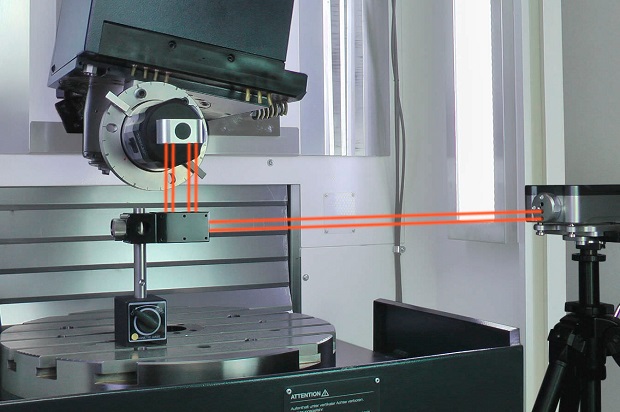 The weight of the scanner is less than 1 kg.
Easily scans glare without losing quality or accuracy. Measurement speed up to 1.3 million measurements per second. Accuracy 0.025 mm. Entered in the state register SI 78749-20
MarShaftScope 350
MahrShaft Scope optical shaft measuring system with high precision rotation axis and vertical measuring axis with a range of 350 mm. The system is equipped with a fast optical sensor for measuring diameters and linear dimensions and a contact module with an inductive sensor for measuring end runout, keyways and other hard-to-reach parameters and places that are difficult to control with an optical camera.
In addition, the stand will feature:
- CNC viewing microscopes;
- measuring equipment with wireless data transmission;
- special software for the collection and analysis of measured data, the definition of a quality indicator and the analysis of measuring systems;
- torque tool ruler;
- set for measuring the internal and external dimensions of complex parts;
- AVANT and CV2100 contourographs, RA-120P and RA-2200 round meters, LSM-503 laser micrometer, TM-505, MF-A2010, MF-U2017 optical microscopes; nine0162
- I-Checker indicator and bore tester, SJ-210/SJ-310/SJ410/SJ500P profilometers, HR-530 b HV hardness testers;
- iQB 3D design and modeling solutions;
- Metrascan BlackIElite, Solutionix C500 3D scanners and solutions for 3D design, modeling and printing of parts.
Learn more