Rat rig 3d printer
Rat Rig V-Core 3.1 - Configurable kit
Project Page
The V-Core 3 is a premium DIY kit for a CoreXY 3D Printer with no compromises. Learn everything about the V-Core 3 on the dedicated project page: v-core.ratrig.com.
Looking for a pre-configured machine?
This "Configurable kit" is meant for advanced users who know what they're doing and want to have control over what components go into their machine. If you're just looking for a kit as complete as possible and don't want too many choices, you should probably be looking at the V-Core 3 Standard Kit.
Compatible Extruders / Hot-ends
Via the EVA modular carriage system, the V-Core 3 currently supports many different extruders and hot-ends, allowing you to mount them on your machine in any combination you want.
You can check all available configurations at main.eva-3d.page
At the moment, we're only printing EVA parts for the extruders/hot-ends we supply. If you’d like to use other combinations, you will need to print the respective mounts yourself! STLs are available in the link above. Your EVA printed parts will be printed in accordance with the extruder/hot-end you select in the configurator. If you don't select an extruder or hot-end on the configurator, your printed part set will ship without those printed parts. In this situation, you can print the parts yourself using the STLs available in the EVA page linked above.
Not included
 Using 4mm thick polycarbonate sheets is suggested (CAUTION: thickness above 4mm is not advised as it will interfere with the XY motors).
To extend the cabling of your fans and bltouch:
2x 22AWG Cable 2 Conductors 1500mm
1x 22AWG Cable 5 Conductors 1500mm
To connect PSU, SSR and board:
3x 16AWG Cable 2 Conductors 500mm
Enclosure Kit
Learn more about the V-Core Enclosure Kit on the dedicated product page.
Spool Holder Kit
Learn more about the Spool Holder Kit on the dedicated product page.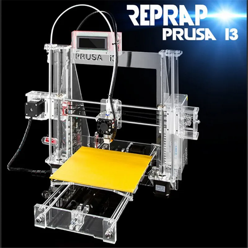
Workbench
The V-Core 3 Workbench is one of the options on our MESH WorkBench - Light product line.
The V-Core 3 is a premium DIY kit for a CoreXY 3D Printer with no compromises.
This kit is the culmination of Rat Rig's accumulated years of experience designing, producing and distributing DIY 3D Printer kits worldwide. Originally introduced in 2017, the V-Core went through several iterations and multiple variants over time, through a process of continuously seeking user feedback to drive product development. The lessons learned over the years allowed us to understand what works and what doesn't, what features are most valued by users, and what choices ensure both quality and affordability. We've distilled all this knowledge into the V-Core 3, which was designed in partnership with Pawel Kucmus, a long time member of our on-line community and one of the most prolific contributors to the V-Core platform.
Precision
The V-Core 3 uses 3 lead screws to drive the Z axis of the machine.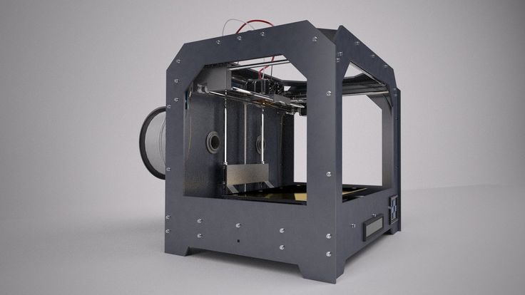 They move the bed down in small increments, at the end of each complete layer. The Z axis moves very slowly, so speed is not the priority - precision and resolution are.
The V-Core 3 uses TR8X4mm lead screws instead of the TR8x8mm used in previous machines, effectively halving the pitch of the lead screw - this means that each rotation of the motor, now moves the bed half as much.
This both doubles the Z resolution of your layers and multiplies the holding torque - always helpful when you're moving such a heavy bed, especially on the larger variants.
They move the bed down in small increments, at the end of each complete layer. The Z axis moves very slowly, so speed is not the priority - precision and resolution are.
The V-Core 3 uses TR8X4mm lead screws instead of the TR8x8mm used in previous machines, effectively halving the pitch of the lead screw - this means that each rotation of the motor, now moves the bed half as much.
This both doubles the Z resolution of your layers and multiplies the holding torque - always helpful when you're moving such a heavy bed, especially on the larger variants.
Robustness
While previous V-Core versions, like many other printers on the market, relied solely on 20 Series profiles, the V-Core 3 is fully built on a 30 Series aluminium frame. From screws and nuts to brackets and plates, everything is bigger, stronger and tougher.
- Frame made with 30x30mm T-Slot aluminium with a beautiful black anodization
- 4mm thick anodized aluminium plates
- 9mm Belts
- Weight of Z drivetrain and bed is distributed across the Z motor mounts - not on the motors themselves
Customization
- Available both as a complete kit and a configurable kit (for those who want to select their own electronics)
- Configurable options include LDO motors, Keenovo Heat pads, and multiple controller board options (from Duet3D, SKR, etc)
- 4 build volumes available as standard option: 200, 300, 400 and 500 mm3
- Full End Stop solutions
- EVA 3 Carriage System provides mounts for most popular extruder and hot end choices on the market
- Shipping with EVA 3.
 0.2
0.2
What is EVA?
EVA is an independently developed and maintained project that aims to be a single platform for many extrusion types.
Note that not all print head types (due to their physical dimensions) can reach the full print area.
EVA 3 is the next iteration of the EVA platform with which V-Core 3 is fully compatible.
Read more about EVA on: EVA 3 Documentation
Support
- Fully comprehensive step-by-step build guide (Both static and video)
- Fully comprehensive wiring and electronics guide for multiple controller boards
- Support configuration files for several firmware choices (Reprap, Klipper)
- Join our Facebook 3D Printer Community to connect with other V-Core users, share builds, knowledge, mods, and stay posted on all V-Core 3 developments.
Safety
- Wiring design includes multiple cable management parts, for cable clamping, guiding and strain relief
- Custom Keenovo Heat Pad with pre-wired 157ºC Thermal Fuse for extra safety (Optional).
 The wiring comes out of the pad slightly off-center, so it's neatly guided to the back of the machine without interfering with the bed mounting point at the back.
- For 120/220V Heat pad users, grounding point at the bed and fully isolated bed from the rest of the printer means that the printer frame is never conducting any dangerous voltages.
Convenience
- Designed for a far easier and quicker assembly than previous versions
- Separate chamber for electronics ensures heat insulation, short motor cable path, easy access to all wiring, and a very clean installation
*Panel for mounting electronics is not supplied, user is meant to source it locally. A 4mm thick polycarbonate sheet is suggested. Mounting screws and nuts are included as part of the base kit. DXF files with size, shape and hole patterns for the panels are provided on the project documentation.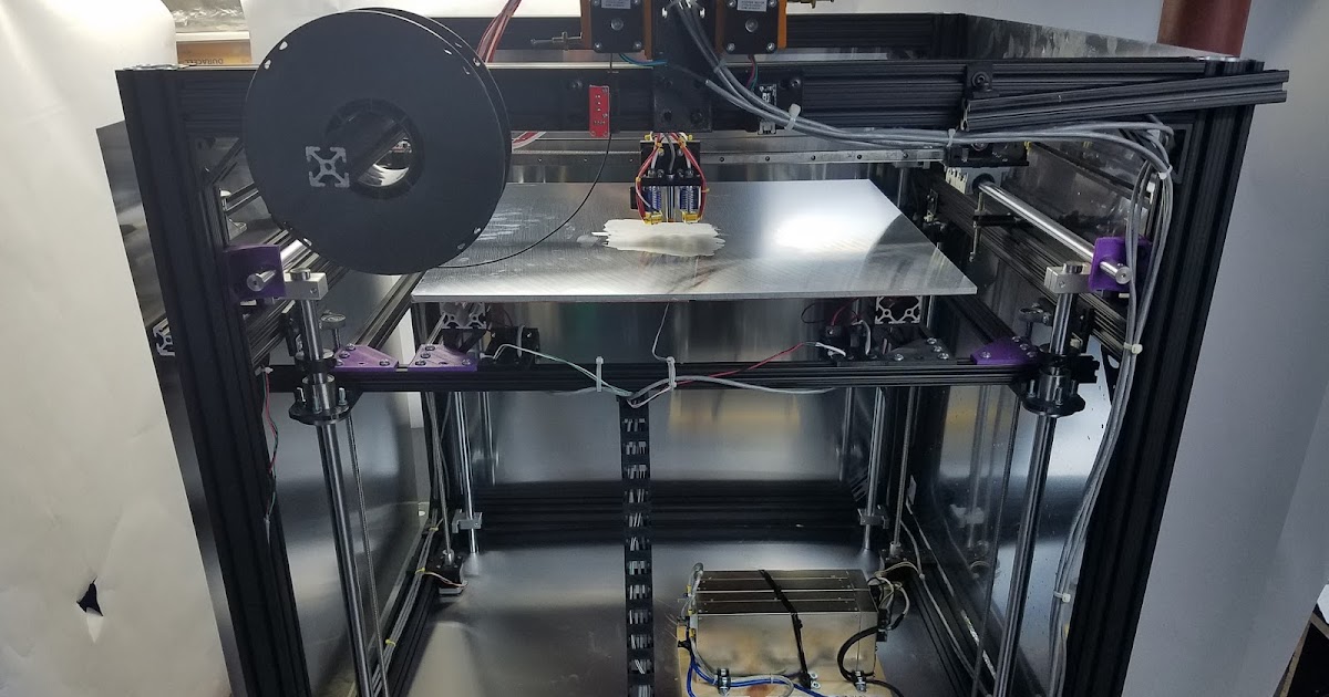
Electronics Panel should not be thicker than 4mm, otherwise it will not fit in the available space.
Fully Enclosable
Enclosure Kit
The V-Core 3 was designed from the ground up with full enclosing in mind, with no need for an external enclosure. The design ensures that all motors and electronics are safely placed outside the printing chamber, so they are shielded from high temperatures, and no machine elements protrude from the frame, ensuring that the frame can be directly covered with panels from all sides.
In-Lid Spool Holder
Our in-house spool holder was also designed with the V-Core 3 enclosure in mind. It can be securely installed inside the V-Core 3 lid, allowing your spool to stay tidy and neat.
Modding
The V-Core 3 is the perfect printer for advanced users who like to tweak and tinker with their machine:
- Fully open-source design, with downloadable 3D models and part libraries freely available
- Frame is built on a modular platform of T-Slot and V-Slot profiles, which allow for endless possibilites when it comes to mounting all types of parts
- Vast catalog of stand-alone parts available for infinite upgradeability: screws, nuts, connectors, brackets, pulleys, belts, electronics, etc
- For some inspiration, check out the V-Core 3 Gallery with builds from users worldwide
Dimensions
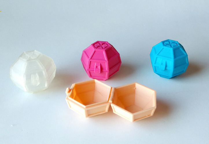
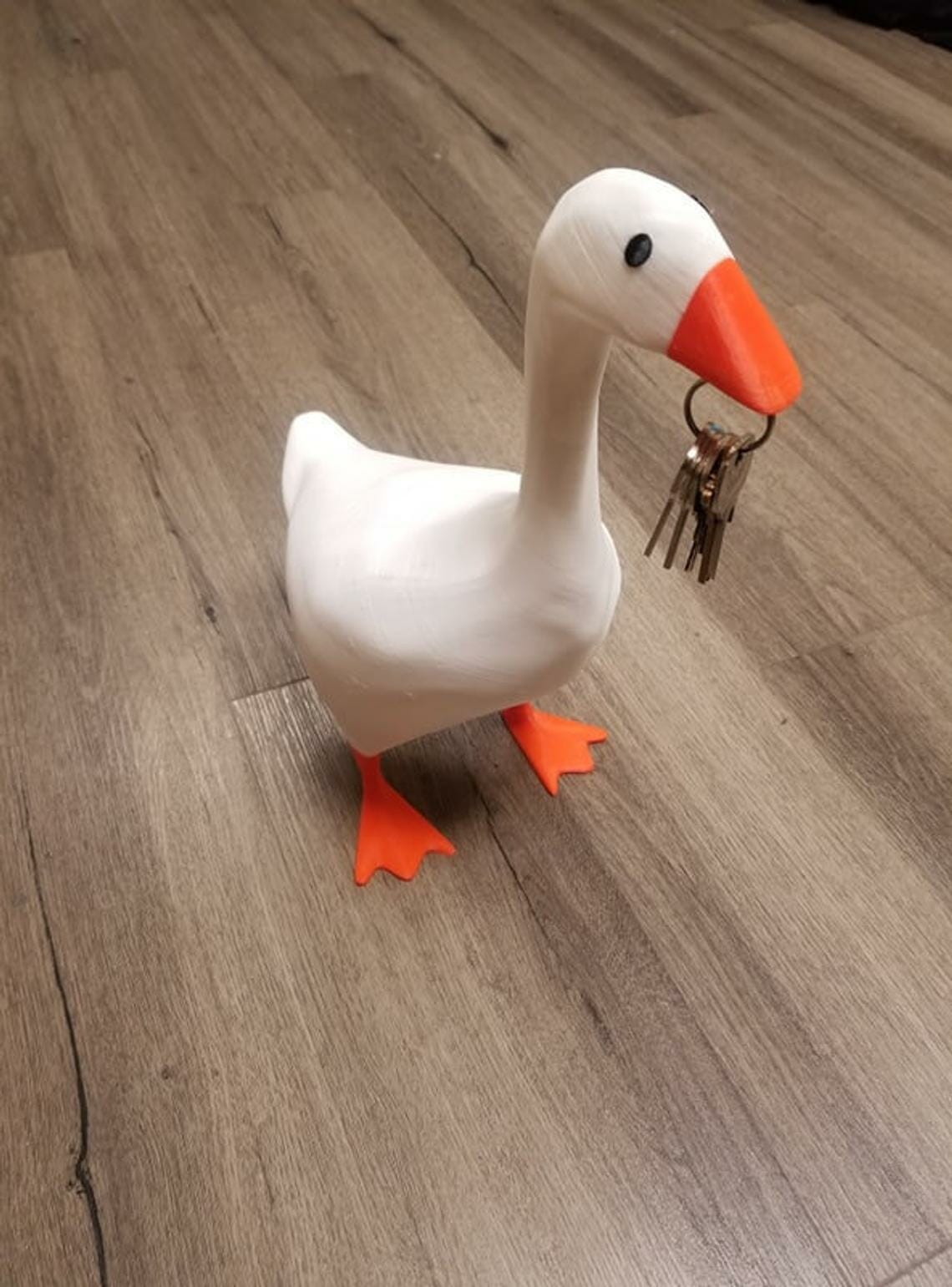
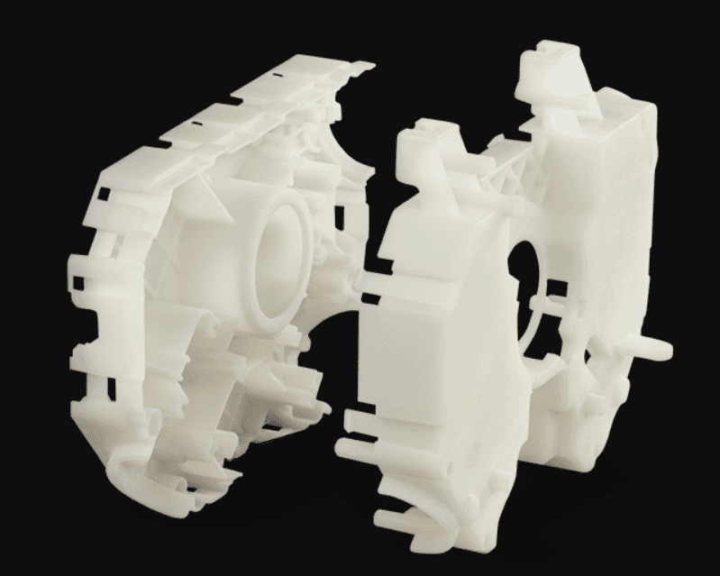
Sample Prints / Parts
These images showcase 3D prints produced by V-Core 3 machines belonging to members of our community.
Acknowledgments
As an Open-source project, the V-Core 3 design is the result of prolonged brainstorming, testing, and collaboration between many active members of the international 3D Printer Community, who shared their knowledge and experience with our design team. As such, the machine inevitably draws inspiration from and builds upon many existing design elements that have been developed, shared, tested, modded, and iterated by the community at large. The nature of the open-source movement makes it often difficult to trace back where each idea was originally generated, making it hard to produce a comprehensive list of acknowledgments. Nevertheless, below we list a few names and projects that we would like to credit for their direct or indirect contribution/inspiration to the V-Core 3 platform (in no particular order):
- - Hypercube by Tech3c
- - Voron
- - BLV
- - Jubilee
- - Simon Davie
- - João Barros
- - Detlev Rackow
- - Márcio Pereira
- - Eduardo Oliveira
- - Mikkel Schmidt
- - Harald Wagener
- - Antonios Antzoulatos
- - Lukas Sinitsch
- - Tomasz Paluszkiewicz
License
This work is licensed under a Creative Commons Attribution-NonCommercial-ShareAlike 4. 0 International
You may share, remix and mod the design. By default, you may not use the design and its derivatives for commercial purposes, but if you request a commercial license from us, we may (and most likely will) grant you one, as long as we deem your goals are aligned with the best interests of the project and its users.
The spirit of the project is to remove barriers to innovation and focus on pushing the technology, working as a collective, inspiring each other and experimenting with new ideas. We are happy to foster a rich ecosystem of suppliers and services that empowers users by offering them more options and alternatives.
Videos
Rat Rig 3D Printer Review - V-Core 3- Part 1
Part 1 of a 3 part series for the Rat Rig 3D printer review. Let's examine the part sourcing and mechanical build for a V-Core 3.
A new coreXY contender in the 3D printing world is garnering some attention and gaining popularity as of late, the Rat Rig V-Core 3 corexy 3D Printer. In the coming weeks we will be doing a 3 part series on the printer, comprising of the mechanical build, wiring/first prints, and finally the final verdict on the printer.
This article is part 1 of the Rat Rig V-Core 3 3D printer review series, consisting of the part sourcing process and the mechanical build of the printer.
Disclaimer: Rat Rig provided the mechanical kit, free of charge, for the purposes of review. However, Rat Rig has not influenced the review process in any way and these thoughts and opinions are my own.
Introduction
Rat Rig appears to have started as a company making camera sliders as far back as 2014 from the About Us section of their website. Rat Rig is based out of Europe. Their values as a company are centered around providing modular components, that are simplified and not overly complex, and high quality. In addition to camera sliders they began to make 3D printer kits, the one we’ll be talking bout today is the V-Core 3, which has been developed based on years of experience from it’s predecessors launched back in 2017.
When this process began in mid May of this year, 2021, I ordered the V-Core 3 300mm version as a mechanical kit. At the time they did not provide 120v heatbeds and I wanted to also shop local where possible. I ordered the base Mechanical kit which consisted of the frame, hardware, linear rails, lead screws, bed plate, magnet and flexible build sheets. I purchased most the remaining parts and PETG filament from Sparta3D based out of Ontario, Canada.
The kit arrived in 3 separate packages, delivered by DHL, approximately 8 weeks later. The parts were fairly well packed and nothing was damaged in transit which I was happy to see. The lead time posted on the Rat Rig website is currently 6 weeks. Some users are reporting that its been taking longer, but hopefully the lead time slowly reduces as time goes on.
I printed all the components, which was easy to do. The source files, CAD, and printing guidelines are here. You will need to refer to the orientation section of the above links as when you download the parts they are not in the correct orientation. I hope that in the future Rat Rig will both save the STLs in the correct orientation and adopt a better naming convention which shows quantity of parts and even if the colour is intended to be a main colour or accent colour. One feature I quite enjoyed about printing the Rat Rig parts is that they implement sacrificial layers to “trick” the printer into printing bridges instead of requiring support structures. These sacrificial layers are to be removed during part prep prior to the build:
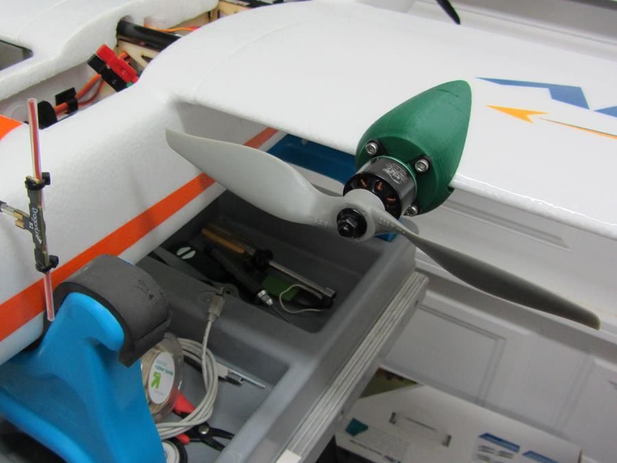
I choose to print Sparta3D’s PETG with the light blue main colour, and black accent colour. The filament printed really nicely on my Prusa Bear sliced in Prusaslicer and the blue looks fantastic, in my opinion, with the black frame. I also chose to print the front fan shroud in transparent blue resin.
The Build
Now that I had the kit, the parts, and the printed parts complete it was time to build and begin this Rat Rig 3D printer review. I went to the Rat Rig V-Core 3 Build Guide to start the build process. The guide is pretty clear and I think I only stumbled in one or two spots where comments in the build guide helped me out. I also opened their CAD file for reference in Onshape as well.
I started in the preparations section where it references the belt prep, printed part prep, and the assembly nuts insertion process. After that I went through each section, meticulously to get the build up and running.
Here’s how long it took me to complete each mechanical section, up to the wiring stage:
01. Frame assembly: 3.25 Hours
02. XY Drive Assembly: 2 Hours
03. XY Idler Assembly: 0.5 Hours
04. Z motor mounts: 0.5 Hours
05. Linear rails: 1 Hour
06. X gantry: 2.25 Hours
07. Bed Assembly: 2 Hours
08. EVA: 1 Hour
Check out the progress of my build in this gallery:
Throughout the build I only encountered 2 quality control issues from the components that I received from Rat Rig. The first was that one linear rail had one 3mm holes that was not drilled through from the factory. This in my opinion was really a non-issue as all the other holes for that rail are filled with m3’s and t-nuts keeping the rail in place unlike other builds where you only fill every other hole. One missing hole is not going to make a difference.
The other issue I encountered was a bad 9mm idler. It had a faulty bearing and was not rolling smooth. I e-mailed Rat Rig to which they claimed they had received a bad batch of idlers from their supplier and some made their way into kits. The also mentioned they’ve been sending out replacements to hose who received them and within a week I had a set of new idlers in my mail box. I want to also mention the idlers use MR104ZZ bearings which were relatively easy to find locally and swap out for future issues.
The build itself was pretty straight forward honestly. Getting the frame to be square and straight was not difficult and assembling 3030 extrusion components were a treat. There were only 3 areas I had to focus on, running the belts for XY, aligning the X Gantry for smooth motion, and trying to line of the Z leadscrews to be straight and parallel to the linear rail. Taking your time and really getting those steps right are going to make a significant difference in final print quality when I get to that stage.
Up to this stage things have gone well.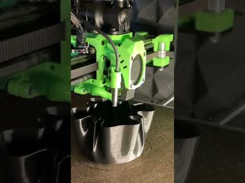 The next article will focus on the wiring and first impressions of the printer once it’s commissioned, up and running. Part 3 will be the final review article after a few hundred hours of use. Stay tuned for Part 2 and I hope you follow along as I go during this Rat Rig 3D printer review.
Category: Reviews and Buying GuidesTag: 3d printers, 3d printing, corexy, rat rig
instruction how to work from scratch for beginners and dummies, how
looks likeThree-dimensional printing has become increasingly introduced into our daily lives. Thanks to new technologies, it has become possible to easily print from a small detail to a large building. The range of products is also pleasing - today you can find a lineup that includes both affordable devices and more expensive ones. But how to work with a 3D printer? This is a completely normal question that any beginner will have, it is for this reason that we will try to answer it as simply and accessible as possible.
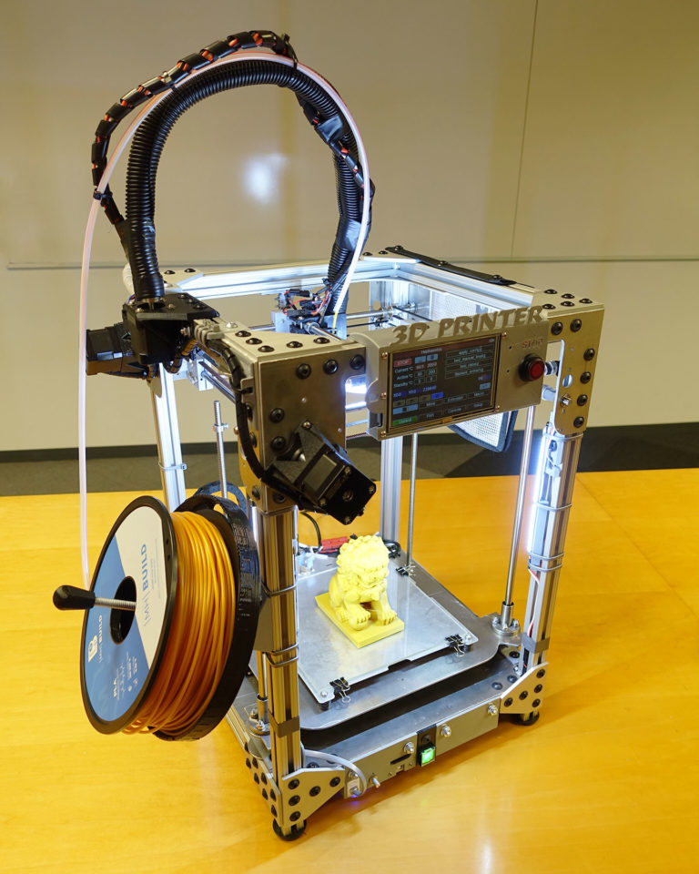
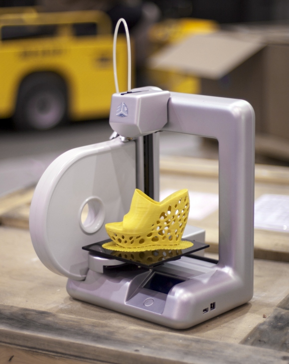
What is a 3D printer and how does it work?
The 3D device consists of the printer itself and a computer that controls all processes.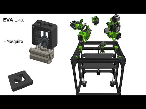 The principle of operation of such a design is to create 3D models by superimposing layers of liquid material. There are a large number of printer models - from large industrial ones to compact ones, but they all have the same principle of operation and component parts:
- Extruder - the print head through which the thread passes. The head heats the thread to a semi-liquid state and evenly supplies the material to the working surface.
- Work surface - a printing platform on which a 3D model is formed.
- Motors - mechanisms responsible for the accuracy of movement and speed of printing.
- Sensors are electronic devices that limit moving parts to specified coordinates.
- The frame is the structure that connects all parts of the printer.
How a 3D printer works: features
Work with the aim of building a three-dimensional model begins with a sketch, which is created in a special program. After that, the software independently generates a plan for the movement of the print head and a print sequence.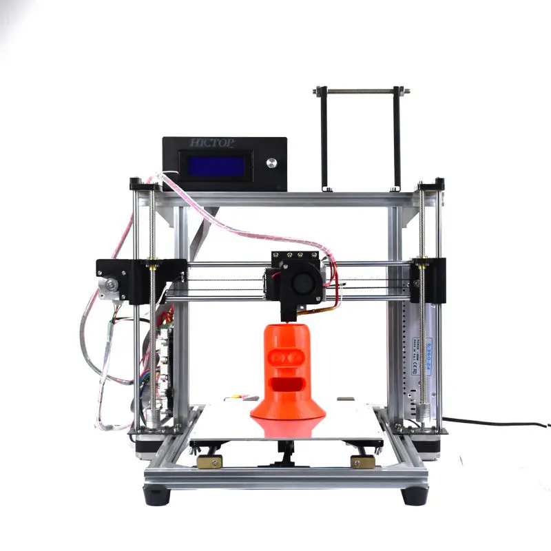 The 3D model is reproduced by strongly heating the plastic and distributing it evenly.
3D printers are used in many areas. Let's list some of them:
- Architecture - creation of models of buildings.
- Medicine - dental prosthetics, making models of organs for study.
- Construction - production of houses using 3D printing technology.
- Education - a visual aid for learning 3D printing.
- Automotive - creation of tuning parts, prototype layouts and other products.
This is a small list of industries where 3D printing is actively used. Today, almost every entrepreneur and just an enthusiastic person can afford a printer.
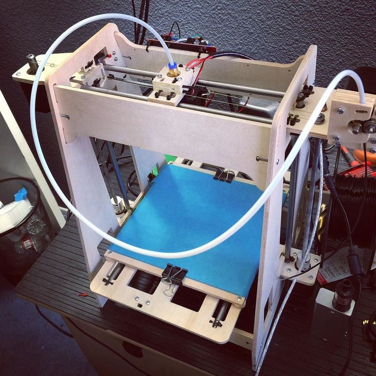
The following printers are distinguished by design features:
- RepRap - self-reproducing printers that can create their own copies.
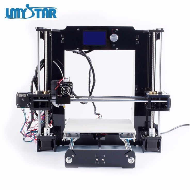
- DIY-kit - the device comes disassembled with instructions, the assembly of which will take a sufficient amount of time.
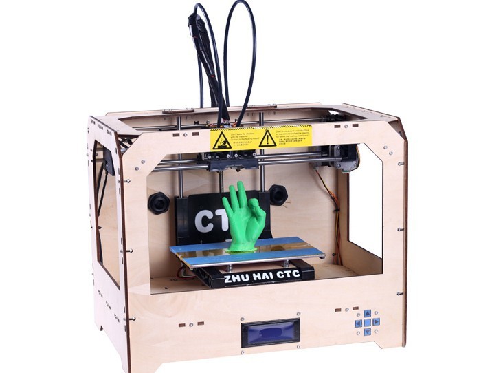
- Completed - Models are delivered assembled and ready to use.
- Commercial and Industrial - devices capable of printing metal, concrete, polymers and other materials.
How to use a 3D printer: tips for beginners, where to start
Mastering the technique of 3D printing is not difficult if you follow the recommendations and tips. Especially for those who plan to learn the basics of 3D modeling, an up-to-date list of questions and detailed answers to them has been prepared.
Printer Installation
To begin, you will need to carefully unpack the box and remove any stops. The next step is to install the printer on the surface using the building level. This will allow you to place the device as evenly as possible, which will provide better printing.
Note. Some 3D printers come with a level for installation.
Next, you will need to connect the printer to your computer and install the necessary drivers.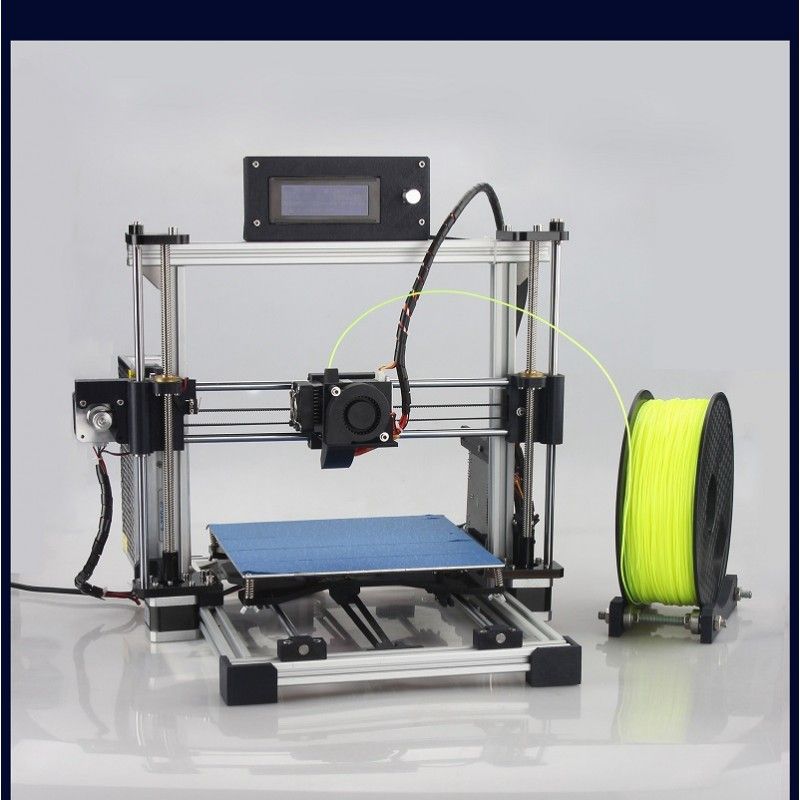 The software disc comes with the 3D device.
Preparation for work
To get started, you need to calibrate the working surface - without this, printing quality products is impossible. This process is carried out automatically or manually. The attached instructions have detailed information on how to perform manual calibration.
Extruder patency test
The next important step is setting up the extruder. First of all, you will need to check its nozzle. If the printer has already been used, the nozzle should be cleaned of solidified particles that will interfere with the throughput of the material. Refueling the 3D printer The thread is fed into the extruder directly from the spool. But there is one caveat - for this you must first warm it up. To thread the thread, you will have to make a small effort in order to loosen the presser mechanism.
Working with models
Models can be created using a variety of 3D modeling programs.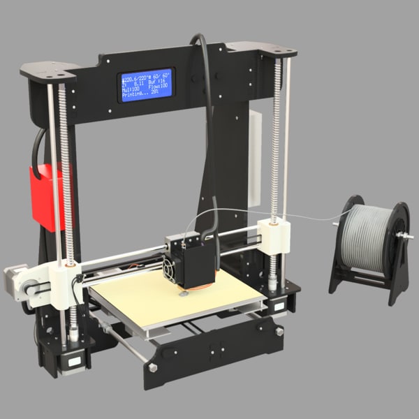 The process of manufacturing three-dimensional parts is creative, requiring careful preparation. The better and more detailed the model is drawn, the better the 3D layout will be at the output.
Start printing
After creating the model in the program and preparing the printer for work, you need to send the file for printing and wait for the result. The print speed varies depending on the printer model and specifications, as well as the media used.
Processing the finished product
3D printed products usually do not please the user with an ideal appearance: the parts have an uneven surface. But this is typical for models of 3D printers on FDM, SLA and DLP devices, which are distinguished by higher print quality. Owners of FDM printers should not despair - a simple processing of products will give products an attractive appearance and make the surface smooth.
Several powerful ways to post-process 3D printed parts:
- Mechanical - carried out by sanding the surface with sandpaper or a special sponge for grinding.
- Chemical - Surface treatment with aggressive solvents such as acetone and dichloroethane.
- Mixed - In this case, the above two processing methods are used.
What are the possible errors and how to avoid them?
Even a novice can master the technology of 3D printing, but, despite this, the production of the first products causes excitement for the user. Simple operation, detailed instructions and recommendations on the Internet will allow everyone to deal with almost any printer model. But there are a few useful life hacks, the knowledge of which will help you avoid typical beginner mistakes:
- Calibrate and test the 3D printer before starting work.
- Be sure to use the correct file extension for quality printing.
- Do not remove the finished product from the printer immediately after it has been processed: this may damage the part and cause defects.
- If errors occur during the 3D printing process, try restarting the device - this usually helps.
- If restarting the printer still does not help, try changing the settings or re-entering the model.
- When assembling the 3D printing devices, follow the enclosed instructions carefully.
- Use only the correct materials for your 3D printer.
- Subscribe to useful 3D printing channels and articles.
Following the above tips will allow you to set up your 3D printer, get it ready for operation and, most importantly, print your first 3D products. Choose a model according to your budget and capabilities, and it will not be difficult to master the basics of 3D modeling and get the first details if you follow the instructions and recommendations.
- March 21, 2021
- 7221
Get expert advice
Installing a platform heater on the PRUSA I3 HEPHESTOS 3D printer
When creating the Prusa i3 Hephestos 3D printer, bq deliberately chose not to install a heated platform.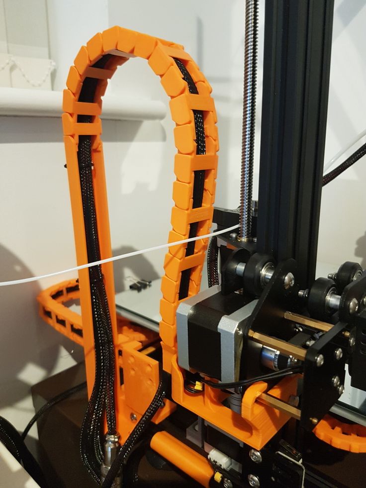 After all, it is known that for printing with materials such as PLA-plastic , bq Wood (under wood) , Flex (rubber) , nylon from T-Glass , no heating needed. At the same time, if you still decide to upgrade your 3D printer, we bring to your attention the following instructions.
For this operation you will need:
- Panel heating
- Power supply 12V 30A (5A for motors with extruder. 5-15A for panel heating. 10A should be in reserve). We use and recommend S360-12
[IMG]http://i1.wp.com/www.xn--3-7sbnb3cu7a5b.com/wp-content/uploads/2014/12/42.jpg?resize=700 %2C394[/IMG]
- Two cables with +-, conducting 180-200W each
[IMG]http://i1.wp.com/www.xn--3-7sbnb3cu7a5b.com/wp-content/uploads
And the glass didn't crack.
- 1 Thermistor (temperature measuring wire)
[IMG]http://i1.wp.com/www.xn--3-7sbnb3cu7a5b.com/wp-content/uploads/2014/12/44.jpg ?resize=345%2C345[/IMG]
The whole process is divided into 5 steps.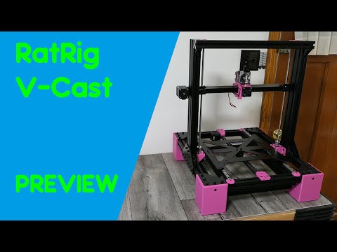
STEP 1
CONNECT POWER SUPPLY
You will need a larger transformer to operate the table heating system. We use and recommend the S360-12.
[IMG]
2) Connect two pairs of cables capable of conducting
180W each (each pair). These cables carry 12W each - to the extruder with motors and to the heated seat.
3) From the connector that is included in the board - unscrew the old adapter (pictured)
[IMG]http://i1.wp.com/www.xn--3-7sbnb3cu7a5b.com/wp-content/uploads /2014/12/46.jpg?resize=700%2C394[/IMG]
4) In its place, screw one pair from the power supply. In the two connectors adjacent to the left, screw the second pair of wires from the power supply.
[IMG]http://i2.wp.com/www.xn--3-7sbnb3cu7a5b.com/wp-content/uploads/2014/12/47.jpg?resize=700%2C666[/IMG]0003
STEP 2
PREPARE PANEL HEATING AND THERMISTOR
Connect two wires (+/-) to the heating as shown in map 2
The top side is the side with the linear heating elements.
[IMG]
There is a small hole in the middle of the panel. You need to place a thermistor (a wire that measures temperature) in it, and fix it with Kapton or blue tape from the bottom. The thermistor must not stick out of the hole on the top side. It should be in the hole.
STEP 3
CONNECT THE PANEL TO THE DESK AND CONNECT TO THE BOARD
- To connect to the table - remove the glass and black acrylic panel that came with the kit and instead, attach the heater with connectors to the side of the board.
Place the thermo glass on the panel. Or, place an aluminum plate between the supplied glass and the heated seat. Otherwise, when heated to 100, the glass may crack.
Connect the wires from the panel and the thermistor as shown on the map (Wires from the heater to the D8 connectors, and the wire from the thermistor to the connector next to the thermistor from the extruder)
[IMG]
STEP 4
FIRMWARE REPLACEMENT
By default, the code on the Prusa board does not take into account the panel heating.