Raspberry pi 3d scanner laser
OpenScan DIY 3D scanner works with Raspberry Pi, DSLR, or smartphone cameras
OpenScan is an open-source DIY 3D scanner that relies on Photogrammetry and works with Raspberry Pi camera modules, compatible ArduCam modules, as well as DSLR cameras, or the camera from your smartphone.
The open-source project was brought to my attention after I wrote about the Creality CR-Scan Lizard 3D scanner. The OpenScan kits include 3D printed parts such as gears, two stepper motors, a Raspberry Pi shield, and a Ringlight module to take photos of a particular object from different angles in an efficient manner.
OpenScan ClassicThe OpenScan Classic kit above allows for 18x18x18cm scans and comes with the following components:
- 1x Nema 17 Stepper Motor (13Ncm)
- 1x Nema 17 Stepper Motor (40Ncm)
- 2x A4988 Stepper driver
- 1x Power Supply 12V/2A (5.5-2.5mm plug)
- 1x Optional Bluetooth remote shutter control for smartphones
If you’re going to use the Raspberry Pi as shown on the right side of the image, you’ll also need
- Raspberry Pi 3B+ SBC or compatible,
- 8MP Raspberry Pi Camera 8MP with 15cm ribbon cable (or compatible like Arducam 16MP)
- 1x Pi Shield (either pre-soldered or solder-yourself)
- 1x Pi Camera Ringlight (optional but highly recommended), pre-soldered or solder-yourself
- 8x M3x8mm, 10x M3x12mm, 8x M3 nuts, 50x6mm steel rod, 2x 1m stepper motor cable
Alternatively, you could use a smartphone or a compatible DSLR camera with a ring light mounted on a tripod. There used to be an Arduino kit, but it has now been deprecated.
An alternative design is the OpenScan Mini pictured above with the Raspberry Pi camera and ring light attached to it, and suitable for scans up to 8x8x8 cm.
The system would then take photos from different angles under the same light conditions thanks to the ring light. Depending on the complexity of the object, you may have to take hundreds of photos. The photos can be imported to Photogrammetry software for processing. Open-source Photogrammetry programs include VisualSFM that’s fast but only outputs point clouds, as well as Meshroom and Colmap with mesh and texture support, but you’ll need a machine equipped with a CUDA-capable GPU for both. Meshroom is the most popular and actively developed.
There’s also the OpenScanCloud that will process the photo in the cloud with minimum user intervention. It’s free thanks to a donation, but usage is limited, and whether it can stay up and running may depend on the continuous support from donations.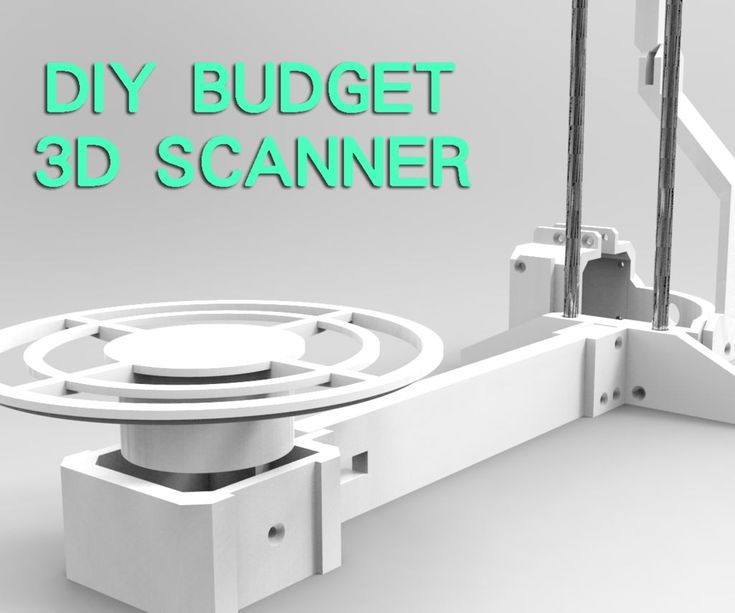 Here’s a short demo of how this all works.
You’ll find the latest Python software for Raspberry Pi and a custom Raspberry Pi OS image on Github, and 3D files for the scanner and Raspberry Pi shield on Thingiverse.
The easiest way to get started would be to purchase one of the kits directly from the project’s shop for 107 Euros and up. Note that a complete kit with pre-soldered boards, a Raspberry Pi 3B+, and an Arducam 16MP camera module goes for around 298 Euros including VAT.
It’s also possible to use photogrammetry without a kit, for example for larger objects, by simply taking photos of the object by yourself, but results can be mixed as found out by “Making for Motorsport” when comparing CR-Scan Lizard 3D scanner with photogrammetry using only a DSLR camera. It should be noted that both methods also required editing of the 3D model to remove “dirt” and adjust some shapes.
Jean-Luc Aufranc (CNXSoft)
Jean-Luc started CNX Software in 2010 as a part-time endeavor, before quitting his job as a software engineering manager, and starting to write daily news, and reviews full time later in 2011.
DIY 3D scanner leverages Raspberry Pi 4, infrared camera and SLAM | Geo Week News
Frank Zhao, an engineer at PlayStation R&D who describes his position as “seeing how to make new technology fun” has taken his personal curiosity in tinkering to the 3D scanning world – creating a DIY 3D scanner that utilizes Raspberry Pi. An early adopter and experimenter with 3D printing, Zhao has recently turned to scanning and photogrammetry. In a recent project, detailed on his blog, he set out to see if infrared cameras could fill in gaps where more traditional photogrammetry techniques struggle.
After less than stellar results with a Jetson Nano developer kit and the PlayStation camera, Zhao started looking for other inexpensive and portable options.
“I was hoping for the same results as if I were to do photogrammetry with a 1280×720 camera, but with the black spots filled in instead of just a void. Also I was hoping for enough frame rate to navigate a small indoor robot.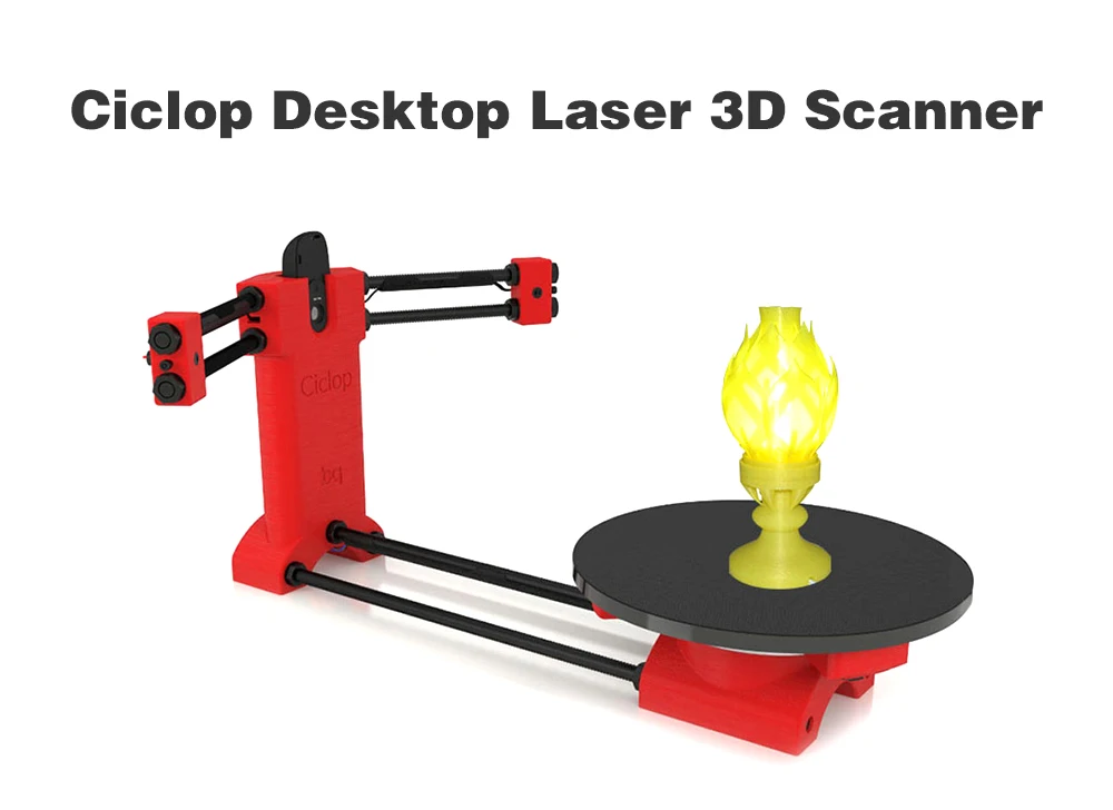 ”
”
The scanner he ended up creating is contained in a 3D printed case, backed by a Raspberry Pi 4 and an Intel RealSense D415 camera. The Intel camera is depth sensing, using infrared cameras and an onboard processor to generate depth map data for feature extraction, and also includes a normal RGB camera. That’s a lot of data to push through at once – which is why using the latest Raspberry Pi 4 for this DIY 3D scanner was crucial for this to become a reality. The Raspberry Pi’s utilizes USB 3.0 (which gives the device more bandwith) and the newer ARM core has out-of-order instruction execution, which can help to speed up the process.
In terms of the software, the Pi is running a program called RTAB-MAP (Real-time Appearance-based Mapping) which is capable of performing simultaneous location and mapping (SLAM) using the same approach as commercial SLAM scanners – where overlapping points are used to extrapolate both the location and their relative positions, explains Zhao.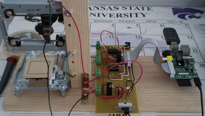
“RTAB-Map is a platform that uses a bunch of open source SLAM related libraries to do its mapping, and also provides a way for me to save the ‘database’ and generate 3D models.”
Leveraging the advantages of infraredTypical depth sensors have trouble with flat, shiny objects because of their lack of texture. The RealSense camera uses a dot projector to overlay a pattern onto the surface, so that the dots become the missing texture. The processor can then have an easier time of figuring out depth. Infrared also has the advantage of being invisible to the human eye, so it will not be distracting to light up what is being scanned with this DIY 3D scanner. This is similar to how the iPhone accomplishes its Face ID.
“Due to the amount of noise in the depth map and the lower resolution of the cameras, the resulting surface quality is poor,” commented Zhao, “However, this technique could succeed where photogrammetry fails. Remember that photogrammetry will fail on texture-less objects.”
If you want to attempt to replicate this yourself, Zhao provides details on his blog and github. Though the project was inexpensive, he warns that it his attempt was challenging from a software perspective (and was less straightforward to a “DIY kit“), and that he had to create his own installer script to overcome some incompatibility and dependencies. It is also not designed to be superior to commercial scanners.
“This device does not replace a commercially available 3D scanner, but it’s fun to wave around.”
Want more stories like this? Subscribe today!
About the Author
Carla Lauter
Editor, Geo Week News
Carla Lauter is the editor of Geo Week News, creating and curating content and newsletters in support of Geo Week. Before joining Diversified Communications, Carla spent 10 years on NASA and National Science Foundation funded projects focusing on Earth science and communication. She has worked on web-based outreach and online interactives for NASA Earth Science, including products for satellite missions measuring sea level, salinity and hyperspectral ocean color.
Get in touch:
Please enable JavaScript to view the comments powered by Disqus.
3D scanners Ciclop and Piclop
3D modeling
Subscribe to the author
Subscribe
Don't want
19
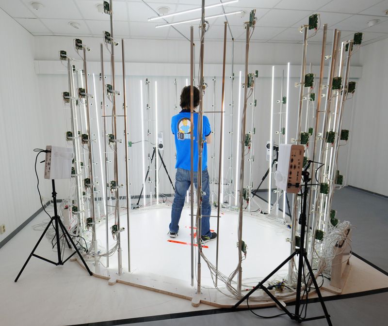
Two scanners with a similar ideology, but different hardware and software solutions. Probably the easiest way to scan a model is to place it on a turntable, illuminate it at an angle with a laser pointer with a cylindrical lens that turns a point into a vertical line, film it with a camera, and calculate the offset of the line points from the vertical caused by the model.
About 3 years ago the idea was implemented in Spain by BQ labs and published under free licenses. Details of the design for printing on a 3D printer and a very beautiful horus program written in Python were posted.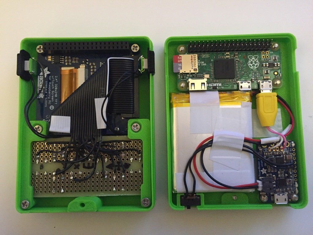 To clearly highlight the laser illumination, it was necessary to control the exposure of the camera. At the time of creation, Ubuntu 14.04 was up-to-date. V4L2 supports camera control, but it does not interface with the official version of OpenCV.
Following the principle of writing minimal custom code to get a workable result, the developers slightly tweaked the current version of OpenCV. The decision is correct, a working installation has been received, and whoever is late, let him clear up the situation in which installation on new versions of Ubuntu requires the demolition of all programs using newer versions of OpenCV. Ideologically, the system is outdated, and the authors. it was probably not interesting to edit subsequent versions, especially since this did not affect the mass consumer using Windows in their work, since this OS uses drivers from the camera manufacturer.
The community, of course, tried to solve the problem, but it seems that they did not achieve an ideal result that suits everyone. I followed the solutions suggested by Fabien Devaux. Its horus version does not require a special version of OpenCV, but is very slow. He proposed his own solution to this problem by writing a program thot with a CLI (Command line interface) command line interface. The program has its own automatic calibration system, but you can also use the calibration results obtained using horus.
I really liked the program, but automatic calibration is not my style :-). In the case of manual calibration, achieving a result is a matter of time and patience, and in the case of automatic calibration, it is always a lottery. The Ciclop design is not well suited for calibration by moving the lasers and camera, although it is of course possible to tweak the automatically generated numbers to obtain an acceptable result with the existing arrangement of the design elements.
Therefore, having met on the net a description of the scanner on the Raspberry Pi camera (with which I am well acquainted) and requiring precise mechanical alignment of structural elements, I decided to repeat it. In this case, the freelss program, written in C ++, is used for control. Raspberry Pi cameras have very rich exposure controls, but this program does not use them, and uses adjustable lighting for fine adjustment.
At this stage, I did not change the program and decided to compare the capabilities of the scanners as if in their original form. Since I assembled my design exclusively from the available parts, some changes were made to the design, and compatibility with the source code of the program was achieved by introducing, generally speaking, an extra element on the Arduino computer.
- My Piclop scanner design
- Scanning with freelss
- Scanning with horus
- Scanning with thot
- Processing
- MeshLab
- CloudCompare
- Summing up
Scanners achieve approximately the same result. The high resolution of the Piclop camera is not in demand, as is the ability to take more than 800 shots in one revolution.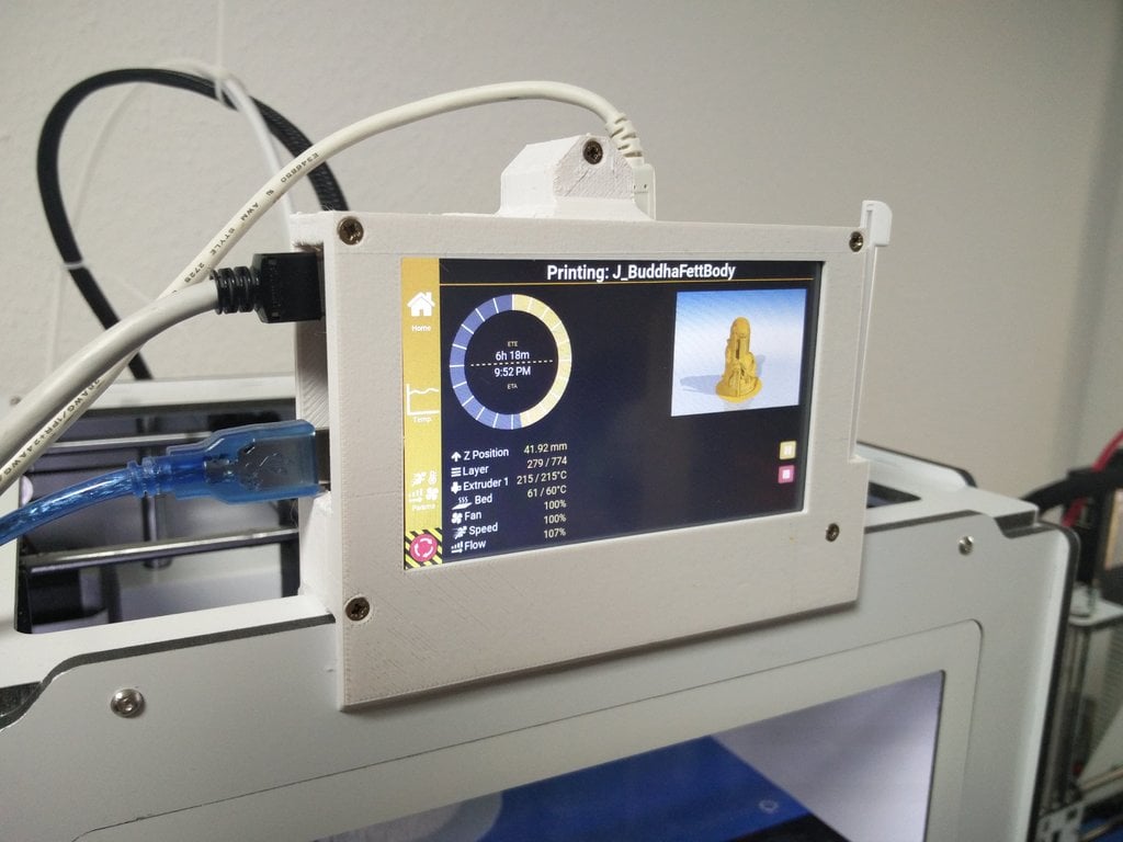 The perceived thickness of the laser beam limits the resolution. The perceived thickness of the line depends on the brightness of the point, which in turn depends on the reflectivity of the material of the model and the angle of incidence of the beam on the surface.
With the current laser beam extraction algorithm, reducing the line thickness due to better focusing or increasing the single threshold value will result in improved resolution for bright points and complete loss of information for darker ones.
Now we have a compromise that by limiting the resolution we get information about all points of the surface on which the laser beam fell. Potentially, for the Piclop scanner, you can write a program that, at high resolutions, will take several pictures with different exposures. However, this will increase the already not small scanning time with a resolution of 5 megapixels.
Aside from individual models with fine, subtle relief, a reasonable resolution for this scanner is 1.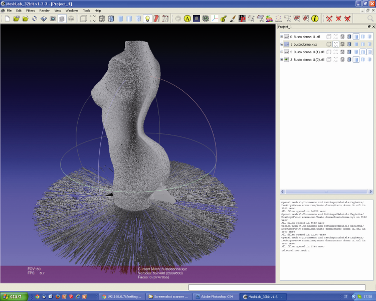 9 MP (1600 x 1200). At this resolution, the scanning speed for both scanners is about five minutes, but given the fewer final processing operations, the result from the Piclop scanner will be obtained a little faster.
I found it easier to achieve an acceptable result when scanning with two lasers on on a manually calibrated Piclop scanner. This is quite laborious, but patience and time allow you to achieve a result, while automatic calibration is a lottery, you may get lucky right away, you may never be lucky.
Follow author
Follow
Don't want
19
The OpenScan DIY 3D scanner works with Raspberry Pi, DSLR or smartphone cameras. — CNXSoft - Android Set-Top & Embedded Systems News
OpenScan is an open source homemade photogrammetry-based 3D scanner that works with Raspberry Pi camera modules, compatible ArduCam modules, as well as DSLR cameras or your smartphone camera.
After we wrote about the Creality CR-Scan Lizard 3D Scanner, an open source project caught our attention.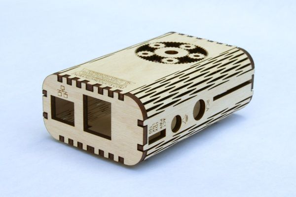 OpenScan kits include 3D printed parts such as gears, two stepper motors, a Raspberry Pi screen, and a Ringlight module for efficiently photographing a specific object from different angles.
The OpenScan Classic kit shown above allows you to scan 18x18x18 cm images and includes the following components: A4988
If you are going to use a Raspberry Pi as shown on the right side of the image, you will also need
- Raspberry Pi 3B+ SBC or compatible,
- 8MP Raspberry Pi Camera 8MP with 15cm ribbon cable (or compatible with e.g. Arducam 16MP)
- 1x Pi Shield (either pre-soldered or self-soldered) )
- 1x Pi Camera ring light (optional but highly recommended), pre-soldered or soldered by yourself
- 8xM3x8mm, 10xM3x12mm, 8x M3 nuts, 50x6mm steel rod, 2x 1m stepper motor cable
Alternatively, you can use a smartphone or a compatible ring-illuminated DSLR mounted on a tripod.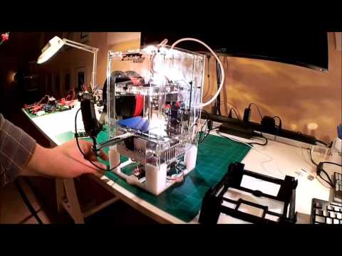 There used to be an Arduino kit, but it's outdated now.
An alternative design is the OpenScan Mini pictured above with a Raspberry Pi camera and a ring light suitable for scanning up to 8x8x8 cm.
The system will then take photos from different angles under the same lighting conditions thanks to the ring light. Depending on the complexity of the property, you may need to take hundreds of photographs. Photos can be imported into photogrammetry software for processing. Open source photogrammetry programs include VisualSFM, which is fast but only outputs point clouds, and Meshroom and Colmap with mesh and texture support, but both require a machine equipped with a CUDA capable GPU. Meshroom is the most popular and actively developing.
There is also OpenScanCloud, which will process photos in the cloud with minimal user intervention. It's free thanks to donations, but use is limited and whether it can stay operational may depend on continued support from donations.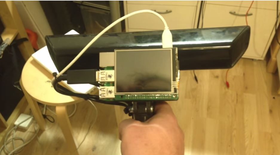 Here's a short demo of how it all works.
Find the latest Raspberry Pi Python software and custom Raspberry Pi OS image on Github, and Raspberry Pi scanner and screen 3D files on Thingiverse.
The easiest way to get started is to buy one of the kits directly from the project store for 107 euros and up. Please note that the complete kit with pre-soldered boards, Raspberry Pi 3B+ and Arducam 16MP camera module costs about 298 euros including VAT.
It is also possible to use photogrammetry without a kit, e.g. for larger objects, by simply photographing the object yourself, but the results can be mixed, as Build for Motorsport found out when comparing the CR-Scan Lizard 3D scanner to photogrammetry using only a DSLR camera . It should be noted that both methods also required editing the 3D model to remove "dirt" and adjust some of the shapes.