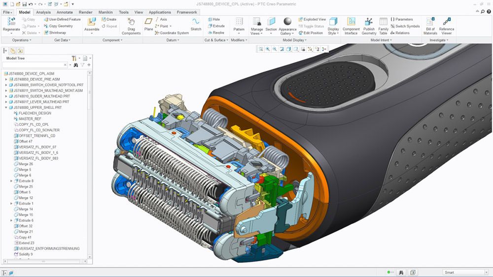
Plastic extrusion 3d printing
3D Printing Materials Guide: Plastics
Published on June 8, 2020 by Alexandrea P.
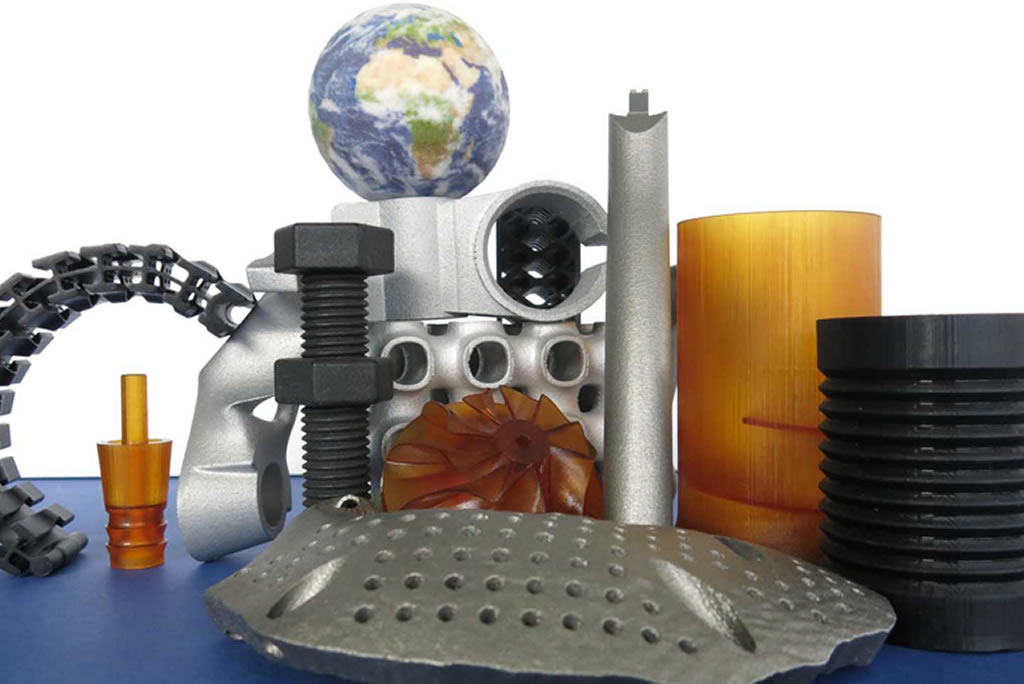
A plastic is a material made of synthetic or semi-synthetic compounds that has the property of being malleable (capable of changing its shape). Most plastics on the market are completely synthetic (most commonly derived from petrochemicals). However, given the growing environmental concern, plastics derived from renewable materials such as Polylactic Acid (PLA) are also popular on the market. Due to their low cost, ease of manufacture, versatility and water resistance, plastics are used in a multitude of products and sectors. In the AM sector, 3D printing plastics are also very popular.
In the following guide, we will take a look at the most common 3D printing plastics. As you may know, the most popular and affordable 3D printing process, FDM, produces parts through the extrusion of plastic filaments. However, the precision on FDM machines is not the same as other AM processes such as SLS or SLA. Plastics are often used with this technology to create prototypes. Therefore, for industrial and end-use parts, manufacturers might decide to opt for SLS (using plastic powders) or SLA (using plastic resins) technologies that offer more accuracy and part quality. Two other technologies that can print with plastics are Material Jetting and Multi Jet Fusion.
What plastics can be used in additive manufacturing? In filament or powder form, the plastic should melt to form the object you are printing layer by layer. In resin form, it should solidify to form the object. Each plastic will require different 3D printing parameters during the building process, and will give parts varying properties.
ABS
ABS filament is the most commonly used 3D printing plastics. It is used in the bodywork of cars, appliances, and mobile phone cases. It is a thermoplastic which contains a base of elastomers based on polybutadiene, making it more flexible, and resistant to shocks. ABS can also be found in powder form for powder bed processes such as SLS, and liquid form for SLA and PolyJet technologies.
ABS is used in 3D printing when heated between 230ºC and 260ºC. It is a tough material, able to easily withstand temperatures of -20ºC to 80ºC. In addition to its high strength, it is a reusable material and can be welded with chemical processes. However, ABS is not biodegradable and shrinks in contact with air, so the printing platform must be heated to prevent warping. Moreover, it is recommended to use a closed chamber 3D printer to limit particle emissions when printing with ABS. Learn more about ABS in our dedicated guide.
PLA
Known as polylactic acid, or PLA, this material has the benefit of being biodegradable, unlike ABS. PLA is manufactured using renewable raw materials such as corn starch. PLA is one of the easiest materials to print, though it does have a tendency to shrink slightly after 3D printing. You don’t require a heated platform when printing in PLA, unlike with ABS. PLA also prints at a lower temperature than ABS, between 190ºC to 230ºC.
PLA is a more difficult material to manipulate due to its high cooling and solidification speed. It is also important to mention that models can deteriorate when in contact with water. However, the material is consistent, simple to use, and comes in a wide variety of colors, making it suitable for FDM 3D printing. Learn more about PLA in our dedicated guide.
PLA 3D printing filament spools
ASA
ASA is a material that has similar properties to ABS, but has a greater resistance to UV rays. As with ABS, it is advised to print the material with a heated bed platform to prevent warping. When printing with ASA, similar print settings are used to ABS, but extra care must be taken to print with a closed chamber due to styrene emissions.
PET
Polyethylene terephthalate, or PET, is commonly seen in disposable plastic bottles. PET is the ideal filament for any pieces intended for contact with food. Moreover, the material is fairly rigid and has good chemical resistance. To obtain the best results when printing with PET, print between 75 – 90ºC. PET is commonly marketed as a translucent filament, with variants such as PETG, PETE, and PETT also sold. Advantages of PET include that the material doesn’t release any odours when printing, and is 100% recyclable.
PETG
PETG, or glycolized polyester, is a thermoplastic widely used in the additive manufacturing market, combining both the simplicity of PLA 3D printing and the strength of ABS. It is an amorphous plastic, which can be 100% recycled. It has the same chemical composition as polyethylene terephthalate, better known by its acronym PET. Glycol has been added to reduce its brittleness and therefore its fragility. Learn more about PETG in our dedicated guide.
Polycarbonate (PC)
Polycarbonate (PC) is a high strength material designed for engineering applications. The material has good temperature resistance, able to resist any physical deformation up to around 150ºC. However, PC is prone to absorbing moisture from the air, which can affect performance and printing resistance. Therefore, PC has to be stored in airtight containers. PC is highly valued by the AM industry for its strength and transparency. It has a much lower density than glass, making it particularly interesting for designing optical parts, protective screens or decorative objects. Learn more about PC in our dedicated guide.
A 3D printed part made from PC
High Performance Polymers (PEEK, PEKK, ULTEM)
The evolution of 3D printing technologies has led to extensive research work on printing materials, enabling the development of a whole range of high-performance filaments with mechanical characteristics similar to those of metals. There are several types of high-performance 3D printing plastics such as PEEK, PEKK or ULTEM – they are distinguished by family such as polyaryletherketones (PAEK) or polyetherimides (PEI). These filaments have a very high mechanical and thermal resistance, are very strong and at the same time much lighter than some metals. These properties make them very attractive in the aerospace, automotive and medical sectors.
Due to their characteristics, high performance polymers cannot be printed on all FDM machines on the market.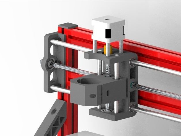 Indeed, the 3D printer must have a heating plate capable of reaching at least 230°C, an extrusion at 350°C and a closed chamber. Today, about 65% of these materials are printed with FDM technology, but they are also found in powder form, compatible with SLS technology. Learn more in our dedicated guides on PEEK and PEKK.
Image via VisionMiner
Polypropylene (PP)
Polypropylene is another thermoplastic widely used in the automotive sector, professional textiles sector, and in the manufacturing of hundreds of everyday objects. PP is known for its resistance to abrasion and its ability to absorb shocks, as well as relative rigidity and flexibility. However, drawbacks of the material include its low temperature resistance, and sensitivity to UV rays which can cause it to expand. Due to this, several manufacturers have developed alternative types of PP, simili-propilenos, that are stronger both physically and mechanically.
Nylon
Objects made from polyamides (nylon) are usually created from a fine, white, granular powder with SLS technology. There are however some variants of the material such as nylon that are also available in filaments used in fused deposition modeling (FDM). Due to its biocompatibility, polyamides can be used to create parts that come into contact with food (except foods that contain alcohol).
Constituted of semi crystalline structures, polyamides have a good balance of chemical and mechanical characteristics that offer good stability, rigidity, flexibility, and shock resistance. These advantages mean that the material has many applications across sectors and offers a high level of detail. Due to its high quality, polyamides are used in the manufacture of gears, parts for the aerospace market, automotive market, robotics, medical prostheses, and injection molds. You can learn more in our dedicated guide on Nylon.
Image via Sculpteo
Composites
Composites are extremely beneficial when making lightweight yet strong parts. The fibers add strength to a part without adding weight, which is why we also refer to composites as fiber reinforced materials.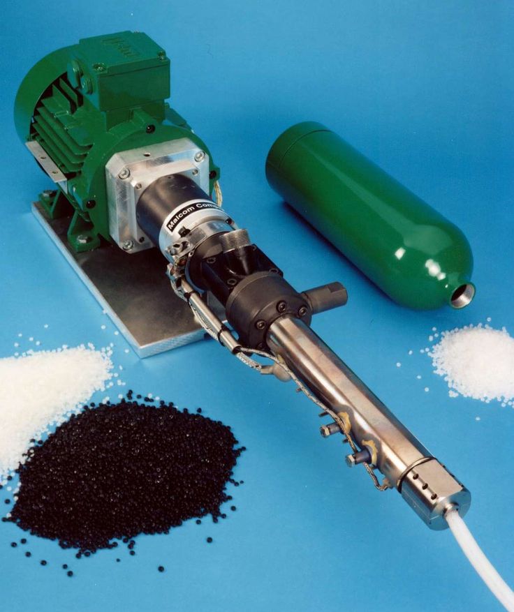 There are two types of reinforcements, short fiber or continuous fiber. In the first case, chopped fibers, which consist of segments less than a millimeter in length, are mixed into traditional 3D printing plastics to increase the stiffness and to a lesser extent the strength of components. Chopped fibers can be mixed with thermoplastics such as nylon, ABS or PLA.
Alternatively, the fibers can be added to the thermoplastics continuously to arrive at a stronger part. The main fiber used in the 3D printing sector is carbon fiber, but there are also other fibers such as glass fiber or Kevlar. You can find more information in our dedicated guide.
Carbon fiber reinforced filament spool
Hybrid Materials
There are a variety of hybrid materials that mix base plastics with powders to give them a new color, finish or additional material properties. Often based on PLA, these materials are usually made of 70% PLA and 30% hybrid material. For example, wood-based filaments ranging from bamboo, cork, wood dust, and more are available. These wood-based materials mixed with PLA give the hybrid filament a more organic texture. Additionally, some hybrid materials incorporate metal powders to work with FDM-based technologies, to give parts a metal finish. They can be based on copper, bronze, silver, and more.
3D filaments based on wood.
Alumide
Alumide plastic objects are manufactured from a combination of polyamides and aluminium powder using the SLS process. The material has a large, slightly porous surface and a gritty, grainy appearance offering great strength and good temperature resistance (up to 172°C). However, some post-processing treatments are necessary, such as grinding, sanding, coating, or milling.
Alumide is used for complex models, design pieces, or for small series production of functional models that need high rigidity and an appearance similar to aluminium. This technique involves few geometric limits.
Soluble Materials
Soluble materials are materials printed with the intention of being dissolved in a future stage of the manufacturing process. The two most common soluble filament materials are HIPS (High Impact Polystyrene) and PVA (Polyvinyl Acetate). HIPS is associated with ABS, and can be dissolved with limonene, whereas PVA is associated with PLA and can be dissolved using just water.
There are also BVOH filaments which are becoming increasingly popular, especially in dual extruder printers. This is because the material is soluble in water, and according to experts has a higher solubility than PVA.
Flexible Materials
A newer type of filament, and one of the most successful, are flexible filaments. They are similar to PLA, but usually made out of TPE or TPU. The advantage of using these filaments for 3D printing is they allow for the creation of deformable objects, widely used in the fashion industry. Generally, these flexible filaments have the same printing characteristics as PLA, though they come in a variety of ranges based on their stiffness. It is worth finding out which type of extruder is best suited to the material to avoid jams when 3D printing.
Flexible materials are widely used in fashion and design
Resins (for photopolymerization-based 3D printing)
3D printing technologies based on photopolymerization use UV-sensitive resins to create objects layer by layer. In other words, they use a light source such as a laser or LCD screen to solidify a liquid photopolymer. Technologies include SLA, DLP, and even Material Jetting (PolyJet). Creating parts using resins results in high detail and smooth surface objects, nevertheless, the color range is still quite limited using this process. What differentiates resins from FDM filaments is that it is impossible to mix resins to obtain different results quite easily.
Standard resin has properties similar to ABS: the surface finish of the part will be good given the photopolymerization process, however mechanical properties will be moderate. More advanced resins do exist for technical applications such as in dentistry (also need to be biocompatible), or engineering. Additionally, flexible resins that offer greater flexibility and deformation can be used to make jewelry. Over the years, manufacturers have expanded their range of liquid photopolymers to answer manufacturing needs from various sectors. Therefore, you should be able to find resins that have high-temperature resistance, can withstand large impacts, or that have high elongation properties.
The 3D printing resin is poured in a tank
What do you think of our explanation of these 3D printing plastics? Let us know in a comment below or on our Facebook and Twitter pages! Don’t forget to sign up for our free weekly Newsletter, with all the latest news in 3D printing delivered straight to your inbox!
JWELL Machinery 3D Printing Extrusion Production Line Supplier
- Home
- Products
- Extrusion Line
- Plastic Profile Extrusion Line
- 3D Printing Extrusion Production Line
Descripetion about 3D printing extrusion production line
Item | Specification |
Place of origin | China |
Brand name | JWELL |
Model number | JWS45/30 JWS30/28 |
Certification | CE ISO |
Minimum order quantity | 1 SET |
Packaging details | Wooden pallet packing |
Delivery time | 70days |
Payment terms | TT. |
 LC
LCSpecifications of 3D printing extrusion production Line
Model | JWS-PA-18 | JWS-PLA-3A | JWS-PLA-3B |
Material | ABS,PLA,TPU,PEEK,PLA,PVC,PE,EVA,PP,PC, PA | ||
Extruder specification | JWS45/30 | JWS30/28 | JWS45/30 |
Products (mm) | 3-18mm | 1-3mm | 1-3mm |
Speed (m/min) | 30m/min | 50m/min | 120m/min |
Power of main motor(KW) | 40KW | 25KW | 40KW |
3D printing extrusion production Line Application
3D printing supplies is an indispensable part of the 3D printer, and to some extent, it also affects the more wide range of 3D printing. Among them, engineering plastics is the most widely used materials for 3D printing consumables, such as ABS, PA, PC, PPSF, PEEK, etc., such as industrial parts, housing materials, can be sprayed, machined, plated.
Among them, engineering plastics is the most widely used materials for 3D printing supplies, such as ABS, PA, PC, PPSF, PEEK, etc., such as industrial parts, housing materials, sprayable, machining, electroplating Other bioplastics applications are also very broad, such as PLA, PBAT, PBS, PCL, and other degradable materials, including PLA, ie polylactic acid, he is the best material in printing materials, with a variety of translucent and gloss, The environment is very friendly. PCL materials have good biocompatibility, non-toxic, widely used in medical sectors, such as printing heart brackets, etc. We study 3D print consumables for many years, rich experience. If you want to buy 3d printer extruder from plastic profile extruder line at a good price, we can provide a variety of best equipment programs.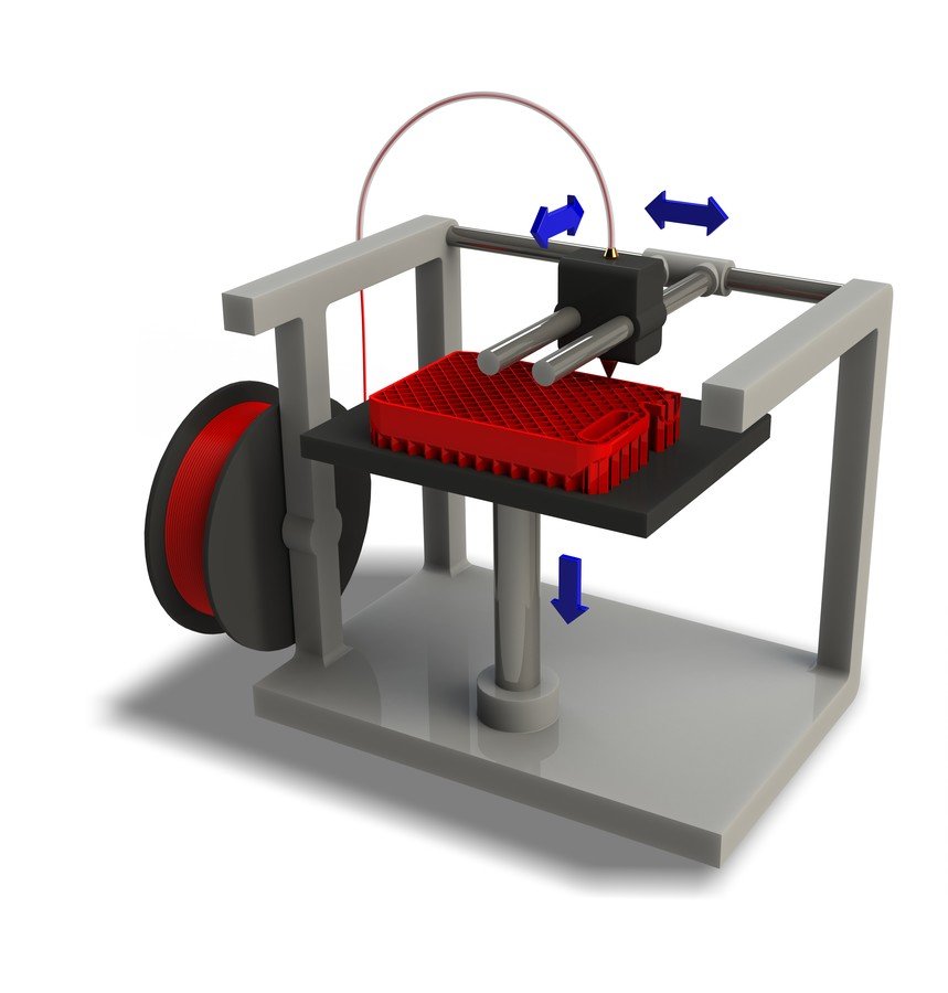
FAQ about 3D Printing Extrusion Production Line
What is the classification of 3D print consumables? +
3D printing consumables material is an important material foundation for 3D printing technology. Its performance has largely determines the comprehensive performance of shaped parts. So far, its consumables have been very rich, 3D print consumables can be divided into three major categories such as polymer materials, metal materials, ceramic materials.
Can 3D print consumable material recycled and reuse? +
Current production process still cannot use recycled raw materials
This production line can extrud out which materials? +
This extruder line is suitable for extrusion molding of PLA, ABS, PP, PC, TPU, PETG, PEEK, PVC, PE, EVA, etc.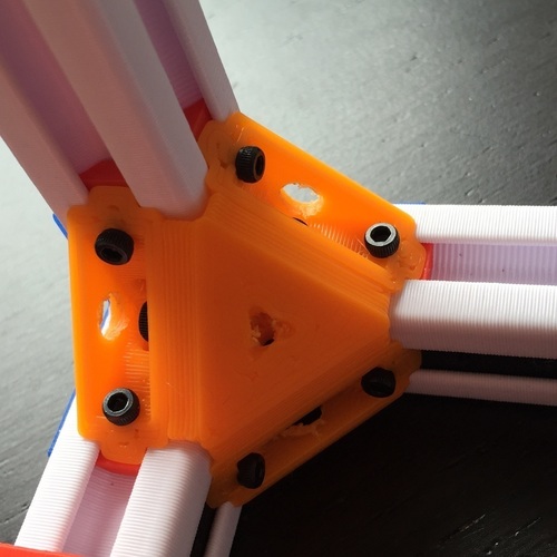
3D printing exrusion pruoduction line Performance and Advantages
Host pressure closed-loop control, linear closing loop control; fast adjustment speed, high linear accuracy;
2. the 3d printing extrusion production speed can reach 80-100 m / min; high efficiency, good stability;
3. run information online display, emergency shutdown protection; easy to operate, safe, and reliable.
4. The touch screen and Siemens controller are used, and the system has stable operation and high integration.
◆ Touch screen displays all operations pages such as extrusion unit, traction unit, winding unit, etc., can generate a "head material temperature-time" curve, "head pressure-time" curve, "wire diameter-time" curve
◆ Provide formula management functions, users only record and form a formulation of production parameters of various materials, saved in the touch screen, and the next regeneration can be called directly without resetting it.
5. Die extrusion stability, a variety of optional diameter
◆ precision machining an extrusion die, plasticizing effect, extrusion stability, a variety of optional diameter.
◆ The die heating employs the inlet thermocouple temperature, PID control, and the temperature deviation can be controlled at ± 1 ° C.
◆ With the high precision transmission system, the pressure closed loop control is used, and the extrusion pressure value and the target pressure value are ± 0.1 MPa.
6. Traction unit speed adjusts automatically to ensure stable diameter diameter
◆ The radiometer measures the line diameter in the line, real-time feedback line size, and the traction motor forms a wire-diameter ring control, the automatic adjustment speed, ensures that the wire diameter is stable, and the accuracy can reach ± 0.01 mm.
3D Printing Extrusion Production Line Packing & Shipping
Problem with extrusion? You are here / Habr
Do you know what a real universal fakap is? Recently, I fully felt it in my skin. I hope the text will be useful for novice 3D printers, since the problem is not an isolated one, but it was not easy to find a solution, and even I, an old atheist, almost believed in miracles.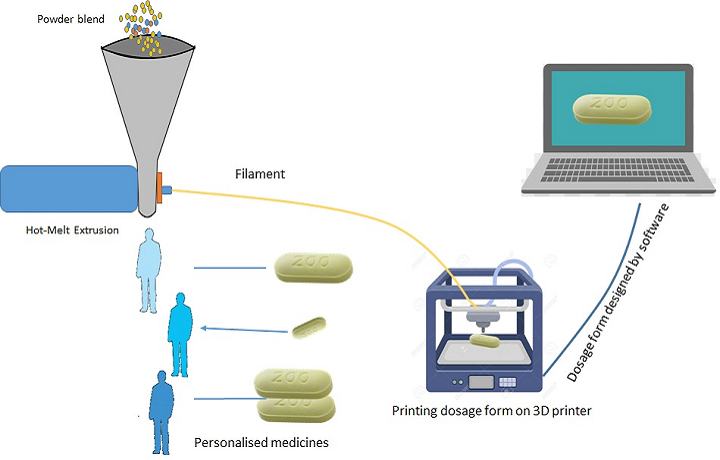 Forgive me for the presentation, since I am not a writer or a blogger, but a simple engineer - a firm engineer.
In addition, the text is intended for people with minimal experience with 3D printing.
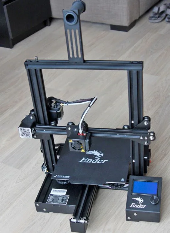
Solely for the reason not to inflate the article and not explain the purpose of various details and slang words. I'll start with the backstory. A little less than a year ago I bought myself an inexpensive 3D printer. One of the most popular (not as advertising, but to make it clear what it is about) is Ender 3. The assembly was simple, there are many recommendations on the Web. Of course, assembling it according to the instructions, I would have received a non-working unit, but after “smoking the manuals”, I managed to complete the first test print for 5 plus for such a simple machine! Everything was fine up to a certain point. But then it began ...
If you're interested, welcome.
For those who are too lazy to read:
The extruder pressure roller arm has broken.
The printer was needed for a specific task - printing non-standard cases for various small-scale electronic crafts. After I played enough with ready-made models and provided my daughter with various little animals and little men, I mastered FreeCAD “on top” and began to do useful things. Everything went well ... By and large, the print was launched "from the foot", set it and went to bed. Unless the first layer controlled. But the first "bells" appeared.
Somewhere part of the layer will fall out, somewhere the plastic will burn. I calibrated the table “according to a piece of paper”, sinned on the plastic and the nozzle, changed the settings in the slicer, plastics and nozzles - the problems disappeared. Bye…
At one "wonderful" moment, I ran into an "insoluble" problem. The end of March, a smooth transfer to a remote location (I successfully moved from the Moscow region to Minsk 2 years earlier), I decided to assemble a separate computer for work from what I had.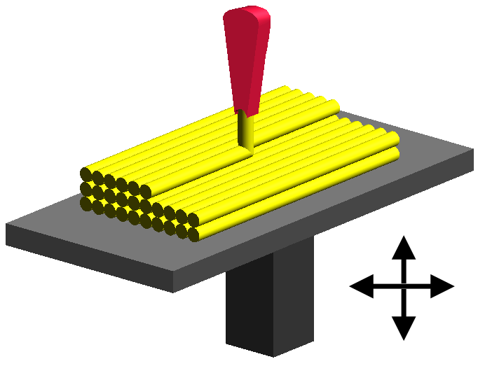 In the stash was a good motherboard, processor, a couple of monitors and 2 cases. One is a huge full-fledged ATX, the other is a barebone. I decided to collect in a small one, so that it takes up less space. The case is non-standard. With cradle for 1 CD drive and 3.5 inch hard drive. I found 3x 2.5 SATA SSD of small volume, for the system and one is enough "more than" and 1x for 1Tb 2.5 HDD.
All this "living creatures" was placed in a large building on a makeshift adapter from old bank cards. But, since a printer has already appeared, it would be nice to use it. I created a holder model, put it on print and went about my business. When I looked at how it prints, I saw only noodles ... From that moment on, the path of repair went, 2 months long. I will try to paint on the shelves, what helped and what did not, and what was the root cause.
Step 1 Adjusting the rollers {prevention is always good}
Once again, I set up the table “on a piece of paper”, launched it - the plastic does not stick. I changed the settings, plastics - without result. Instead of sticking to the table, it bends onto the nozzle. When I rechecked the nozzle gap settings, I found that the rollers were loose and the table had play by almost 5mm at the edges. It's strange how he used to print at all before ... It seemed that the reason was found. Adjusted. But it didn't get any better. With grief in half I printed the part, but the quality left much to be desired:
Obvious gaps in print are visible.
And here are the bundles…
Step 2. Song of Ze[l]de {not bad when everything goes like clockwork}
The first thing that came to my mind was the problem in the Z-axis drive. And all the advice on the forums on a problem similar to mine pointed to this. Took it apart and checked for smoothness. The nut bit the thread a little and found a “bug” in a couple of rollers. When moving without the drive screw, the "X" rail stuck a little for 1 turn of the roller. I ordered a drive nut, rollers (spare parts are always good, but that was not the point). Using the method of combinatorics and some kind of mother, I distributed the axle rollers according to the loads so that the defective ones had minimal effort. The "bite" is gone. Cleaned and lubricated the drive screw. Adjusted the position of his engine. As a result, a light touch of a finger is enough to lower the carriage down. The result is negative.
Step 3. Slicer {tuning, but not solving the problem}
Updated slicer. Moreover, the new release just had an improvement related specifically to the print quality for my printer. Played around with flow and speed, layer thicknesses, etc. Even successfully printed some simple small cases and parts. But the settings were frankly wild: flow - + 10%, speed - -5%. Considering that after assembly, excellent printing was obtained at the “default” settings. The problem of printing complex parts has not disappeared .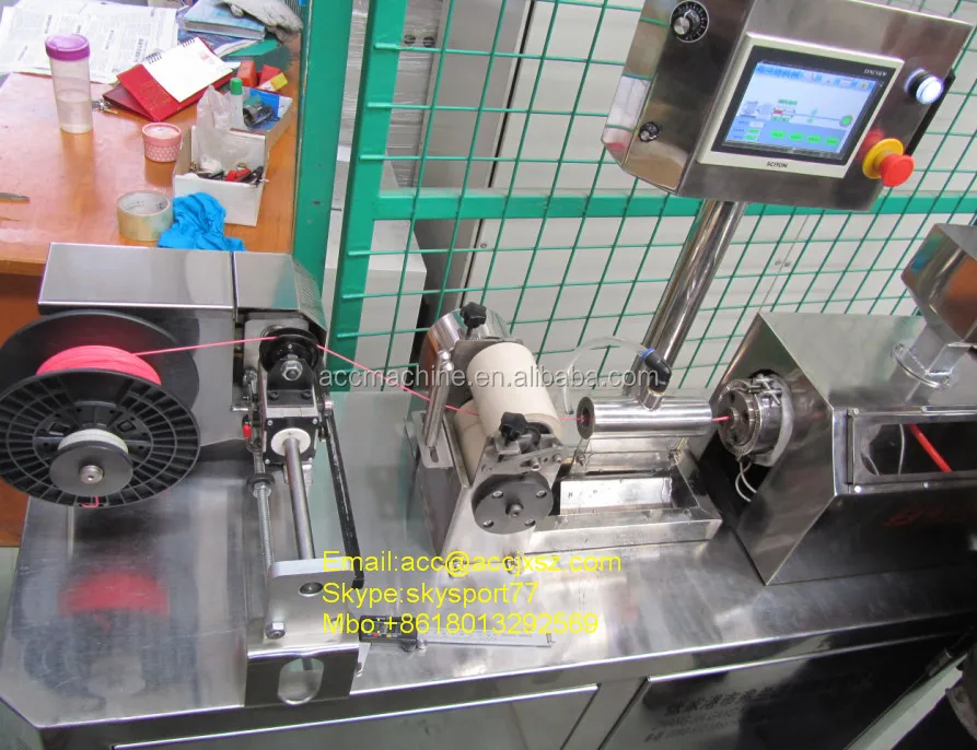 ..
..
Based on this article: https://habr.com/ru/post/494058/ I made a brushing timer for my daughter. I am preparing a separate description for it. Spoiler: eight-legged controller, firmware - 119 assembler commands.
Step 3. Extruder {and happiness was so close...}
Logic dictates that since there are no problems with the geometry and drives of the axes, there must be something with the feed. Removed the filament feed gear and cleaned it. No visible wear is observed. I returned it to its place, slightly shifting along the flight, to even out wear. The result is 0. Eh, if I look a little to the right, I would save a month of nerves and $ 200.
Step 4. Checking the SD drivers {no comment}
Excellent geometry, no problems with the mechanics. At the time of the first assembly, everything was much worse. A bunch of studied materials, improvements and settings, and the result is zero. I do not believe in miracles, electronics remained. Moreover, members of the forum often complain about burnt drivers. It is clear that a completely burnt out shoulder of the bridge can be detected “by eye” immediately, I thought about a “floating” malfunction. After all, the plastic lays down normally, then - passes, the thread becomes thinner, hair and other charms. I ordered an improved control board on ARM, but in order not to waste time, I decided to check the existing one. I removed the board, the Z-axis motor as an inductive load, assembled the stand on the table, set the temperature of the hot end with a resistor so that the extruder could be rotated. I looked at the waveforms on the SD coils. Everything is fine. He warmed the driver with a hairdryer (a crystal defect or unwelding sometimes manifests itself), mechanically acted on the driver IC, cooled propane with butane (gas for lighters). Note. It cools quite well to -20, it is not necessary to buy an expensive freezer for this.
Everything is fine. Failures are not visible!
Step 5. Updating the firmware {and I almost believed in a miracle and conspiracy theory}
No, I am sure that miracles do not happen. There are bugs, glitches, tricks, lack of information, subjective perception of reality, after all. But not miracles! But how to explain that, with good mechanics and electronics, printing behaves extremely strangely? The Chinese made a bookmark in FW in order to additionally barry with boards? It is done elementarily, but, I think, they would have been discovered long ago and a white fluffy fox would have come to the trademark. Bug in the firmware? Everything is possible, only somehow it manifested itself strangely.
EEPROM settings wrong or FLASH* "bugging"? Most likely. Okay, since the board is on the table, nothing prevents it from being reflashed. Updated to "vanilla" Marlin 1.1.9, collected everything back. The result is that the miracle did not happen.
*Purely theoretical substantiation of the possibility of connection of the problem with FLASH memory:
Let's say we have the following code fragment:
…
const uint8_t step = 0x18;
…
position += step;
…
At each iteration, the “step” setting is added to the current position. Since the program is executed on a microcontroller (MK), the code and constants are placed in ROM and can only be changed during an external programming procedure (we will omit the possibility of reprogramming the FLASH memory by internal means of the MK). This procedure is performed once by the manufacturer. Now 2 important points: the controller processor reads commands and constants from ROM every time, forget about caches, Atmega does not have them. That is, if the loop went through 1000000 iterations, then the constant was read the same million times. With each read, FLASH degrades a little. I don’t know what the critical reading threshold for NOR is, I think it’s tens of billions, but TLC NAND already degrades quite well after 10-20K readings . .. The second point is not the fact that our narrow-eyed friends did not use rejected controllers. I actually got one like this. PICs. Not soldered, but there are strange marks on the case. FLASH was not erased, at 3.6V they did not want to be erased or flashed. I had to raise it to 5V, after which the recording / verification began to take place. Let's say our constant was written to a defective cell. While the device is new, 0x18 was read stably. But from time to time (and for Atmega, the guaranteed time for saving data is not the longest) and degradation, at some point it began to read not 0x18, but 0x08. Not every time, but still. I know, rather than degrading 1 to 0, but vice versa, this is just an example. So, as long as the correct number is read stably, the movement occurs correctly, but when failures occur, an incorrect setpoint is added to the result, which leads to feed failures. This is the simplest and most unlikely example. There may be other glitches, for example, in the addition command, the source of R6 will change to R7.
The assembler instruction remains valid, the processor will execute it, but the result will be incorrect ...
Step 6. Flush the “throat” {keep your head cool and the hot end clean, I recommend doing this immediately after buying a printer}
A gift from "heaven" was a link on one of the forums to a video from the manufacturer. There they honestly admit that not all hotends are equally useful, that is, they are well assembled.
Teflon tube not fully pressed in, cut uneven. The consequence is the formation of a cork and the extruder cannot normally advance the plastic. Here it is - my case!
Abnormal flow and retract values, everything converges. Despite late Saturday evening and a visit to a brasserie, I decided to check it out. Exactly. Guana is unmeasured there, right down to the remnants of the plastic that I used to print a month ago (the same green holder). Very likely to win! I cleared the “throat”, cut the tube evenly, pressed it in as far as it would go, also fixed the second end of the tube more tightly, many people use electrical tape, but I wound a little 0. 7 wire, which allows you to freely unscrew the holder:
And here is the “killed” end of the tube, you can see that it was cut crooked:
The model is cut into layers with default settings. The seal ... The border went, the contour went, there is no snot during the retract. Hooray!!! Victory!!! I was about to write an article so that others would not suffer, but ... A complete fiasco. Thinning and tearing of plastic, gaps in printing. Already ready to give up. The wife encourages, but you throw it away, buy a new one! I can't do that. There must be a reason. That's just where??? There were no more reasonable (and censored) thoughts ...
Remark about cleaning the “throat”:
All operations with the hot end are done only “hot”, otherwise there is a chance to break everything. After warming up, the first step is to remove the nozzle and clean it from the remnants of the “cork”. I did this by heating the nozzle on a gas stove flame and carefully removing the plastic. Didn't clean the inside. Then, also on a heated hot end, the tube clamp is unscrewed. He can only move up. After retracting the latch, the tube should be gently but with force removed from the “throat”. We remove all the latches, since the damaged end still cannot be saved, carefully, back and forth, we clean out all the dirt, constantly removing it from the tube. As a result, the tube should easily pass through the throat through and through. The assembly was performed by the FIFO sequence. First, I installed the nozzle, then the tube clamp in the hot end, but did not tighten it completely, leaving about 1 turn. The worn part of the tube is cut off at a right angle and inserted into the throat as far as it will go. After that, the holder is tightened and the second one is installed, on the opposite side of the "teflon".
Step 7. Feed Calibration {with good mechanics, most likely not needed unless after replacement of drive parts or flashing}
In the instructions for upgrading to the "vanilla" Marlin, it was said that for the factory printer all settings are ideal, but the accuracy of the plastic feed may be slightly off. Okay, let's calibrate. He pulled out the plastic, warmed up the hot end (there is a lock in the firmware, it does not allow you to move “E” to a cold one). I unscrewed the tube from the feed mechanism, cut the plastic flush and executed the 300mm extrusion command. I have a ruler at 350. Extrusion lasts long enough, upon completion, I measured the length of the released filament and could not believe my eyes 226mm. I understand the difference of 3-5%, but not 25%! I'll try another plastic...
Note. I saw how the feed is regulated according to the marks on the bar marked with a marker, But with cutting, IHMO, more precisely.
Preparation for test extrusion:
After extrusion:
We measure with a ruler, in my case (after repair) it turned out 292mm. Next, go to the menu: control / motion / step mm, see how many steps per mm are set for the extruder. In my case it is 93. Let's do a simple calculation:
>>> (300*93)/292
95.54794520547945
Change the setting and save the setting. Re-extrusion - error at the measurement level.
Step 8. Victory!
At first I checked for PETG, I decided to change to PLA. The first one I overheated a little during drying, I attributed the inadequate spread to possible sticking on the coil. Cutting, extrusion. And nothing. Plastic is not supplied at all. The axis of the drive rotates slowly, but the screws show that there is movement. I looked, the bar did not lie correctly between the gear and the pressure roller. Okay, I'm correct. That the roller dangles a little. Gotta pull it up. And fig! Here he is the culprit of all my troubles:
The pressure roller arm is cracked. At the same time, the clamping force remained sufficient for partial advancement of the rod. Gear marks remained and the pressure roller rotated.
Accordingly, all games with the pressure spring setting were unsuccessful. The slips of the bar were invisible to the eye, and the crack could not be seen on the assembled mechanism. All! Engineer's ecstasy received! The lever was glued together, an aluminum mechanism was ordered, a spare was printed just in case (if it breaks while I wait for a new one). Here is a link to the model. Of course, it’s unpleasant to spend so much time and money over such a trifle, but it helped me dive much deeper into the processes of printing and catching glitches.
Actually, the first part after repair. Clamping lever:
Finally, my presence sensor found a "face". The case was printed even before the breakdown:
Attempts to print a “face” on a faulty printer (after cleaning the “throat”):
I hope this material will help at least someone not to make so many stupid attempts to find a primitive malfunction and save money. Of course, I did not deal with the problem every evening, but in total - a day, probably, was spent. For the money - about $ 200 for parts. The price of troubleshooting is 15 minutes and a couple of drops of "superglue". It's a shame? Rather not, because the experience and spare parts will remain with me!
Smooth printing and excellent adhesion everyone!
23 Steps to Victory (Manual and Guide)
Uh, There was such a post:
-their-elimination-fro/ “Typical print quality problems and methods for their elimination from Simplify3D on October 30, 2015 from Author: Pashka_Khv”
At the request of the people of 3 DTODAY, I begin the translation of this guide, which will be further possibly supplemented.
Print Quality Troubleshooting Guide – (off-line version by ski)
Copyright © 2015 Simplify3D, All rights reserved.
UnAuthorized Translation © 20151101 [email protected]. No rights reserved.
https://www.simplify3d.com/support/print-quality-troubleshooting/
IMHO - 3D Maker's Bible, 3D Rake Minesweeper, etc. and so on.
WARNING: HUMOR INTRODUCED by small text and second filament of story. ..
So,
... I’ll start my substitute from the end:
23 steps to victory,
Manual for the APPLIASE 3 D -print, and
-the allowance for eliminating faults
23.0. Uneven Extrusion ~ The Extrusion Volume is generally a constant value and not uniform enough to reproduce an exact shape.
In order for your printer to be able to create precise parts, it must be able to extrude a very constant amount/volume of plastic.
If this extrusion changes in different parts of your print, it will affect the final print quality.
An extrusion inconsistency can usually be identified by observing the printer up close as it prints.
For example, if the printer prints a straight line, 20 mm long, but you notice that the extrusion seems to be rather bumpy/bumpy, or seems to vary in size, then you are likely to experience this problem.
We have summarized the most common causes of intermittent extrusions and explained how each can be solved.
23.1. The thread is stuck or tangled;
The first thing you should check is the spool of plastic filament you have chosen that is fed into your 3D printer.
You must make sure that this spool is free to rotate and that the plastic can be easily rolled up, dropped and unwound from the spool.
If the filament becomes tangled or the spool has too much resistance to free rotation, this will affect how evenly the filament will be extruded (=extruded) through the nozzle.
If your printer is equipped with a Bowden-style filament feed tube (a small hollow tube through which the filament is threaded), you should also check to make sure that the filament can move easily through this tube without too much resistance.
If the tubing is very resistant to filament, you can try cleaning it or applying some lubricant to the inside of the tubing, sanding all transitions and pushfits to a mirror finish.
23.2. clogged extruder;
If the filament is not tangled and can be easily pulled into the extruder, then the next thing to check is the nozzle itself.
It is possible that there are some small debris or foreign plastic inside the nozzle that may interfere with normal extrusion.
The easiest way to check this is to use the printer engine's virtual control panel in Simplify3D to "manually" push some plastic out of the printer's nozzle.
Watch to make sure the plastic is being extruded evenly and consistently.
If you notice a problematic oddity, you may need to clean the nozzle. Please contact the manufacturer (or the corresponding 3Dtoday.ru forum) for instructions on how to properly clean the inside of your nozzle.
23.3. Very low layer height ;
If the filament spins off the spool freely and the extruder is not clogged, it may be helpful to check a few parameters in the Simplify3D software.
For example, if you are trying to print at an extremely low layer height, such as 0.01 mm, there is very little room for plastic to leave the nozzle.
This gap is only 0. 01 mm high (under the nozzle) and means that the plastic can be very difficult to exit the extruder towards the nozzle (there is mechanical resistance = obstruction at the exit of the nozzle).
Double check to be sure you are using a reasonably calculated/selected layer height for your printer to print.
You can view this setting by clicking on “Edit Process Settings” and selecting the “Layer” tab.
If you are printing at a very low layer height, try increasing this amount/value to see if the problem goes away.
23.4. Incorrect extrusion width;
Another parameter to check in Simplify3D is the extrusion width you specified for your extruder.
You can find this setting by clicking on the “Edit Process Settings” button and going to the “Extruder” tab.
Each extruder can have its own unique extrusion width, so make sure you select the correct extruder from the list (located on the left side of the screen) to check the settings for THAT SPECIFIC extruder.
If the extrusion width is significantly smaller than your nozzle diameter, this can cause problems when extruding plastic.
As a general rule, the extrusion width should be 100-150% of the nozzle diameter.
If the extrusion width is much smaller than the nozzle diameter (for example, 0.2mm extrusion width for a 0.4mm nozzle), then your extruder will not be able to push out a uniform melt flow of the filament filament.
23.5. Poor thread quality;
One of the most common causes of uneven extrusion that we haven't mentioned yet is the quality of the filament you are printing with.
Low quality filament may contain additional additives/additives that affect the consistency/composition of the plastic.
Others may have varying filament diameter which will also cause uneven extrusion.
Finally, many plastics tend to degrade over time.
For example, PLA tends to absorb moisture from the air, and over time, this can degrade print quality.