Minolta scanner 3d
[PDF] Introducing Konica Minolta s VIVID Line of 3D Scanners
1 Introducing Konica Minolta s VIVID Line of 3D Scanners The versatile Vivid line of 3D scanners is the product of choic...
Introducing Konica Minolta’s VIVID Line of 3D Scanners The versatile Vivid line of 3D scanners is the product of choice for a wide variety of applications. Each model in the line features camera-like easeof-use, portability, fast scanning time and an unequaled level of priceperformance. Konica Minolta’s Polygon Editing Tool (PET) software is included with each scanner so you can begin creating useful models as soon as you open the box. Konica Minolta is the world’s largest provider of 3D scanning solutions with customers using our products in a wide variety of industries. The list of applications increases every day. • • • • • • • • • • • •
Reverse Engineering Surface Inspection Medical – Hearing Aids, Prosthetic and Orthotic Manufacturing Dental – Orthodontic Appliances Rapid Prototyping Research Applications – FEA Modeling Input. Architectural Applications Forensic Modeling Archaeological / Anthropological Entertainment, Object & Character Modeling E-Commerce / Web Content Sculpture / Jewelry Design & Manufacture
VIVID Line – Features and Benefits Each model in the VIVID line offers outstanding benefits…
Feature Portable
VIVID 9i
VIVID 910
VIVID 910FW
Take your measurement system on the road. Weighing in at 31 lbs. The 9i provides a highly accurate mobile measurement system. The SCSI port allows data to be viewed instantly from a laptop computer.
Incorporates viewfinder and Flash RAM data storage. This gives you the freedom to take scan data without having to bring along your workstation.
At 25 lbs. The VIVID 910 FW has a viewfinder and a quick release base unit. Industry standard photographic tripods can support the scanner. The Vivid can be oriented in any position required for optimal scanning. Both desktop and tripod stands are available as optional accessories.
Fast Scan Time
Easy To Use
Versatile
Color Texture Maps
Utility Software Features
The 9i allows the user total control of scan time and data quality. Scanning times range from 2.5 seconds to 11 seconds per image.
Offers two scanning modes, enabling it to capture 76,800 data points in 0.5 seconds (Fast Mode) or 307,200 points in 2.5 seconds. (High Resolution Mode)
By collecting 75,000 data points in just 0.3 seconds, the VIVID 910 FW scanner is ideal for human subjects, eliminating the blur caused by movement. The class I laser is completely eye-safe!
The VIVID 9i has been integrated into the most advanced Inspection and Reverse Engineering Software Packages. This allows the user to complete their task in a single application. Three interchangeable lenses and photogrametric scan alignment allow the 9i to maintain accuracy on models ranging from teeth to tractors.
The VIVID 910 scanner is the only inspection scanner with the ease of use of a digital camera. No field calibration required.
Aim and shoot. The VIVID 910 FW is factory calibrated to maintain Accuracy. (Just like the more expensive 910.) No field calibration is required for great results.
Three detachable lenses provide all the flexibility you need to scan entire cars or just the hood ornaments.
With a single lens the 910 FW can capture scan areas from 36X27 up to 910 FW120 cm. The subject can be located from 0.6 to 2.5 meters form the scanner.
Are most accurate scanner also provides the best color data at 640 X 480 pixels per scan.
Color data is collected at 640 X 480 pixels per scan. These images can be combined for Vivid full-color 3D models.
The VIVID 910 FW utilizes a single lens system to capture texture map images with zero parallax. Full color and B/W images are supported.
All of the VIVID scanners include Konica Minolta’s own polygon editing software suite that allows the user to register (align) and merge multiple scans (both geometry and color data), fill holes, smooth surfaces and export the data to various formats. Installation and training on the software is included with the 9i & 910 packages. Konica Minolta’s new Easy Align Tool (EAT) software utilizes color targets to automatically align scan data as it is taken!
VIVID Line – Specifications by Model VIVID scanners offer the highest performance for their price range… Specification
VIVID 9i
VIVID 910
VIVID 910 FW
Range Resolution (Z-Depth)
0.03mm at highest resolution
0.05mm at highest resolution
0.336 mm at highest resolution (600mm to object.)
Resolution (X&Y)
0.145mm at highest resolution
0.175mm at highest resolution
1.12 mm at highest resolution
Data Points per Scan
307,200
307,200
76,000
Scan Time
User Controlled Fast – 0.3 Sec. Precision – 2.5 Sec. D. R. M. – 11 Sec. 8mm, 14mm and 25mm lenses included
Dual Mode: Fast – 0.5 Sec. Precision – 2.5 Sec.
0.3 Seconds
8mm, 14.5mm and 25.5mm lenses included
8mm Wide-Angle Lens
On-Board Data Storage
Not Available
Not Available
View Finder
5. 7” Color LCD Display
Up to 1GB using Flash Ram and PCMCIA adapter (Optional) 5.7” Color LCD Display
Distance to Object
0.5m to 2.5m
0.6m to 2.5m
0.6m to 2.5m
Field of View (FOV per scan)
93mm X 69mm up to 1750mm X 1121mm
111mm X 84mm up to 1300mm X 1100mm
Color Resolution (Per Scan) Safety
640 X 480 Pixels
640 X 480 Pixels
360mm X 270mm up to 900mmX1200m m 640 X 480 Pixels
Class 1 Laser (FDA) Eye Safe.
Class 1 Laser (FDA) Eye Safe.
Power
100 – 240 VAC 50 – 60 Hz Auto Switching
100 – 240 VAC 50 – 60 Hz Auto Switching
Reliability
With over 1500 units in use world-wide, the VIVID line of 3D scanners has been proven the most reliable in the industry. Produced in compliance with ISO 9001 quality standards.
Optics
5.7” Color LCD Display
Class 1 Laser (FDA) Eye Safe. 100 – 240 VAC 50 – 60 Hz Auto Switching
VIVID Line – Standard Accessories • • • • • • • • •
One-Year Warranty All Models o Protect your investment Interchangeable Lenses (wide angle, mid, telephoto) Vivid 9i & 910 o Increased Versatility Instruction Manuals All Models 6-Foot SCSI Cable (50 to 50 Pin) All Models Konica Minolta’s Polygon Editing Tool Utility Software All Models o Capture, Create and Export your Models 6-Foot Power Cord All Models White Balance Filter All Models o For Improved Color Fidelity VIVID Tripod w/ Pan/Tilt Head Vivid 9i & 910 Field Calibration System Vivid 9i o Maintain Highest Accuracy
VIVID Line – Optional Accessories • Photogrammetric Scan Alignment System (9i Only) o Maintain Accuracy on Large Parts • Rotary Stage / Turntable o Automate the scanning process • VIVID Tripod w/ Pan/Tilt Head o Flexible and portable • Tripod Dolly w/ locking casters o Most useful for large object scanning • VIVID Memory Card (910 only) o Take scan data without a PC • Travel Case w/ Wheels o Safe transport for mobile users • ENSIGN Frame Set o Automated inspection fixture
Photogrametric Scan Alignment System
Ensign – Automated Inspection Fixture.
VIVID Line – The Total Solution Konica Minolta has cultivated many partnerships in the scanning software industry in order to provide our customers with affordable, high-quality solutions. Many of the most popular applications for inspection, reverse engineering and content development will directly import the native scan file format of the Vivid scanners. Several applications have developed direct interfaces to the scanners, enabling the user to remain in a single application to complete a given task. This type of integration vastly improves the ease-of-use of the system and reduces the learning curve for the novice user. For applications that will not directly import the VIVID data, the Polygon Editing Tool software will export a number of industry standard formats. These include: *.STL, *.HRC, *.OBJ, *.DXF, ASCII, VRML 2.0, MGF Both geometry data and texture maps can be exported to file formats that support them. IGES surfaces and other CAD data formats can be obtained by utilizing a reverse engineering application.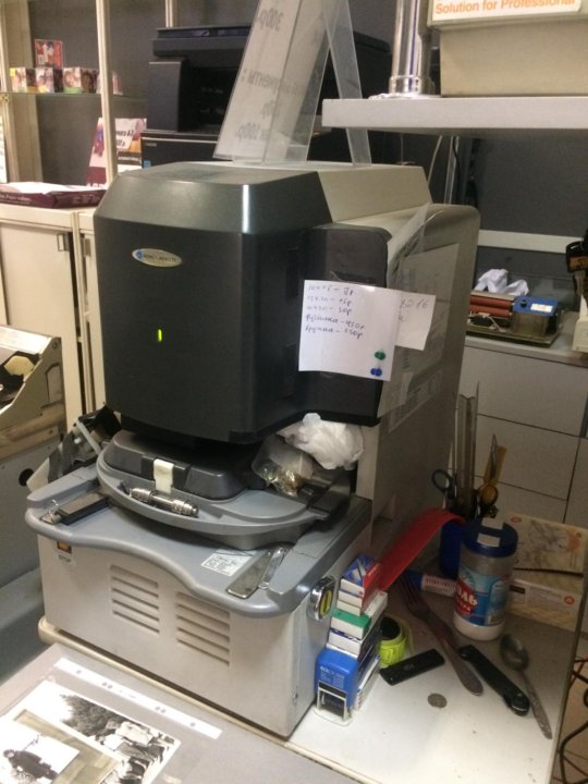
Software such as Innovmetric’s Polyworks combine with the VIVID 9i for a powerful inspection solution.
VIVID Line – Pricing The price of a complete Vivid system will depend on the specific accessories and software required for your application. Approximate pricing for several system configurations are shown below. Please contact your Konica Minolta sales representative for a formal quotation.
System Description
List Price
VIVID 910 FW System – Basic Package • VIVD 910 FW Digitizer • Konica Minolta’s Polygon Editing Tool Software • 6-Foot SCSI Cable (M 50 to M 50 Pin)
$23,800
VIVID 910 FW System “Crystal–Faces” Package • VIVID 910 FW Digitizer • Konica Minolta’s Crystal Studio Software • Cabling and Tripod w/ Pan Tilt Head
$29,995
VIVID 910 System – Basic Package • Vivid 910 Digitizer
$44,000
VIVID 910 System – Reverse Engineering Pkg. $65,800 • VIVID 910 Digitizer • Assembled Rotary Stage • Tripod w/ Pan/Tilt Head and Cabling • Advanced Polygon Modeling Package* • Advanced scan to IGES surfaces (NURBS) modeling* VIVID 9i System – R. E. and Inspection Pkg. $75,260 • VIVID 9i Digitizer • Tripod w/ Pan/Tilt Head and Cabling • Advanced Polygon Modeling Package* • Advanced scan to IGES surfaces (NURBS) modeling* • Scan to CAD (or Scan to Poly) Inspection software* VIVID Photogrammetric Scan Alignment Pkg. • Camera, Scale Bars, Targets and Software
$27,500
Although the list pricing for the VIVID scanners is the lowest you will find for laser scanners of this quality, if yours’ is a teaching institution, you may be eligible for Konica Minolta's educational discount. Please ask your Konica Minolta representative for details. * Price depends on software package included. Please consult your Konica Minolta representative regarding the software package best suited to your application.
Konica Minolta introduces Non-Contact 3D Digitizer RANGE7
KONICA MINOLTA RANGE7, a Non-Contact 3D Digitizer with 40µm accuracy and the high reliability required for industrial applications
Konica Minolta Sensing, Inc. (Hiroshi Furukawa, President; hereinafter referred to as “Konica Minolta”) is proud to introduce the Non-Contact 3D Digitizer Range7, a high-accuracy instrument for measuring the three-dimensional shape of subjects such as forged or cast parts, press-formed parts, plastic parts, etc.
| Product: | Non-Contact 3D Digitizer KONICA MINOLTA RANGE7 |
| Start of sales: | Planned for latter half of March, 2008 |
3D digitizers are equipment that perform the work of scanning a physical object (such as a part, mockup, etc.) to obtain three-dimensional data and uploading that data to a computer.
In 1997, Konica Minolta introduced the VIVID 700 (known as VI 700 in Europe), a compact camera-type non-contact 3D digitizer that utilizes laser light for non-contact instantaneous measurements of the three-dimensional shape of objects. Since then we have led the non-contact 3D digitizer market with the introduction of the popularly-priced VIVID 300 (VI 300) and the VIVID 900/910 (VI 900/910) for diverse industrial applications as well as measurements of cultural artifacts and the human body. Further, in 2004 the high-accuracy VIVID 9i (VI-9i) was added to the lineup and has been evaluated highly in the R&D and manufacturing areas of for industries involved with cast or forged parts, press-formed parts, molded parts, and mold or die manufacturing.
With the recent spread of 3D CAD, it has become common to exchange information and specifications in terms of 3D data rather than on the previous drawings basis. Further, along with the need for high-level quality control in manufacturing, there are also demands for catching and solving problems at an early stage in the development and initial manufacture of parts and products. Against this background, the market for non-contact 3D digitizers has expanded rapidly from being centered on the automotive industry to a wide variety of manufacturing fields, and this has been accompanied by increasing demands for higher accuracy and reliability.
The new KONICA MINOLTA RANGE7 continues the VIVID (VI) concept as the first product of a new series of high-performance instruments to meet the needs of the market. It utilizes a 1.31 megapixel CMOS sensor and provides the highest level of guaranteed accuracy1 for a non-contact camera type digitizer: ±40µm in ball bar2 accuracy evaluation according to VDI/VDE 26343.
1 Accuracy: Measuring instrument accuracy expressing the error limits under defined conditions.
2 Ball bar: Equipment for evaluation of accuracy, consisting of a bar to which balls have been attached to both ends.
3 VDI/VDE 2634: Optical 3D Measurement Systems testing guidelines issued by Germany in 2002.
The employment of testing methods utilizing ball bars is planned to be included in the proposed Japanese Industrial Standards related to the testing of CMM (coordinate measuring machines: equipment that measures three-dimensional coordinates by contact or non-contact methods) which are currently in the process of being defined. For the industry pioneer RANGE7, Konica Minolta has introduced testing using a ball bar calibrated by AIST based on VDI/VDE 2634 Part 2, one of the strictest standards. This testing is performed for all RANGE7 units. In this way, high reliability is ensured for manufacturing areas (particularly those requiring high accuracy such as reverse engineering from development to prototype stage or verification that the produced object matches engineering drawings) in a variety mechanical processed parts fields including general forming such as cast or forged parts, press-formed parts, extrusion-molded parts, etc.
AIST: National Institute of Advanced Industrial Science and Technology; Japanese public research organization established to conduct research on measurement standards and fundamental industrial technology, with the aim of exploring new industrial fields and popularizing research results.
The Konica Minolta RANGE7 offers not only high performance but also excellent operating characteristics. It has a compact, lighweight (approx. 6.7kg) design that is less than 1/2 the size and weight of previous models to provide high mobility at measurement locations. The RANGE7 can take high-speed scans of approximately 2 seconds per shot, and utilizes interchangeable lenses to provide a broad scan range.
In addition, it is equipped with a multi-focus mode driven by advanced focusing technology available only from Konica Minolta to enable high-quality measurement results to be obtained with ease. Plus, the RANGE7 offers improved operating characteristics, such as a 3D preview function to let users quickly predict what the measurement results will be like, a navigation function to guide users through the measurement process in the software, etc. so that even people who have never before used a non-contact 3D digitizer can operate the RANGE7 smoothly.
Konica Minolta takes full advantage of the high-speed, high-accuracy 3D measurement technology cultivated over its long history and its diverse accumulated experience to offer a valuable solution for applications in manufacturing fields from research and development to the factory floor.
Product features
1 Provides high accuracy of ±40µm* and high reliability unaffected by the environment where it is used
Utilizing a new 1.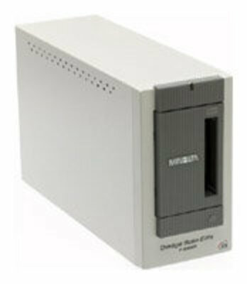 31 megapixel CMOS sensor that can detect finely detailed shapes as well as newly designed optics, the RANGE7 achieves the highest level of guaranteed accuracy for a non-contact camera type 3D measurement instrument, with an accuracy of ±40µm* according to ball bar accuracy testing based on VDI/VDE 2634 guidelines.
In addition, the RANGE7 has been designed with the concept of on-site use, minimizing the influence of instrument tilt, temperature changes, etc. at the time of measurement in order to provide high reliability in actual use environments such as in factories, etc. Further, the new sensor and original measurement algorithm provides an expanded dynamic range. Even objects with gloss, such as metallic surfaces, etc. can be measured.
2 High-speed scanning of approximately 2 seconds per shot and various other new functions provide improved operating characteristics.
Original high-speed processing circuits enable high-speed scanning of approximately 2 seconds per shot. TELE and WIDE lenses can be interchanged according to the measurement subject to provide a broad scan range.
In addition, the RANGE7 is equipped with a 3D preview function that lets users predict the measurement results and check for scan area depth, dead angles, scan problems due to surface conditions, etc. beforehand to greatly reduce scanning mistakes. Plus, the autofocus (AF) function has further advances that only Konica Minolta could provide, with a multifocus mode that automatically shifts the focus position to provide sharp, high-accuracy 3D measurement data and a point AF function that adjusts the focus to the point specified by the user, enabling scanning work to be performed without being concerned with fine positioning of the measurement subject.
3 Compact, lightweight (approx. 6.7kg) design is less than 1/2 the size and weight of previous models.
The size and weight of the RANGE7 are both less than 1/2 those of previous models, and the compact, lightweight design enables the camera and controller to be integrated in a single body weighing approximately 6.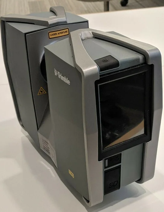 7kg to provide high mobility in measurement environments.
In addition, when the optional special stand is used, the RANGE7 can be easily moved about and measurements taken when necessary for stress-free work. (Of course, as with previous models, a tripod can also be used.) Plus, user calibration can be performed with the RANGE7 mounted on the stand.
4 Newly developed scanning software can handle large volumes of data and provides improved operating characteristics.
The newly developed 3D data-processing software RANGE VIEWER controls RANGE7 scanning and provides editing functions from measurement data alignment to merging. RANGE VIEWER employs a new GUI that provides seamless operation between scanning work and scan data editing work. In addition, RANGE VIEWER is Windows Vista 64-bit compatible, enabling the handling of large volumes of data. Plus, the navigation function displays operating methods and procedures in a navigation window, so that even first-time users can operate the RANGE7 quickly and easily.
Read more
Conferences and events Scanners
OCS Distribution
02/15/2022 | Online
Revolutionary imaging technology in new Fujitsu fi-series
Presentation PC, Scanners
OCS Distribution
12/16/2021 | Online
New scanner model of the ScanSnap 9 line0003
Webinar Printers, Scanners
OCS Distribution
02/18/2021 | Online
Reimagined by ScanSnap
Conference Scanners
Softline
10/26/2020 | Online
Digital transformation in work with documents powered by ABBYY and HP
Webinar Printing devices, Scanners, EDO
Konica Minolta
06/09/2020 | Online
Konica Minolta Digital Printing Automation
Webinar Printing devices, Scanners, IT in business, IT optimization
Konica Minolta
06/04/2020 | Online
Digitization, accounting and storage of financial documents (cancelled)
Webinar Printing devices, Scanners, IT in banking and finance, EDI, IT in business
Konica Minolta
05/21/2020 | Online
Modern printing center of an educational institution: relevance, structure, automation
Webinar Printers, Scanners, IT in Education (EdTEch)
Softline
05/20/2020 | Online
Digitization of real objects using 3D scanning for solving problems of reverse engineering and quality control
Webinar Scanners, PLM, Engineering
Konica Minolta
05/15/2020 | Online
Securing data on the Konica Minolta 9 MFP0003
Webinar Printing devices, Scanners, Information security
ELAR
10/15/2019 | Nizhny Novgorod
Presentation of the ELAR planetary scanning complex Plan Scan А1VTs-35
Presentation Scanners, Electronic Archive
Smile-Expo
04. 10.2019 | Moscow
3D Print Expo 2019
Exhibition Printing devices, Scanners, software, 3D printing
Top 3D Shop
04/19/2019 | Moscow
Top 3D Expo 2019
Conference VR, Printing devices, Scanners, Innovations, Virtualization, 3D printing, Biometrics, Nanotechnologies, Additive technologies
OCS Distribution
09/13/2018 | Nizhny Novgorod
Product Sales Conference 2018
Conference Scanners, Big Data, Wi-Fi
Smile-Expo
10/13/2017 | Moscow
3D Print Expo 2017
Exhibition Scanners, 3D printing
Aflex Distribution
07/18/2017 | Moscow
SOICA - the best solution for digitization and recognition of paper documents
Webinar Scanners, EDMS
NURBS Surfaces for Flight Simulation Software|PolyWorks
Industry
Creation of surface data for computerized flight simulation
Lockheed Martin meets the tight deadlines for 3D scanning and point cloud processing of a 1950s fighter jet.

In 2005, Lockheed Martin's Guided Missiles and Fire Control Systems division was intrigued by the aerodynamics of the Swedish-built 50-year-old Saab A-35 Draken jet fighter. The aerodynamicists at LM M&FC needed to get a very accurate data map of the aircraft that could be imported into engineering analysis tools to get real aerodynamic performance.
Complete and accurate data on the surface of the entire aircraft was required, as well as scans of weapons and gun bays with high resolution. Lockheed Martin turned to Exact Metrology to use their scanning capabilities to generate surface data and feed it into computer flight simulations.
This data was needed to ensure that weapon delivery systems would survive the combat environment of the 21st century. Aerospace contractors such as Lockheed Martin are constantly looking for ways to reduce high testing costs. One solution is to use commercial contractors instead of a military test facility and digital rather than physical means.
Task
- Capturing a 3D shape of a full size 50 ft (15.2 m) aircraft with a 31 ft (9.5 m) wingspan
- Fast Delivery of NURBS Surfaces to Modeling Software
- Data processing from high and low resolution scanners
The company had three big problems with scanning and digitizing:
- Speed: Lockheed Martin was in a hurry because the company needed 90 days to continuously process flight simulation data. The initial surface data needed to be received in a week, and Exact Metrology provided them.
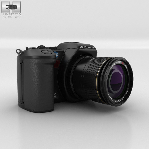
- Model size: Draken was a huge model to digitize. The aircraft is over 50 feet (15.2 m) long, with a wingspan of 31 feet (9.5 m) and a rudder height of nearly 14 feet (4.3 m). To minimize file size, two types of scanners were used: a high resolution scanner (Vivid 910 from Konica-Minolta) for high detail areas and a low resolution (and faster) scanner (Cyra2500 from Leica) for flat areas.

- Flexibility: Exact Metrology needed a software solution to process data from high and low resolution scanners.
To meet these challenges, Exact Metrology turned to PolyWorks®, InnovMetric Software's leading point cloud processing software solution.
Solution
Selecting the right crew on the field
Exact Metrology was given this job because of its unique experience in long and short distance scanning. It also helped that Exact Metrology responded immediately.
Lockheed Martin called the week before Thanksgiving (2005). Matt Kappel, manager of Exact Metrology, and the scanner operator flew to Los Angeles three days later. The scan was completed in two
days, and they were back home in time for Thanksgiving. The scan was carried out at Inyokern in the Mojave Desert in California. Six of the remaining Draken aircraft were repaired and sent there.
Exact Metrology's Draken project needed to rapidly process several gigabytes of point cloud data with widely varying resolutions - up to 10,000 times or five orders of magnitude - into a single CAD model. In the high-resolution work, Exact Metrology collected 266 point clouds, averaging 250,000 points each. The scan was performed at close range, images of about two square feet were obtained using a Minolta Vivid 9 scanner.10.
Low resolution scan was performed with the Cyra2500 from Leica Geosystems. About 20 million points were collected for these scans. “It was accurate enough for even the smallest aerodynamic shapes, but not high enough in resolution to capture unnecessary data like rivet heads and hinge points,” Kappel said. “Working at low resolution was more like a shooting app for us.”
After all the scans and digitization—about 250 high and low resolution scans, totaling 4.6 gigabytes of data—the final result, handed over to Lockheed Martin by Exact Metrology, was a relatively small uncompressed file of 200 megabytes (MB).
Scan Alignment
The PolyWorks IMAlign module was used to combine 260 scanned images into a single model. The PolyWorks mate method does not require the use of targets or markers on the part. Instead, the geometric shape of the scanned images themselves is used to align them with each other. “Not having to use targets on the plane has greatly improved the scanning process,” said Kappel.
Polygon
After the scans were combined, the resulting point cloud model was converted in the PolyWorks IMMerge module into a polygonal model in the Stereolithography Tessellation Language (STL) format. PolyWorks creates a polygon mesh (triangles) adapted to the curvature of the surface, maintaining high resolution around edges and fillets, while creating larger triangles in flat areas. Some simulation software packages can handle STL files, however the system used by Lockheed Martin M&FC does not support them. A file suitable for use in CAD was required.
Meshing curves
To create a model usable in CAD, PolyWorks calculates a mathematical representation of surfaces called NURBS (Non-Uniform Rational B-Splines) on a polygonal model. Before computing NURBS surfaces, a network of curves is built on the polygonal model to determine where the surfaces need to be fitted. PolyWorks provides both automatic and manual tools for creating a network of curves. Element curves can be extracted with a single click using PolyWorks extraction algorithms. And the network curve can be tuned manually using methods that require only a couple of mouse clicks from the user.
NURBS surfaces
The NURBS surfaces were then automatically fitted to the network of curves. These surfaces were exported as IGES or STEP files to the Lockheed Martin Analytical System. The final results met Lockheed Martin's requirements in terms of accuracy, file size, and number of fragments.
PolyWorks creates NURBS surfaces that really work in CAD.
The quality of NURBS surfaces is largely influenced by three factors:
- High quality PolyWorks polygon model underlying NURBS surfaces.
- Ability to define element critical curves when building a curve mesh and restrict NURBS surface generation to these critical curves.

- Ability to use T-junctions when creating a network of curves, which provides a more logical layout of fragments.
Benefits
From scan to final documentation, it took Exact Metrology two and a half weeks to collect, edit and format the vast amount of scanned Saab A-35 data to Lockheed Martin's specifications. “For a multi-gigabyte job, it's very fast,” Kappel said. According to calculations, savings in data collection time ranged from 67% to 80%, and in data processing time - 50%.
“Every Lockheed employee we worked with told us they were delighted with the quality and completeness of the data. There were no crashes or restarts that could break the simulation schedules. The InnovMetric Application Specialists were very helpful. It's like having an extra technician on our staff to help get through the tough times." Matt Cappel, Exact Metrology Manager
Quantifiable Benefits:
- The entire aircraft, every outer surface was scanned and digitized in two days by just two people.
 Other methods would require two to four times longer time, so the data collection time could be reduced by 67-80%.
 - Only PolyWorks can accurately process 4 gigabytes of data. Otherwise, the file would have to be divided into several parts, which would require additional steps for merging and collecting data, and would increase the processing time by two or three times.
- Competing packages were nowhere near as fast, and time was of the essence. PolyWorks saved about two weeks compared to less efficient programs.
- Significant cost savings from computer simulations instead of physical wind tunnel testing.
Future
As Lockheed Martin explained to Exact Metrology, the goal of the Saab A-35 project was to get a better understanding of the aerodynamics of a potential test aircraft from a commercial company, and it was done.
Draken's aerodynamics were revolutionary for their time and are impressive even today, half a century later.