3D printer wire gauge
How to Choose Wire Gauge and Length for Your 3d Printer
Home
Duet Wifi
How to Choose Wire Gauge and Length for Your 3d Printer
How can you calculate the wire gauge and length for 3d printer wiring? Most 3D printers use either 12V or 24V. The hotend of a 3D printer may draw up to 4A, while a heated bed draws nearly 12A. If the wire is not large enough or longer than needed, it will have more resistance which means less watts going through the wire. Copper wire size uses American Wire Gauge (AWG) which determines how much current it can handle safely. To calculate 3d printer wiring calculations, divide Current in Amps by Length in Feet to identify the correct size of wire material needed for your 3D printing project.”
Stepper Motor WiringRated Current is the maximum current that can pass through both windings at the same time. Set the motor current to no more than about 85% of the rated current. To get maximum torque out of your motors without overheating them, you should choose motors with a current rating no more than 25% higher than the recommended maximum stepper driver current.
- Nema 17 Stepper Motors: 22 AWG wire with 4 conductors
- NEMA 17 motor wires are 26 AWG
Most motor torque data assumed 24 Volts, at 1.1 amp to 1.5 amp. Roughly 26 to 36 Watts, but remember that’s “chopped” or pulsed.
Wire size is based on power transmission requirements and length of wire.
If your wire gauge is not large enough or longer than needed the resistance will be higher This means less watts going through the wire. Copper wire size uses the American Wire Gauge (AWG). The lower the gauge number, the less resistance the wire has and therefore the higher current it can handle safely.
Most motor torque data assumed 24 Volts, at 1.1 amp to 1.5 amp. Roughly 26 to 36 Watts, but remember that’s “chopped” or pulsed. Wire size is based on power transmission requirements and length of wire.
Recommended Wire Size- 10 gauge wire – 30 amps
- 12 gauge wire – 20 amps
- 14 gauge wire – 15 amps
- 16 gauge wire – 10 amps
- 18 gauge wire – 7 amps
- 20 gauge wire – 3 amps (or slightly more)
- 22 gauge wire – 2 amps
- Maximum motor current 1.
 5A peak => Stepper motor rated current <= 1.9A
 - Maximum motor current 2.5A peak => Stepper motor rated current <= 3.0A
- Maximum motor current 1.6A peak with good fan cooling => Stepper motor rated current <= 1.7A.
3d printing at a higher speed uses more current and can cause wire overheating if wire thickness is not thick enough. Use motors with lower rated current (e.g. 1.0 to 1.2A) and 24V power, then the drivers will run cooler.
Duet 3 CurrentDuet 3 Mainboard 6HC and Expansion board 3HC has a recommended maximum motor current 6.3A peak/4.45A RMS) => Stepper motor rated current <= 6A
Duet 3 Toolboard has a recommended maximum motor current 1.4A peak) => Stepper motor rated current <= 1.75A
One solution is twisted pairs of wire to have one wire carrying the current while the other brings the current back. Use a shielded 4-core high current wire, so that the wiring creates much less capacitive and induced interference or a twisted pair of twisted pairs.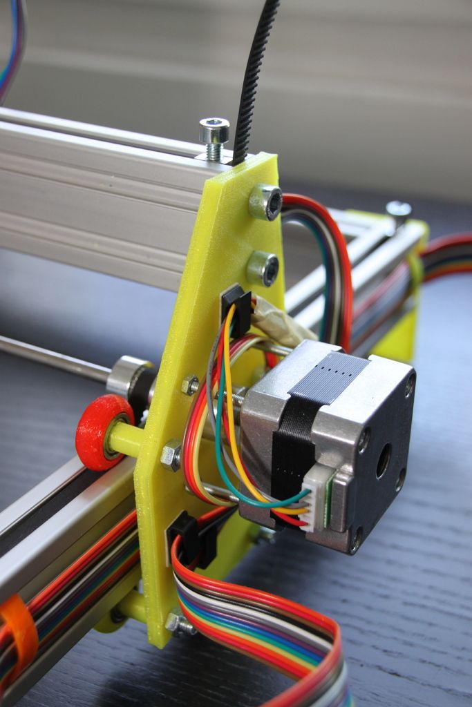
Each individual winding should have a twisted pair, and these two pairs should be twisted (in the opposite sense) together. Twisted pair will reduce induced interference to a minimum, and twist-on-twist is a very flexible way to combine 4 wires. Alas the construction will couple capacitively to nearby signal cables, so it pays to keep separate from them, or ensure all signal cables are shielded. Signal cables are things like limit switch wiring, encoders, etc….
Using a cordless drill and a bench vice, keep enough tension to prevent kinking, and reverse briefly to lose any torsion before releasing the wires.
Wire Connectors
The Molex 4 pin connector are rated at about 14 Amps (.093 inch / 2.36 mm diameter terminals.
Calculating the wire sizeA higher voltage means a lower current for the same amount of power. This gives you the opportunity to use smaller wires for the same job. Voltage is proportional to the current. A higher voltage means a lower current. Wire size influences the amount of current that can pass through it.
- A thicker wire will have less resistance per length
- Less resistance means loss
- The less loss means less temperature increase
In terms of wire size, 24V has an advantage over 12V, as the wires can be much smaller. A power supply of 300 watts running at 12V or 24V, will use less wire.
Wire Sizing Chart and FormulaCalculate the Voltage Drop Index (VDI) using the following formula:
- VDI = AMPS x FEET ÷ (% VOLT DROP x VOLTAGE)
- Determine the appropriate wire size from the chart above.
To compensate for voltage-drop, heat and current changes it is recommended to use 6 gauge wire and 4 gauge for over 15 feet.
While a Duet 3 won’t be replacing the Duet 2 anytime soon, it’s a much more professional electronics board that adds a range of options and functionality to your machine build. Although the Duet 3 may be overkill for most users, these options are not for everyone you do get much more out of Duet…
Keep reading
How To Wire The Duet 3 Mainboard 6HC The Duet 3 is a great board for your 3d printer, but wiring it up can be confusing. This tutorial will walk you through how to wire the Duet 3 mainboard 6hc to your Workhorse 3d printer. Duet Wiring Instructions This is a guide on how to…
Keep reading
Keep reading
DuetWifi Expansion Board Wiring and Firmaware Configuration
Keep reading
Stepper Motor Color Coding of Wires For any stepper motor to be wired up properly, we’ll need to determine which wires are “pairs” or connected to the ends of each coil. These are usually referred to as coil “A” and coil “B”. The exact order of the pairs Black/Green or Green/Black of pins does not…
Keep reading
What Size Stepper Motor Should You Use? While the size of a stepper motor is just the footprint it’s the winding that determines torque. There are Nema 17’s with as much torque as a Nema 23. Most 3d printers use stepper motors to drive z-axis motion lead screws to raise or lower the bed or…
Keep reading
3D Printer Kits & Parts
Shop 3D Printer Kits
Like this:
Like Loading...
electronics - Using CAT6 cables for 3D printer motor / sensors / fans
Asked
Modified 5 years, 10 months ago
Viewed 6k times
$\begingroup$
I'm considering using CAT6 cables to connect my printer's extruder assembly to the control board. They seem like an elegant solution, but I've read conflicting opinions online on whether or not this would be feasible.
I would like to know if CAT6 cables can handle the required current, whether I should be worried about electromagnetic interference or other problems, and how I should pair up the wires. Cable length would be 30cm max.
Here are the relevant parts:
- E3D heater cartridge (2 wires)
- E3D thermistor cartridge (2 wires)
- 30mm hotend fan (2 wires)
- Z-axis auto-leveling probe (3 wires)
- NEMA 17 extruder motor (4 wires)
- 50mm part cooling fan (2 wires)
[cable A] I imagine I would use one CAT6 cable for parts 1-4, which form a logical unit (and in the future I might combine them into a removable module). I've been given to understand that power for the fan can be spliced from the z-probe or heater cartridge, so 8 wires should be enough.
[cable B] I would use a second CAT6 cable for parts 5 and 6. There will be two spare wires, so I could potentially double the bandwidth for the motor.
- electronics
$\endgroup$
1
$\begingroup$
The ampacity question is not completely answerable because CAT6 does not specify wire gauge, so the current limit will depend on the specific gauge you get. CAT6 can be anywhere from 22 AWG to 24 AWG, and depending on who you ask this can be good for as much as 7A or as little as 0.5A. Given that you will have a bunch of wires in a bundle, this may cause them to heat up more than if they were in free air. For the steppers (1-2A) a single wire should suffice, but for the heater (around 3-4A) you might want to double up.
EMI will likely not cause any problems regardless of how you wire things up. CAT6 cables have the wires twisted in pairs of 2. Some people recommend to take advantage of these pairs: the +12V and GND of the heater should use a pair, each of the two coils of the steppers should have their own separate pairs. The reasoning behind this is that with equal current flowing in opposite directions in each wire of the pair, the generated electromagnetic fields will cancel out.
Twisted pairs are usually used when dealing with multiple pairs of wires that are carrying high frequency signals that might affect each other. The main concern for crosstalk in this application is if the stepper motor might cause the endstop to be erroneously triggered, but this is only a concern during homing when the feedrate (and thus frequency of the signal) is low anyways.
$\endgroup$
$\begingroup$
I did this for some of the wiring on my printer, and it's working fine so far. The two cautions are:
At @tom pointed out, the heater is the high current item, so be careful of the wire gauge, and avoid running the wire where air can't circulate well to cool it. Wire ratings differ greatly depending on whether they're in a bundle (poor air circulation) or free.
For the most part I agree that EMI shouldn't be a problem -- but if you switch to thermocouples it might become a problem -- they're much more sensitive, and this might have been part of the problem I described at How to get consistent and accurate readings from thermocouples? (though alternate wiring didn't completely solve the problem in that case).
$\endgroup$
$\begingroup$
CAT6 cable by itself is not a problem, it is typically 23 AWG solid core wire which can take you to 4A just fine. The real problem comes from the connectors you use. CAT6 usually goes hand in hand with 8p8c ethernet connectors which only have contacts rated to 500mA.
Also typically CAT6 cable is meant to be stationary (hence the solid core wires), so I'd go for something stranded. McMaster sells some nice cheap cabling that fits your needs, and it's actually meant for moving platforms like a CNC machine.
$\endgroup$
1
$\begingroup$
I've used some cat 6 in one of my printers and just to be safe I used 4 wires for the extruder heat block, 2+, 2-
On the thermistors 1 is more than enough for each +/-.
I also stripped the thick shielding off and used some 'curly' cable organizer in it's place, not the shielding on the wires but the cord. So i could fit 2 cables in slightly more than the same space as one. You are probably doing this to keep it organized too but this is an option if you run out of space in your wire runs.
$\endgroup$
How to safely extend silicon heating wires?
heated bed wiring
I'm in the middle of building a D-Bot printer and I'm running into a bit of a problem when it comes to heated bed wires. The heated layer is an aluminum plate with a silicon heater attached to it, and the heater wires are not long enough to pass through the resistance circuit when the Z-axis is fully extended.
Silicone gasket 120VAC / 750W and will be turned on/off with Fotek SSR. The heater wires are cloth covered and probably 22-24 AWG in length. (Sensor not marked)
I suspect I will need to extend the wires by inserting some kind of sleeve at the top of the resistance circuit, but I'm not sure if there are specific wire requirements for an AC powered heat table.
For this purpose, I was wondering:
- Is there a specific wire gauge that I should use for heater wires, and should it have a specific sheath?
- Which type of connector is best for safe wiring in this case?
Thank you in advance!
@Bluetopia, 👍 0
Talk
3 answers I would recommend 18 AWG or thicker.
 You don't need a specific style of insulation to do this (other than what's rated for the voltage and temperature the wire has to withstand, but the most commonly encountered wire should be good).
 A good way to connect the wires would be to solder them. If you don't want to solder, there are many wire-connecting products on the market. The butt connector you crimp might be a good option, or you could use a WAGO clamp. Regardless of which option you end up using, be sure to provide adequate voltage relief, as the connection point (whether soldered or with a connector) is more likely to fail from fatigue.
, @ Tom van der Zanden
▲ 0
750W at 120V is about 6.3A. the temperature rises.
I did it for you. With 10 feet (2x5 feet) of 20AWG wire and 6A current, 7W is dissipated on the wires.
This is 0.7 W/ft which is normal for silicone wires and also because the table is not working at 100% except for the initial heating (and then the heat goes into the air around which is normal anyway).
If you use another site, you can see that 20 AWG with 6 amps produces about 10 degrees of temperature rise in free air. Silicone insulation will make this worse, but silicone holds up well above 100°C...
Use thicker wires if you can, or continue if you can't.
The most important thing is to connect them very effectively so that no additional resistance occurs. I would place them next to each other and physically solder them. Then heat shrink tubing around the joint.
See Information on what should not be used to connect
, @ FarO
▲ 0
To add to the answers here, use finely wound table wire. It works best with constant bending. Fine-grained wire is hard to come by, except it's usually used for wall warts/ac adapters. They come in the heavier gauge you want, just check the label on the wire.
, @ ChinchillaWafers
Which speaker cable should I buy and which one should I never buy? - Article from the 1-TECH Blog
- Reviews (65)
-
Rate this article:
Very often, when choosing an audio cable for a speaker system, people think that the more beautiful the cable, the better it works. And a beautiful "wrapper" is more often specially used just for the visual appeal of the product. Also, as a rule, a cable buyer rarely finds time to listen to the proposed model, or even simply there is no such opportunity at the outlet itself.
Everyone understands that a professional cable is a good cable, but not everyone knows that professionals do not need "show-offs" in the form of juicy insulation, colorful packaging. Therefore, a professional speaker cable will have the simplest appearance, and its insulation will be plain or just black.
But the consumer buys with his eyes... Therefore, we decided to prepare this short article to help beginner music lovers and home theater lovers.
A bit of theory..
No matter how good amplifiers and speakers are, without wires connecting them to amplifiers, they will be gloomy silent. In order for the sound from the speakers to please the ears, you must first please them yourself and connect the wires that you need to them. Usually, the cables that are used to connect to speakers are called “acoustic” or “speaker”, and now also “speaker”.
Let's start simple:
The ability of wires to pass electric current through them depends on the materials used in their manufacture. And, surprisingly, silver, not gold, is the champion among conductors. The first 4 places of the competition in conductivity among chemical elements are distributed as follows:
| 1 | Ag Silver |
| 2 | Cu Copper |
| 3 | Au Gold |
| 4 | Al Aluminum |
To avoid a short circuit, it is customary to insulate the wires, so the metal conductors are wrapped or filled with something that does not conduct electricity. There are no types of insulation, but its main task is to prevent the wires from closing with neighbors or with a person.
The wires themselves consist either of a single thick wire or of many thin wires (“strands”) twisted together. And they are called “single-core” or “multi-core”. A stranded wire loses to a single-core wire in the ability to conduct current, but wins in many other competitions, especially in flexibility and “non-breakability” from repeated bending. But we do not advise you to be very mistaken - everything breaks from repeated kinks and the stranded cord too.
How does the cable affect the sound quality?
First about the “elite” Hi-Fi and Hi-End standards: Discussions on the topic “High fidelity” for at least 50 years .. And then and now the assessment was not made by devices, but by experts. And then and now the conclusion is the same: if you want to hear the correct reproduction - go to an acoustic concert. There is not and will not be an absolutely linear technique in the world that will record and reproduce sound without distortion as it sounded during recording. Distortions are inevitable, and speculation on this will have no end. And what technique to choose remains a matter of taste and is limited by the size of the wallet and common sense, if any. The most important criterion is whether you like it or not.
For example, the statement that the use of silver-plated copper in Hi-End cables improves the reproduction of overtones is, as one of our good friends said, “anti-tank nonsense”. Not only does silver not differ much in conductivity from copper, but also the effect of the propagation of high-frequency currents along the surface of the conductor begins to affect the radio frequency range, and for the sound and ultrasonic ranges it is negligible. But the wires are “richly” decorated and people with wallets willingly believe that only this cable is needed by their equipment.
So about such a cable, one can safely quote V. Vysotsky: “it was of good use as from a goat's milk, but there was no harm either.”
What about oxygen-free copper OFC (Oxygen-Free Copper) and monocrystalline copper OSS (Ohno Continuous Casting)? Both varieties have a lot of wonderful properties. Oxygen-free copper is purified from oxygen and oxides dissolved in it by heating and pouring in a vacuum or other environment that provides protection from oxides and other impurities. Its structure becomes homogeneous and does not create obstacles for the movement of charged particles. For the production of OSS, an even more sophisticated technology is used. Both types are widely used in microelectronics, space and other high-tech industries.
But in relation to acoustics, one should remember the popular expression of physicians “Vitamins enrich the patient's urine and the pharmacist's pocket”. All the reasons a la “reduces the degree of sound distortion and the level of extraneous noise”, “are not subject to internal corrosion and their conductivity does not deteriorate over time” are intended for the inexperienced ear of the willing to pay buyer.
Once again: if the conductor is made of copper, then whether it is “single-crystal” or “oxygen-free”, or both together, does not have any significant meaning for acoustic systems. All these advantages appear below the sensitivity zone of the human ear and the conductor noise is several orders of magnitude lower than the noise level emitted by transistors and other radio components.
For speaker cables, the main thing is that they have copper in them and that it does not rust in the manner of “Chinese” brass on plumbing fittings. As for “non-corrosion resistance”, copper feels great even in river and sea water, so inside a normally made insulation it will last a hundred years.
What is worth knowing about the cross section of the speaker cable?
Losses of transmitted energy, depending on the cross section of the conductor. To find out what section the wire has, it must be cut exactly across and calculate the area of the end.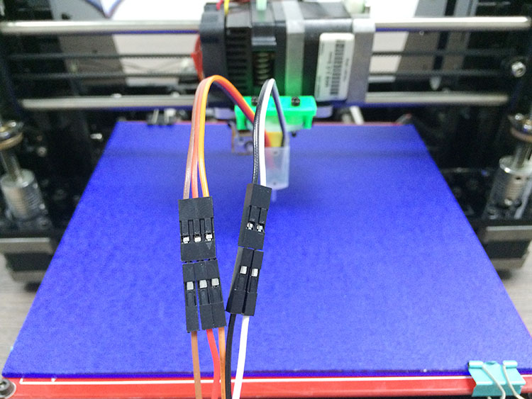 Accordingly, the thicker the wire, the larger the cross section.
In the US, they invented their own standard, calling it “ American Wire Gauge System ” or abbreviated AWG , which, in order to more sting the Europeans. they also turned it upside down, that is, the larger the caliber, the smaller the diameter. The table of correspondence of calibers to areas is extensive, but for example, here are a few commonly used sizes for single-core conductors:
AWG value
Diameter, mm
Cross-section, mm2
27
0.361
0.1023
25
0.405
0.128
26
0. 455
455
0.162
24
0.511
0.205
22
0.644
0.325
20
0.812
0.517
19
0.912
0.652
18
1.024
0.8235
17
1.15
1.038
16
1.29
1.307
15
1.45
1. 65
65
14
1.628
2.081
13
1.828
2.624
11
2.308
4.17
Why do you even need to calculate the cross section of the speaker cable for laying speaker cords? The fact is that if the metal is not an ideal conductor, then it heats up from the current passing through it. This means that if you have powerful acoustics, you will have to take a fairly thick wire. And there is also a direct dependence of the cross section on the length. You should know that the longer the path to the speaker, the greater the resistance of the conductors, and hence the loss in volume and quality. But the larger the cross section of the conductor, the lower its resistivity, therefore, by taking a thicker wire, you are guaranteed not to lose a single precious watt from the amplifier released.
An example of calculating the required section of an audio cable:
Home acoustics are most often connected with a two-wire multi-core cable and this type is the most common speaker cable option.
It remains to determine its cross section. To do this, you need to find out how much the columns themselves resist the current supplied to them. To find out what resistance your acoustics have, you need to look in the passport or on the back wall. If you didn’t find out anything, look for a device that measures resistance (tester, multimeter, ohmmeter) and measure it yourself.
The lower the column resistance, the more current it will consume, which means that a larger cross section will be required. There is such a parameter as current density, that is, what current flows through a unit area. It remains to calculate what current your acoustic system will consume, for which you need to use this formula: I = PR, (where I is current, P is acoustic power, R is resistance). Dividing the obtained value by the standard current density, we obtain the minimum cross section. For example, a column with a power of 100 watts and a resistance of 4 ohms needs a current equal to the root of (100/5) = 5 amperes. If you read the PUE (look for yourself what it means), then the nominal current density for copper wires lies in the range - 2.7 ... 3.5 A / mm2. That is, the minimum wire cross-section for such speakers is 1.8 ... 2.3 mm2. That's why you should dance. For complete confidence in our calculations, it remains to determine what resistance this wire will have. To do this, we find the specific resistance of copper conductors - 0.017 Ohm•mm2/m. We divide this value by the cross section, multiply by twice the length of the cable and we get that the maximum resistance for 10 m of wire with a cross section of 1.8 squares will be 0.017 / 1.8 * 20 = 0.189Ohm. This is 21 times less than the resistance of the speaker, which is quite consistent with anything seriously unjustified requirements for Hi-Fi technology.
 Calculations have shown that for lengths within 5 meters, the cable resistance can be safely neglected. The main thing is to be sure that the wires are really made of copper, and not a copper-plated rag. When the sellers will assure you that you need at least 4 squares, this means that they trivially want to cash in on you.
Which speaker cable should I choose?
Like almost everywhere else, the main selection criteria are quality and durability.
It's sad, but if you need both, then you won't be able to save much. In addition, imitation technologies are now extremely developed and we regularly buy at “favorable discounts”, and almost immediately we understand that we have not received the benefit.
Professional speaker cables German brand KLOTZ a-i-s
| LYP0.. | LY2.. | SCY2.. | SCh3. . . |
| Parallel conductors. Single insulation (black, white, transparent) | Conductors are intertwined with each other with a certain pitch. Double insulated. | Conductors are intertwined with each other with a certain pitch. Double embed insulation. | Conductors are intertwined with each other with a certain pitch. Double non-combustible insulation. |
Multicore models of professional speaker cables for Bi-wiring and Bi-amping
| LSC.. | LYS.. | SCh5..D | SCFR4.. |
| Conductors are intertwined with each other with a certain pitch. Double insulated. | 2.5 mm² sensor wire added. Double reinforced insulation. | Conductors are intertwined with each other with a certain pitch. Double non-combustible insulation. | Twisted conductor structure. Non-combustible insulation of increased reliability. |
What is important to pay attention to when buying a speaker cable?
How a copper conductor looks. If the cable is very soft or very hard, then this is a reason for doubt. It may well be that you are offered a copper-plated alloy. not pure copper. All alloys are obviously worse than copper in conductivity. The argument that they are better than copper because they do not oxidize or rust is an attempt to mislead. Copper oxidation processes are very slow and if the contact was normal, then nothing will happen to it for many years. And the rest of the copper is covered with chemically neutral insulation and it will additionally prevent the destruction of the metal. By the way, this is a very important indicator of quality: the “freshly bare” strands of a new wire should not be darker than untreated copper, if this is not the case, then either the copper is of terrible quality, or the insulation is aggressive and will soon corrode the metal. We came across similar samples that literally crumbled in our hands.
- Feel and remember the insulation. Normal should not stick to hands and leave traces of paint. It should be moderately soft, elastic, but strong and not crack at a sharp bend. Double insulation is more expensive than single insulation, if this is not the case, then you need to clarify why.
- Naturally, there should be a color marking of one of the wires. Otherwise, you will suffer from “phasing” your acoustics, and this is extremely important for surround sound systems, so that the speakers oscillate in the same direction.
- Manufacturers of high-quality cable must label their products and put meter marks so that it is easy to count the right pieces.
- To be sure that this is not a fake, it makes sense to search the manufacturer's network and see how its products look and whether they are similar to what they offer you.
Responsible sellers value their reputation and try not to deceive anyone, except perhaps tax collectors and customs officers. The point is small - to find a responsible seller. By visiting our website, you have come to the right place and we, appreciating your trust, will try to make your acoustics sound good. We offer the best speaker cables at affordable prices and ready-made solutions for connecting Hi-Fi and High-End audio systems.
Answers to Frequently Asked Questions for Speaker Cable Customers
Here is a list of answers to questions that a buyer should ask himself when choosing a speaker cable:
Solution evaluation
Question
Excellent
Satisfactory
Rather bad
Where to buy?
From trade sellers
Electronics stores
Household stores, markets
How many strands should be in the wire?
Many and specially entwined
Minimum 7
One
What metal should the cable be made of?
Copper OFC or RF
Electrical copper
Special "copper" from China for developing countries, aluminum
Is a silver-plated cable required?
For your taste, you will not feel the difference.
No
“What is this..?”
Which section should I choose?
It is desirable to calculate
Not less than 0.5 mm2 + 0.5 mm2 for every 50 W of power
The cheaper the better, because we are not connecting an iron!
How many layers of insulation do you need?
Two
One
And why is it, let it go in parallel or fence off with matches.
What color should the wire insulation be?
Mandatory different, e.g. red and blue, outer sheath can be one color
The insulation must have a colored stripe (white, red) so as not to confuse plus and minus
What's the difference, we'll figure it out if anything .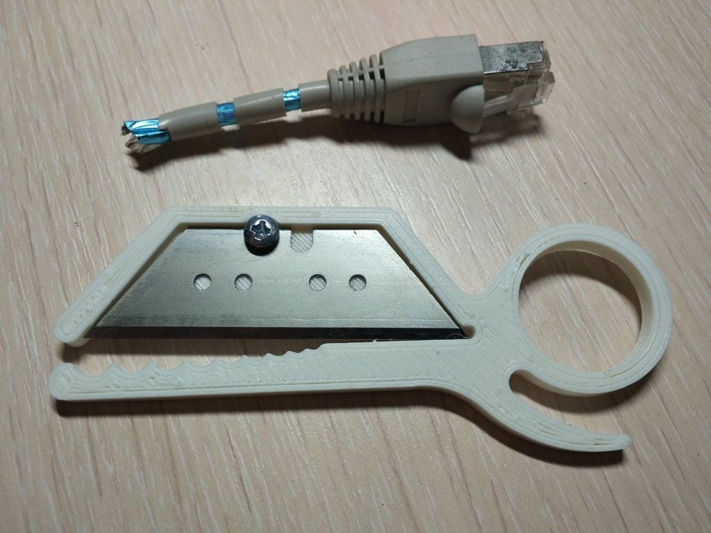 .
.
What to do with excess cable?
Cut off all excess, leaving small allowances for installation and dismantling.
First, leave a couple of meters of stock in case of some rearrangement, then cut off the excess.
Don't cut anything, shove the bay behind the column.
How to remove insulation
Special tool
Construction knife, but very carefully.
Teeth or scissors..
What should I do if, during stripping, I cut several wires and their remains slightly protrude beyond the insulation?
Clean up again
It is better to redo, but if not too many strands are cut, then you can cut them “at the root” so that nothing protrudes beyond the edges of the insulation.