Level bed 3d printer
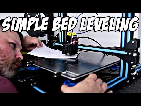
How to Manually Level a 3D Printer Bed
When you purchase through links on our site, we may earn an affiliate commission. Here’s how it works.
(Image credit: Tom's Hardware)Whether you’re using a brand new 3D printer for the first time or noticing that your prints come out uneven or, even worse, fail to stick, you need to level the print bed. Entry-level 3D printers, even those which sit among the best 3D Printers, often do away with luxuries like color screens, direct drives and probes for automatic bed leveling. Don’t worry, learning how to level a 3D printer bed is not hard; it just takes a little practice.
“Leveling the bed” is a bit of a misnomer. We’re actually “tramming” the print surface: making sure the nozzle is at the same height across the bed at every point on the X and Y axis.
Level is a simple, if not precise, word everyone can understand.
The biggest problem when manually leveling a 3D printer bed is finding the correct distance between the nozzle and the print surface. Too far and your prints won’t stick. Too close and you’ll damage the print surface.
Luckily for those of us stuck with manual 3D printer bed leveling, we don’t need to be laser accurate. We’re dealing with fractions of a millimeter, so pretty darn close will get us the quality we seek.
When Do You Need To Level a 3D Printer Bed?
- After assembly and before your first print.
- After changing the nozzle to make sure the nozzle remains the correct distance from the bed.
- Once a week. Even the best printer can fall out of calibration with use, so check your level occasionally.
- After a failed print. Prints not sticking? You might be out of level.
What You’ll Need to Level Your 3D Printer Bed
- A Piece of Paper: This is used to gauge the distance between your nozzle and the print bed. Computer paper is a good choice, but a piece of junk mail or a Post-It Note will work too.
- Filament: Load your printer with PLA for running a test print. PLA is a commonly used filament and sticks well without fuss. We’re using Inland PLA + Orange for this article.
- Isopropyl Alcohol : Clean the print surface before leveling. Filament never sticks well to a dirty bed.
- Paper Towel: For cleaning the bed.
- Slicer App: You’ll need to slice your test print – any slicer will do. We like to use Ultimaker Cura.
- Bed Level Test Print: There are several files online, we’ll use this one from Thingiverse. It’s sized for an Ender 3. You can size this one to fit your printer’s bed or search for a test that’s made for your specific machine.
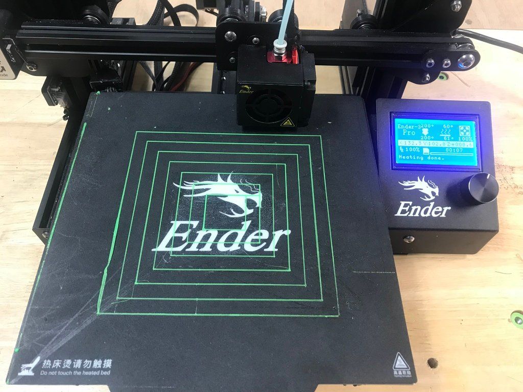
- Your 3D Printer: In this article, we’re using a Creality Ender 3 Pro FDM 3D printer. The four-point print bed is similar to many popular 3D printers on the market today, including the Elegoo Neptune 2.
Prepare your Printer
1. Clean the bed. Lightly scrub the print surface with Isopropyl Alcohol and a paper towel to remove fingerprints and any bits of leftover filament.
2. Preheat your printer and bed to its normal operating temperature. For PLA, we warm up the printer to 200° on the nozzle and 60° on the bed. Wait at least 5 to 10 minutes to let the printer absorb the heat.
Some experts believe it's unnecessary to preheat the bed, as the possibility of heat expansion is very small. We prefer to level the bed under the same conditions we use while printing.
3. Home the printer. This will take it to the 0,0,0 position.
4. Check your printer controls for an option called Bed Leveling, Level Corners or Bed Tramming. This option will move the printer around the four corners of the bed while you adjust the springs underneath.
A few Ender 3 models come with leveling aids installed. You’ll need to select “Disable Steppers,” which turns off the stepper motors and allows you to push the print head by hand.
Note: Our Ender 3 Pro has been upgraded to Marlin 2 firmware, which added a Bed Tramming routine.
5. Slide the print head (or let the printer do it) to the first corner, centered more or less over the adjustment knob under the bed. Slip a piece of paper under the nozzle.
6. Use the adjustment knob underneath the bed to raise or lower the nozzle until it barely touches the paper.
Do this for all four corners and the center. Then do it again. Leveling the bed is a balancing act where adjusting one corner can throw off the opposite corner.
(Image credit: Tom's Hardware)Run a Test Print
1. Load a bed level test print into your slicer of choice. Since we’re using a Creality Ender 3 Pro, we’ll use one found on Thingiverse called “Ender 3 Bed Level”.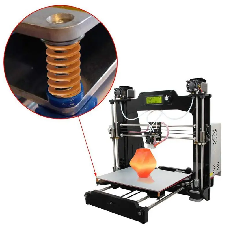 If your printer has a larger or smaller print surface, adjust the x and y coordinates accordingly.
2. Reduce the Z height to 0.4 for a single layer test print.
3. Clean the bed with Isopropyl Alcohol and a paper towel.
4. Run the print.
Diagnose the Results
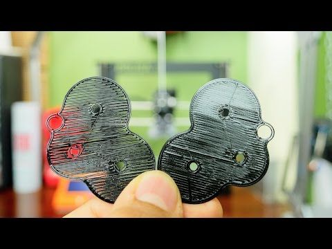
- Nozzle is too close. If your nozzle is too close to the bed, it will plow through the filament, causing a rough, uneven surface. You could have thin patches where the plastic is being pushed into the bed surface. It may be difficult to remove.
- Nozzle is too far. If your nozzle is too far from the bed, there will be gaps between the lines of filament. The lines of plastic appear rounded and may not stick to the bed at all.
- Nozzle is just right. When the nozzle is a perfect distance from the bed, it will appear slightly squished or lightly flattened.
 Lines will blend into each other with a uniform appearance. There will be very little roughness.
If the squares of the test print appear too far or close to the nozzle, make adjustments as needed and re-run the test print.
3D Printer Bed Leveling Aids
It can be difficult to achieve a perfect first layer with manual 3D printer bed leveling. Here’s a few things to try before you give up and buy a BL Touch Auto Sensor , which can be used to do auto leveling on an Ender 3-style 3D printer.
- Clean the Bed. A squeaky clean bed is extremely important for bed adhesion. Even a few fingers prints can add enough grease to make a print not stick.
- Use a Raft. Your slicer can place a chunky first layer down that helps tall or delicate prints stick. The downside is that you’ll have a rough surface on the bottom of your print. You will find rafts under Build Plate Adhesion in Cura and under Support Material in PrusaSlicer.
 Other slicers have their raft options in other menus.
 - Use Glue Stick. A washable disappearing glue stick – the purple kind – from the children’s craft aisle is a perfect adhesion helper. It lays down a tacky layer that helps filament grip the surface. Lightly smear the glue across the whole bed, then wash off after 3 or 4 prints and reapply. The brand doesn’t matter, so feel free to stock up during the next Back to School sale.
- Shim the Bed. Warped beds are sadly common in inexpensive printers. If your bed seems lower or higher in the middle – and you have a removable print surface – you can shim the bed with aluminum foil, masking tape or even a Post-It Note.
To Shim the Bed
1. Remove the print surface.
2. Place a steel ruler or similar straight edge on the bed and shine a flashlight behind it.
(Image credit: Tom's Hardware)3. Note how big the gap is and cut a piece of foil or tape approximately that size.
4. Place it on the printer bed and look for gaps with the ruler.
5. Layer additional pieces of foil or tape until the bed is mostly flat.
6. Replace the bed surface and level the bed.
(Image credit: Tom's Hardware)Get instant access to breaking news, in-depth reviews and helpful tips.
Contact me with news and offers from other Future brandsReceive email from us on behalf of our trusted partners or sponsorsDenise Bertacchi is a Contributing Writer for Tom’s Hardware US, covering 3D printing.
Topics
3D Printing
3D Printing Essentials: How to Perfectly Level your Bed
For some, levelling a 3D printer's bed can be challenging, but it doesn't need to be. Read this essential guide to see what it takes to do it right.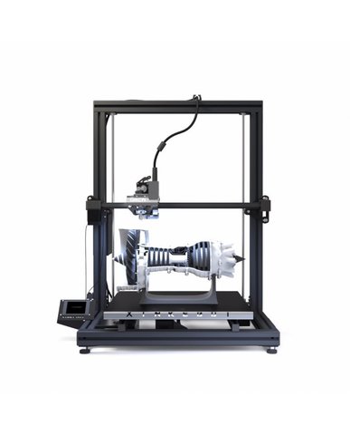
Posted on December 30, 2020
by
Alec Richter
Part of the 3D printing experience is having an acute understanding of how the machine works and how to properly calibrate it to give you the best chance for success. Making sure that the first layer of every 3D print is the ideal distance from the bed isn’t the only factor in your 3D print’s success–you also need to ensure your 3D printer’s bed is universally level. Your first layer may look perfect in the front of the bed, but it’s also important to consider how well it’s sticking in the back of the bed as well. Leveling the bed of your 3D printer is an important step in getting high quality 3D printed parts, but it can be a little tricky. Luckily, the Pros at MatterHackers are here to help. Let’s take a look at the essential lessons of leveling your 3D printers bed.
What Does It Mean to “Level a 3D Printer’s Bed”?
First, there is the important distinction that what is colloquially referred to as “leveling your bed” would more accurately be called “tramming your bed.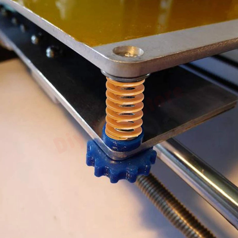 ” The goal is not to have the bed level in relation to the floor (as you might imagine doing with a bubble level), but rather to have the bed be the same distance from the nozzle across the entire surface of the build plate OR put differently the bed parallel to the printhead gantry. This in fact might mean that if you take a bubble level to your 3D printer’s bed, you will probably find that it’s skewed. However, start a 3D print that runs across the entire bed and you’ll see the first layer is perfectly flat.
Simply put - leveling your printer’s bed is exactly as it sounds. You want to make sure your bed is level so there is a precise distance between the nozzle and the entire surface of the build plate. Now, you can’t just put a standard bubble level on your bed and call it a day, because again, the “level” we are looking for is between the nozzle and the print surface - not the nozzle and the workbench, desk, or floor that your printer is sitting on.
Manual Bed Leveling
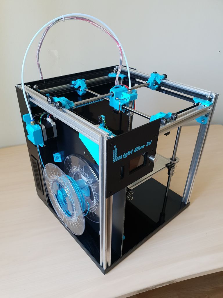
In terms of construction, manually leveling, or adjusting your printer’s bed by hand, is the simplest form of bed leveling you will find on a 3D printer. Generally, the more affordable the 3D printer is, the more likely it will be a manually adjusted bed because it doesn’t require any complex calculations or extra hardware to make it work. A manually leveled bed will have the build plate itself floating above the bed carriage–it is not rigidly mounted to the bed carriage. Instead, the build plate is secured to the carriage using a combination of screws, springs, and thumbscrews. This combination makes it so the bed can pivot and be adjusted while still being rigid enough to not bounce around while you are 3D printing.
Manually leveling the bed is a tried and true method, as long as the bed itself is flat and doesn't have any unintentional contour.
How to Manually Level the Bed
Three points define a plane, but many printers still use four screws to level the bed, with one at each corner.
- Tighten down all the screws at each corner, so you have enough room to loosen them later. Aim for screwed down halfway instead of all the way or all the way off–this will give you more room to work with.
- Home the Z axis.
- On some printers, Z0 (home) may be too far from the bed, even when all the screws are loose. In that case, you’ll need to move the Z-minimum endstop slightly lower to calibrate.
- Using the LCD menu or other interface, jog the printhead over each screw that levels the bed, insert a piece of paper between the nozzle and the bed, and loosen the screw until there’s a very slight resistance when you pull on the paper.
- You don’t want the piece of paper to be locked between the two, just enough pressure to feel the drag when you move the paper.
- Repeat this for the other screws.
- You want to make sure each screw pinches the piece of paper with the same amount of pressure to have a level bed.
- After adjusting all screws, check your work by moving the nozzle over the screws again and making sure they didn’t shift from previous adjustments.
- Start a print.
- You can make adjustments while the 3D printer is printing to fine tune your first layer.
Once your printer is leveled, it should stay that way for a while. However, it’s a good idea and maintenance practice to adjust or relevel your printer’s bed occasionally to ensure great prints every time.
Software Leveling
Ideally, manually adjusting the bed is enough to have a consistent first layer. However, depending on the quality of components used on a 3D printer, a bed may not be a uniformly flat surface to start with. In some cases, thinner 3D printer beds have a tendency to bow and warp as they heat up and cool down which means no matter how hard you try there will always be some point on the bed that will be lower or higher than the rest. Effectively, no amount of thumbscrew adjustment will compensate for a 3D printer with a bed shaped like a bowl unless you have some compensation routine, like software leveling.
What is Software Leveling?
Within MatterControl, our slicing software, there exists a guided wizard that will allow even the most extremely out of shape printer beds to have a uniform first layer. By manually mapping the bed of your 3D printer, MatterControl is able to adjust the Z values in the sliced Gcode so the nozzle is constantly moving up and down to achieve a consistent distance from the bed throughout the 3D print.
Using MatterControl to "software level" the bed will enable even the most dished and skewed bed to have 3D prints perfectly follow its contour.
How to Software Level.
You will need to connect your 3D printer directly to MatterControl by connecting the USB from the printer to your PC. Once the leveling is complete you can continue to 3D print from MatterControl or export the sliced Gcode onto an external device like an SD card or thumb drive.
- Connect your 3D printer to MatterControl.
- Under the “Controls” tab and “Calibration” subsection click “Printer Calibration”
- Follow the wizard
- Your printer will then home on X, Y, and Z and then move over the first point that needs to be calibrated.
- Insert a small piece of paper between the nozzle and the bed and slowly decrease the distance between until you feel a very slight resistance on the printer.
- Not enough to hold the paper tight, but enough to feel that it can’t easily slide around anymore.
- Repeat this process for every point of the grid until a mesh can be constructed.
- The most important thing is to have the resistance of the paper the same at every point so that it is uniform. A little too tight is fine as long as you use this measurement throughout the bed.
- Slice up a test print to check your work.
- A large rectangle that covers the bed will make it clear if any point is too close or too far at that particular point.
- Adjust the Z-Offset by baby-stepping further or closer to the bed.
After it’s all said and done, your bed itself won’t be level but your first layers will have a consistent distance from the bed which means your 3D print’s foundation will be adhered to the bed and lead you on the path to success.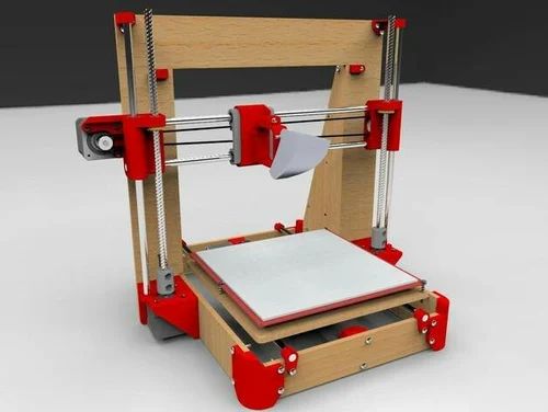 Be sure to run through this wizard again if you find that you are experiencing high or low spots in your first layer or adjust the number of points you have in your mesh grid if the trouble spots are between probe points.
Firmware Leveling
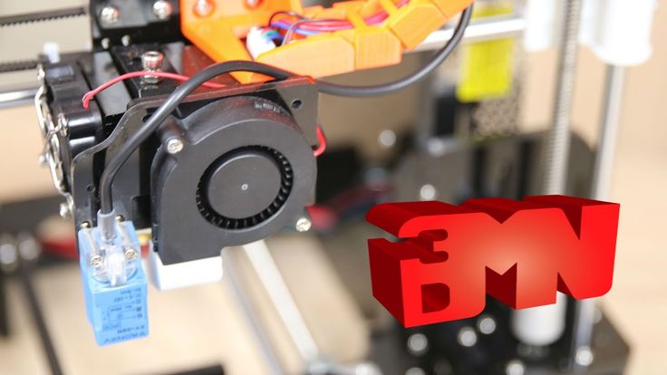
On some 3D printers, user intervention is kept to a minimum by a handful of features built into the firmware of the 3D printer, hard-coded into it to make finding the perfect first layer as hands-off as possible. By using a small probe to detect the bed and its relative distance from the Z minimum or Z maximum, the firmware is able to automatically run through a bed leveling procedure and construct a grid that will compensate for an uneven bed. Think of firmware leveling as essentially the same thing as software leveling, except the printer is doing all the thinking instead of you and a piece of paper.
After using a bed probe (seen glowing red) you can 3D print across the entire bed of a 3D printer without worrying about high or low spots.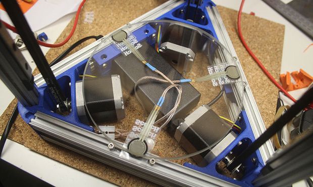
How to Firmware Level the Bed:
If your 3D printer has firmware leveling, it is likely enabled by default, rather than something you turn on if you want it. The best practice is to follow the instructions prescribed by the manual included with your 3D printer. Most 3D printers with firmware leveling will have a wizard (a guided walkthrough) incorporated into it to make set up easier. In general, the process will be similar across the different 3D printer and probe types:
- The nozzle and bed will heat up in order to allow them to expand and get a more accurate reading.
- The print head will move around the 3D printer probing various points to create a mesh of the detected surface.
- Either a series of lines will be printed to determine which Z-Offset works best, or a small test print will need to be started manually.
- The Z-offset will be adjusted through the LCD menu to move the nozzle closer or further from the bed to achieve a proper first layer and determine the distance between the probe tip and the tip of the nozzle.
Firmware leveling is a straightforward process that aims to simplify what used to be a significant hurdle for newcomers to 3D printing. By integrating automatic systems, it becomes easier to have repeatable results. Spend less time worrying about your 3D prints you just started and more time focused on slicing up your next one. There are many different probes that can be found on 3D printers, and you can check out our article on the different types to see what kinds of limitations, if any, your probe might have.
Whether you have a 3D printer that needs to be manually leveled or a 3D printer with fully capable firmware leveling, it’s important to understand the basics of how the process works to troubleshoot and calibrate your 3D printer as you become more acquainted with it. Hopefully, with the help of this guide, you now understand how to level your bed and get smooth and consistent bottom layers on your 3D prints. With this knowledge, you are well on your way to understanding the 3D printing essentials.
Happy printing!
Article Tags
- 3D Printing
- Firmware
- 3D Design
- MatterControl
- Press Releases
- Small Business
- Automotive
- E3D
- Jewelry Making
- Engineering
- Entertainment Industry
- MatterControl Touch
- ESD Materials
- NylonX
- BCN3D
- Open Source
- Crafty Pen
- Digital Fabrication Anatomy
- How To
- Hardware and Upgrades
- Tips and Tricks
- Weekend Builds
- Top Ten
- Education
- Tech Breakdown
- Women in 3D Printing
- Project Ideas
- Advanced Materials
- Reference
- Vacuum Forming
- Pulse Dual Extrusion
- Product Spotlight
- Aerospace
- Jobs
- Military & Government
- Multi-Tool Machines
- Getting Started
- Healthcare
- How To Succeed With Any 3D Printing Material
- Creality3D
- Architecture
- 3D Printer Reviews
- Hacker of the Month
Related Products
View all related productsHelp for beginners in 3D Printing.
 Part 1
 As a representative of the fab lab of my city, I am a very interesting person and I like to look for various information about 3D technologies and robotics. I want to present a small methodological guide for beginner 3D printers :).
Consider the most common reason for not sticking to the table.
problem description:
It's very important that the first layer of your print is tightly coupled to the printer platform assembly so that the rest of your side can be built on that foundation. If the first layer is not adhering to the design of the platform, it will create problems later on. There are many different ways to deal with these problems in the first layers, we'll go over a few typical causes below and explain how to solve each one.
1)Cause: The operating panel is not on the same level.
Solution: Many printers include an adjustable panel with a few screws or knobs that control the position of the bed. If your printer has an adjustable pad and you're having trouble getting your first layer to stick to the pad, the first thing you'll want to do is make sure the pad for your printer is flat and level. If the panel is not level, one side of your panel may be too close to the nozzle while the other side is too far away. Some software (for example: Simplify3D) already includes a useful leveling bed wizard that guides you through the layer leveling process. You can find this wizard by going to Tools > Bed Leveling Wizard and follow the instructions on the screen.
2) Cause: Nozzle starts too far from panel
Solution: After your panel has been leveled, you still need to make sure the nozzle is starting at the correct height in relation to the platform structure. Your goal is to find your ideal extruder distance from your plate design - not too far and not too close. For good adhesion to the build plate, you want your filament to be held slightly against the build plate. While you can tweak these settings by changing the hardware, it's usually much easier (and much more accurate!) to make these changes from within Simplify3D.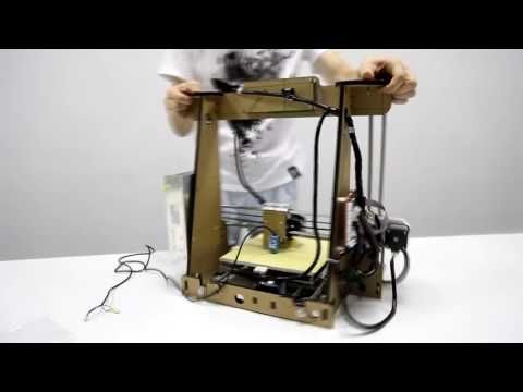 To do this, click on the 'Change Process Settings' button to open the Process Settings and then go to the G-code tab. You can use the Z-Axis Global G-code Offset to make very fine adjustments to your nozzle position. For example, if you enter -0.05mm for the z-axis z-offset code, the nozzle will start printing 0.05 closer to the platform design. Be careful to only make small changes to this setting. Each layer of your hand is usually only about 0.2mm thick, so a little adjustment goes a long way!
3) Cause: The first layer is printed too fast.
Solution: As you extrude the first layer of plastic onto the top of the platform structure, you want to make sure the plastic can properly bond to the surface before starting the next layer. If you print the first layer too quickly, the plastic may not have time to get close to the build platform. For this reason, it is usually very helpful to print the first layer at a slower speed so that the plastic has time to get closer to the bed.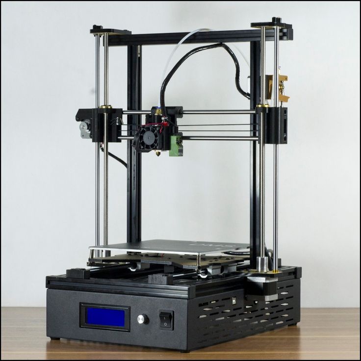 Simplify3D provides customization for the exact function. If you click on the 'Edit Settings' process and go to the Layer tab, you will see a setting labeled 'First Layer Speed'. For example, if you set the first layer speed to 50%, that means your first layer will print 50% slower than the rest of your side. If you feel that your printer is moving too fast on the first layer, try lowering this value.
4) Cause: Too much cooling.
Solution: Plastic tends to shrink as it cools from warm temperatures to cold temperatures. To provide a useful example, imagine a 100mm wide section that is currently being printed with ABS plastic. If the extruder prints this plastic at 230 degrees Celsius, but it has been applied on a cold build platform, it is likely that the plastic will cool quickly after exiting the hot nozzle. Some printers also have cooling fans that speed up this cooling process when they are in use. If this ABS part is cooled to room temperature of 30°C, a 100mm wide part will shrink by almost 1.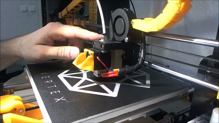 5! Unfortunately, the build platform on the printer won't shrink that much, since it's usually kept at a fairly constant temperature. Because of this fact, the plastic will tend to separate from the platform structure as it cools. This is an important fact to keep in mind as you print your first layer. If you notice that the layer seems to stick initially, but later separates from the print bed as it cools, it's possible that your temperature and cooling settings are to blame.
Many printers designed to print high temperature materials such as ABS include a heated bed to help combat these problems. If the bed is heated to maintain a temperature of 110°C for the duration of the print, it will keep the first layer warm so that it does not shrink. So if your printer has a heated bed, you might want to try a heating bed to prevent the first layer from cooling down. As a general starting point, PLA tends to adhere well to a bed that is heated to 60-70C, while ABS generally works best when the bed is heated to 100-120C. You can adjust these settings in Simplify3D by clicking on the 'Change Process Settings' button and then selecting the temperature tab. Select the heated build platform from the list on the left side, and then edit the temperature value for the first layer. You can simply double click on the value to change it.
If your printer has a cooling fan, you can also try turning off that cooling fan during the first few layers of the printer so that the initial layers don't cool down too quickly. You can do this by clicking 'Change process settings' and go to the cooling tab. You can adjust the fan speed settings on the left side. For example, you may want the first layer to start with the fan off, and then turn the fan on at full power once you reach the 5th layer. In this case, you will need to add two settings to this list: layer 1 at 0% fan speed, and layer 5 at 100% fan speed. If you are using ABS plastic, it is common to disable the fan for all printing, so entering one setting will be enough (Layer 1 at 0% fan speed).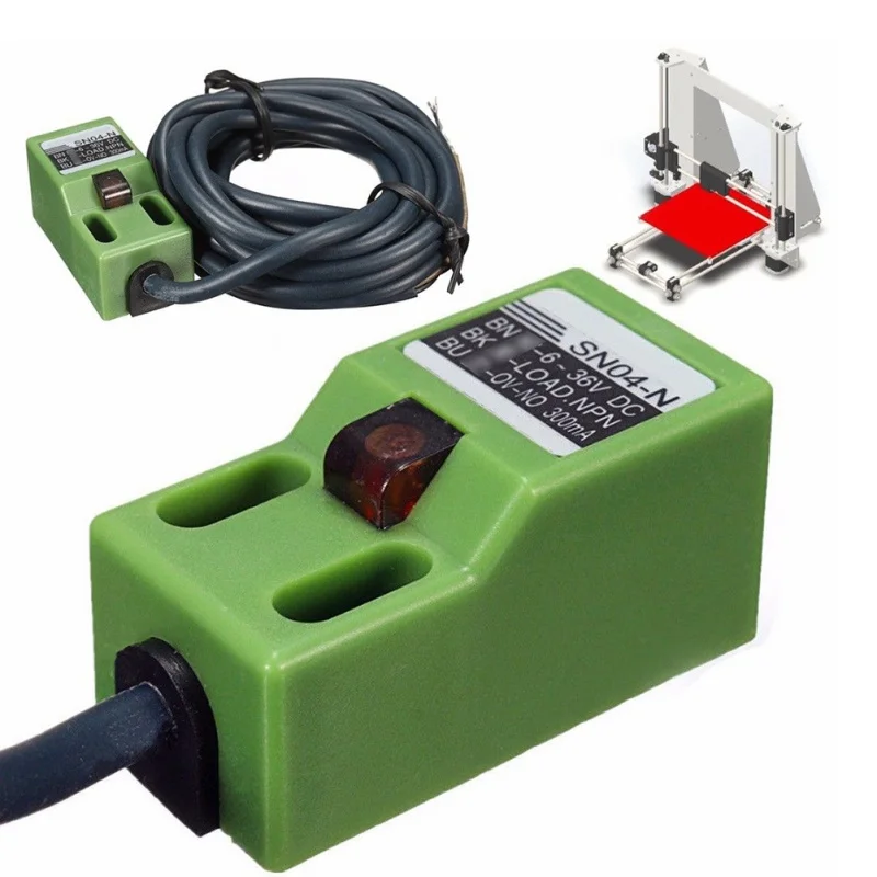 If you're working in a breezy environment, you might also try to shield your printer to keep the wind away from your side.
5) Cause: Platform surface( glue, kapton, glass, etc.)
Solution: Different plastics tend to stick to different better materials. For this reason, many printers include a special material platform build that is optimized for their materials. For example, several printers use a BuildTak sheet on top of their bed, which tends to adhere very well to PLA. Other manufacturers opt for heat-treated glass beds, such as borosilicate glass, which tends when heated to work very well for ABS. If you're going to be printing directly to these surfaces, it's always a good idea to make sure your build platform is free of dust, grease, or oils before you start printing. Cleaning the print bed with a little water or isopropyl alcohol can make a big difference.
If your printer does not include a special platform build material to help with adhesion, you still have options! Luckily, there are several types of tape that also adhere to common 3D printed materials.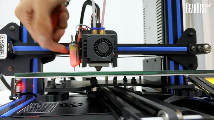 Ribbon strips can be applied to the build surface of the platform and are easily removed or replaced if you need to print with a different material. For example, PLA tends to stick well to blue artist's tape while ABS tends to stick better to Kapton tape (otherwise known as polyimide film). Many users have also had great success using temporary glue or spray on top of their build platform. Hairspray, glue sticks, and other sticky substances tend to work very well if all else fails. Feel free to experiment to see what works best for you!
6) Cause: Raft and Brim
Solution: Sometimes you print a very small part that just doesn't have enough surface area to adhere to the platform build surface. Simplify3D includes several options that can help increase this surface area to provide a larger surface to stick to the print bed. One of these options is called 'edge'. The brim adds extra rings around the outside of your side, much like a hat brim increases the circumference of a hat.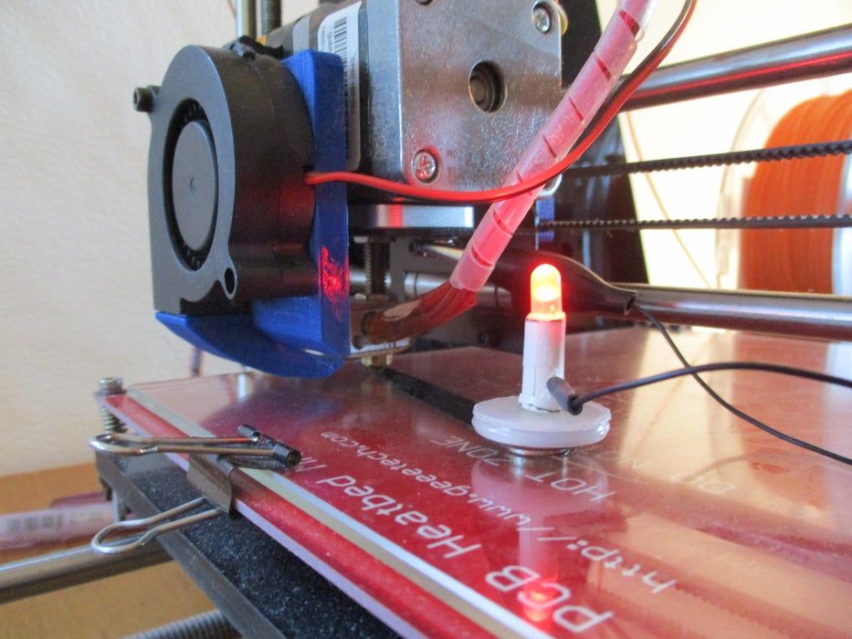 This option can be enabled by going to the 'Receipts' tab at the end to enable the 'Use Skirt/Brim' option. Simplify3D also allows users to add a raft underneath their parts, which can also be used to provide more surface for bed adhesion. If you are interested in these options, please take a look at our rafts, skirts and hem tutorial which explains things in more detail.
So many different reasons for one big problem of not sticking to the table
___________
From www.simplify3d.com
Printer Setup, Slicers, Model Preparation
Part 2 of 'Introduction to 3D Printing', the previous one can be found here:
Introduction to 3D Printing, Part 1
3. Moving on to practice
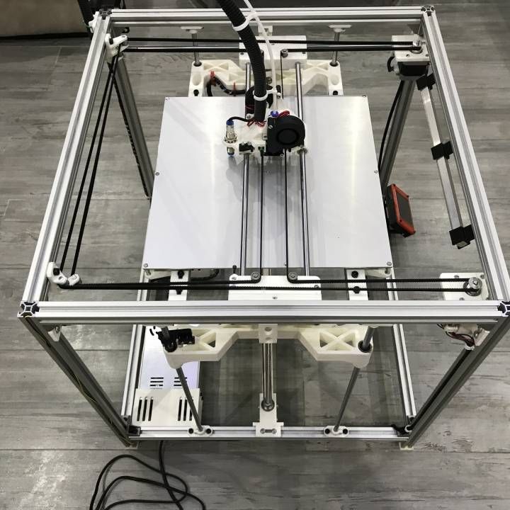
3.1. Unpacking and initial setup
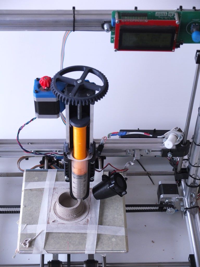
The parcel arrived about a month later, we pick it up, unpack it.
The box contains the printer itself with extruders with 0.4 mm nozzles removed for transportation, two spools of plastic, a small package with spare bolts, nuts and wrenches for working with them, as well as a 4 GB flash drive with test objects. The heated platform has kapton tape and a sticker in English-Chinese, explaining that it is not necessary to remove it.
After assembly, my first thought would be to start printing from the included flash drive, but I found its connector only late in the evening, because printing was done through a computer.
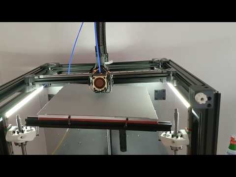
The first thing I tried was to calibrate the heating bed (often called a heated bed, there is no fully established translation here - even I allow the use of both options in the article) using the adjusting screws, but more on that below. Then I connected it to the computer and began to deal with the software.
3.2. First print
The basic “regular” printing program is Repetier Host, by today’s standards, a shaggy version that sees the printer without additional tambourines and allows you to press the “Print” button on a test model downloaded from the Internet without hesitation, which is an elementary cube 2x2x1 cm.
When you press Print, the program thinks about something for a short time, “flashing indicators”, after which the printer comes to life and . .. warming up begins. It turns out that you can't just send something to print. Not only, as you know, printing itself is very slow, but before each print, you have to wait about 7-10 minutes until the heated bed reaches a temperature of 107 degrees. At this time, the printer only buzzes with fans, without producing useful work. When heated, the extruders themselves also warm up, but they take much less time - the slowest camel is the bed.
The printing process has finally begun. First, the printer draws a lattice called a raft on the “bed”, and only after that it gradually prints the original 2x2x1 cm cube on it. The printer plays a melody about the completion of printing, takes the carriage to its initial position, continuing to buzz with cooling PSU and motor fans.
At this point, I again "fall" from the description of the process of mastering the printer directly back into theory.
A raft is usually a double sparse lattice of plastic threads, which is lined up on a substrate before printing on the model itself.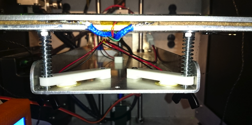 It allows you to partially compensate for temperature loads and the unevenness of the "table", but it greatly spoils the lower part of the model: instead of a flat and smooth bottom surface, you get a set of poorly glued plastic threads.
By the way, the same cube:
The heated bed itself is installed using several (usually four) spring-loaded adjustment screws that allow you to calibrate its level - so that all four of its corners have the same gap between the fully lowered extruder and the very surface of the bed. But no matter how you twist and calibrate them, the heating surface itself is often curved, so at best you'll adjust the corners, the center will almost certainly be concave, or rather concave. I can't guarantee that this is a general trend and not my particular case, but most likely the platform will only be relatively flat, and the center point, located at the maximum distance from the adjusting screws, will also be the most out of the common surface.
This will either cause the extruder to scrape across the table in the center, or if you adjust the center, there will be too much clearance towards the edges, and therefore the contact between the plastic and the table will be mediocre, resulting in delamination (peeling off) edges of the model.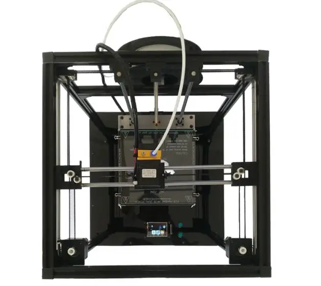 Therefore, for alignment, glass is often placed on top of the heating table. This further increases the warm-up time, but reduces printing problems associated with uneven print surfaces. I will say that it is better to calibrate the platform when it is fully warmed up. at the same time, the gaps will correspond to the real printed ones ... yes, by short twisting the screws with an attempt not to burn your fingers at the same time))
There was also a review where it was recommended to heat the platform longer before printing in order to increase the uniformity of its heating and thus reduce its bending, but I did not personally check the effect of this.
3.3. Slicers
If you are even a little interested in 3D printing, then you know that a slicer is a program for turning a three-dimensional model into a set of commands that the printer understands, called g-code.
Translating a model into an LCD so that the print result is digestible even with a tricky shape of the model is a separate software art in which slicer manufacturers compete. Here I can’t help but recall the famous photograph of Bill Gates, which well describes the generation of this same w-code by the slicer))
Next, I will give a brief description of several popular slicers, so that it is clear what it is, why and in the direction of which names to dig the Internet if necessary. This photo was taken from one of the slicer tests on the internet, and is only shown to illustrate that the LCD generated by different slicers can lead to significantly different results when printed. I do not recommend focusing on this picture according to the principle “this slicer obviously did better”, because this will be highly dependent on specific 3D models and slicer versions.
The printing program that came with the printer - Repetier Host, worked for me on a regular basis with only one Skeinforge slicer that came with it.
So, the main slicers:
1) Slic3r . Perhaps the most popular of today. Constantly being improved. Newer versions are often less stable than previous versions, so despite having 1. 2.9 Stable at the time of writing, the older 1.1.7 is often used , also marked stable. I note that in the new version a lot of changes have been made in terms of the interface, for example, a normally made visualization of the model slicing has appeared.
2) Cura . Also a very popular slicer. It is a complete all-in-one printing system. Convenient "user-friendly" interface, which began to strive for in later versions of Slic3r . I can only say that my communication with this slicer ended with the fact that I could not connect my printer to it without a tambourine, therefore I only used the code generated in it a couple of times. This is not a flaw of the slicer, but only my experience with it.
3) Kisslicer . Even shorter: relatively popular, but I did not work with him at all, therefore I cannot give a description.
4) Skeinforge . About it, you can limit yourself to the fact that its support was discontinued a few years ago, so I do not recommend using it except for the case “it comes with the kit, you need to print it now without setting anything up”.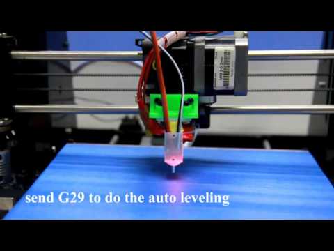 I mentioned it here only because it was the first slicer that worked without problems with my printer.
I agree, the description of the slicers turned out to be a bit strange and too indetailed. I proceeded from the principle of reasonable sufficiency: if a given slicer performs its work no worse than another according to the results of several tests, then I take the one that is more convenient for me and work with it until the information appears that “this one is clearly better” . This will not give the best result, but it will allow you to devote reasonable time to the technical aspects of printing, without moving, as I said above about homemade printers, into an excessive cycle of self-production. As a result, I settled on Slic3r and use it to this day. This article does not aim to accurately describe and compare the work of all slicers, so I will leave the selection of a slicer for your individual goals and objectives.
The slicer itself is put into operation either at the moment the object is sent for printing, or, as they often do now, slicing is carried out right in real time immediately after loading the model.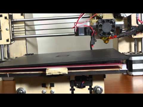 In fact, on modern computers, the time for a slicer to convert a model into a f-code is short enough not to mention it separately with a phrase like “after two hours of slicing, the model was still ready for printing.”
Also, I do not give here any specific settings for specific slicers, but below in one of the chapters I will give a few common ones for all of them.
3.4. Preparing the Model
After I had already made several printouts of test cubes and various pyramids and polygons with round holes, I wanted to print something specific. I took a model of a smelting furnace with a slag spill conveyor that I once made and, without much thought, sent it to print.
At this point, seasoned 3D printers burst into Homeric laughter, because the whole lamerism of trying to print such a model without the slightest preparation on the face, but, as I said above, this model was sent for printing only out of interest and after a couple of hours of getting to know the printer.
Although I turned on the automatic generation of supports, after two hours it became clear that there would be nothing worthwhile in the output. Parts of the conveyor are too thin for printing at this scale, some of which are generally hanging in the air, which, due to their thinness, cannot be saved by any generated calipers. As a result, I got a bunch of tangled threads, in which in some places the outlines of the conveyor racks and the frame of the boot block were guessed. So I got acquainted with the need to prepare the model for printing.
And again an excursion into the theory. As I already wrote in the article about the layout of the church, I divided all 3D printing for myself into two ideological approaches: engineering and design. The first relates to working with printing gears, fasteners and spare parts for a new printer, RC models or some other mechanical structures, while the second is responsible for printing the statue of Zeus, brick walls with windows and all sorts of scale models of something (for example, any statue - This is also a scale model.
This division is rather conditional, but at the same time real. Gears and mechanical assemblies are easiest to do in the software designed for this, the same SolidWorks , Compass 3D and others. At the same time, you make your entire model with holes, chamfers and elements of bodies of revolution, after which you export everything to a stl file, open it in a slicer, and then it will convert the model into an LCD without requiring additional intervention from you.
At the same time, an attempt to make in the drawing program a spaceship, a statue of Buddha, or the same brick wall of a building in which each individual brick stands out from this wall will end up in a quite predictable time for developing such a model to infinity, which is equivalent to the effective impossibility of creating such models. And in general, do you represent a drawing of a Buddha statue in solid? Here I am, no)) There are completely different programs for such things - for example, ZBrush or MudBox for sculptures or the same great and terrible 3DSMax for everything else.
Engineering programs are initially designed to work with curved surfaces, chamfers and other elements of three-dimensional design and are usually able to produce a printable result on the mountain - a mesh (this is the name of an object consisting of triangles) with good topology, but the same 3dmax when you make, for example, a brick wall, when you try to combine it into a single non-intersecting mesh using the Boolean -> Union operation, you are guaranteed to get an unusable result. More precisely, most likely you will get a void instead of an object. And I'm still considering the simplest case, sometimes topology errors are not visible to the naked eye, but the model will be unusable for printing. The bottom line is that 3dmax, despite the fact that this is a program for working with three-dimensional space, is not suitable for working with volumes. Being originally sharpened to work with triangles hanging in the air, it remains fundamentally so to this day.
Before saying what model preparation is, you first need to pay attention to the file format used today for printing STL . This format contains a model by writing it in separate triangles, when, for example, a cylinder is divided into many “faceted” segments, which ultimately reduce to these same triangles. Those. there are no curved surfaces, spheres and tori, like spoons from the Matrix, all objects are approximated into figures consisting of a bunch of triangles. Couldn't resist a little easter egg in the picture.
The slicer reads triangles from the stl file, cuts this set into thin layers, which as a result turn into the paths of the print carriage. As long as you are dealing with a correct mesh, there are no problems, but as soon as a hole appears in it or the intersection of triangles, the slicer may start to “stutter”. And this is not always exactly a “mistake”, it’s just that the slicer must know exactly how to interpret your model. And if one of the edges of your box is missing, does this mean that it simply should not have one wall and it should be completely hollow and thin-walled, or should this hole be closed automatically and the box be considered whole. This is the simplest example, and there are a lot of situations with a completely incorrect grid, when it cannot be printed correctly at all.
Now let's talk about the preparation of the model itself. If above there was a long boring theory about the topology of the model and its export to stl format, the practice itself in the description is much simpler: only the preparation work itself is long in it.
1) The item is relevant for design programs (read 3dmax). The model must have the most correct mesh possible during the initial export. That is, if you make a model for printing in the same max, make sure that, if possible, it does not have open edges (holes in the grid), triangles intersecting in one element and similar indecencies. The model recovery system will most likely fix this, but it's best to keep the risk to a minimum.
2) Relevant for everyone. Complex or large models need to be divided into elements, because. it is either impossible to print in one go, or the result will be noticeably lower quality than printed correctly in several parts, and then glued together.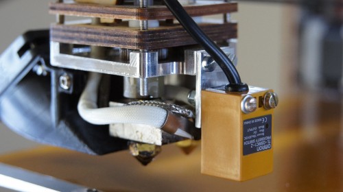
3) Correct location of the model. The lower the height, the faster the model prints - the total print speed in height is always lower than the print speed of the layers themselves ... I understand that the wording is not very good, but you can understand))
4) Specific practical advice buried in a pile of theory)) Run the model through model recovery system. Firm Netfabb is one of the developers of such systems. Company Microsoft bought this technology and made a free service for restoring models in the cloud. For design printing, this is a must have. Register an account if you don't have one, and run the model through the service at https://netfabb.azurewebsites.net/
Run through the restore service is primarily needed for models exported from max, made in the style of "a bunch of intersecting boxes", for programs exported from CAD, this is necessary only sometimes, when the program during export could not make the correct topology. However, this often happens.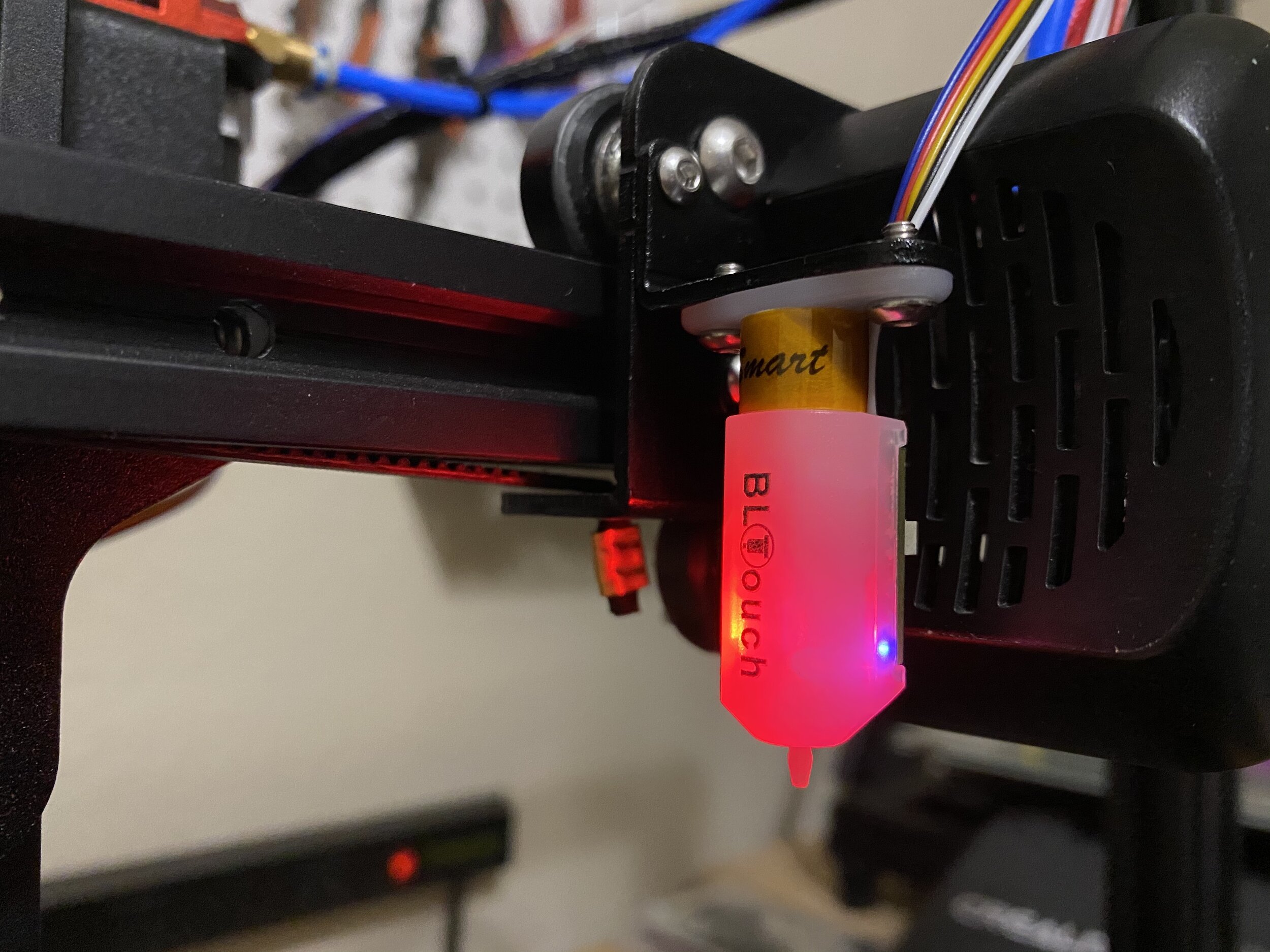
After processing on this or similar service, the model is ready to be sent to the slicer and printed.
3.5. Some Features of Model Making
I'm going to be a bit inconsistent here and go back to the stage when you're still painting or about to remake your model for printing.
I noticed for design printing. Such printing is usually associated with printing the product in some scale, but when no one will sit with a caliper, measuring out the exact size.
At its simplest, you want to print railings for the roof of a building. In real life, they have a thickness of about 4-5 cm, but with a print scale of 1/80, you will get their diameter of about 0.5-0.63 mm. Given the nozzle of the printer (in my case 0.4 mm), they will be either 0.4 or 0.8 mm if we print in two perimeters. I will say that print them with a thickness of 1 perimeter, i.e. 0.4 mm would be completely unreasonable - for ordinary ABS plastic, such a thickness is too “openwork”, plus it will be very difficult to glue them on the building.
The same goes for any object that should be solid or at least solid after printing. My attempt to print the conveyor racks shown a few pages above, which are only a millimeter or less thick on scale, and the conveyor belt itself, which is about a centimeter thick in real scale and about a quarter of a millimeter thick in print scale, is a good example of this. The scale of objects must be realistic for printing.
A couple of things about engineering printing. When you print a cylinder with a diameter of 10 mm and a hole for it 10 mm, then, of course, the cylinder will not enter this hole, because. no tolerances for the correct fit of this cylinder will be observed. There are several reasons:
1) Inaccurate operation of the printer mechanics, due to which each subsequent layer can be stacked with a slight arbitrary offset. As a result, this reduces both the diameter of the bore and increases the diameter of the cylinder itself.
2) Thermal expansion on heating and therefore shrinkage on cooling.