Inventor 3d print
Using Inventor for 3D Printing | Search
View Original X
Products and versions covered
Inventor Products, Factory Design Suite, Plant Design Suite, & Product Design Suite
Ronald Jones, Sr. Solutions Engineer
Ronald Jones
Sr. Solutions Engineer
94 contributions
- 98 posts
- 68 kudos
- 9 solutions
- 6 ideas
REPORT
Report this article?
CANCEL REPORT
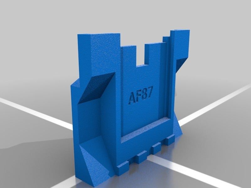
Inventor and 3D Printing
3D printing is quickly becoming the standard for prototyping. It’s cheaper, faster, a heck of a lot easier then manufacturing a part, just to find out that hold needs to be 5 thou bigger. Trust me we’ve all been there. Remembering back to the old days of Inventor, trying to create a 3D print of your model was difficult. There was file exporting, waiting, and sometimes even some profanities. The tides have changes though, with advancements in additive manufacturing and 3D printing Autodesk has included a tool in Inventor that allow us to quickly generate the mesh file we need for our 3D printers, and even send a file directly to the printer for use.
Where’s the Tool At?
I’m referring to the 3D Print tool inside of Inventor. Not the American rock band. This tool is easy to find, navigating to the Environments panel we are greeted by an image of a 3D printer towards the middle of the page. Clicking on this tool launches a representation of a print bed. This tool is designed to work natively with an Autodesk Ember printer, or a number of other 3D printers. From this environment, we can now set the orientation of our part, do some direct modeling if say we need to make it a bit longer, or even insert work planes. This is where it really gets cool, users have the ability to send this part over to Autodesk Print Studio or even Meshmixer. Users also have the ability to send this print directly to their printer. Utilizing the Print Options tool, you can refine your mesh structure, units, and even color.
Prototyping Out of Plastic?
With 3D printers becoming more and more affordable and cramming more technology into a smaller price tag, this new way of thinking almost sells itself. Thinking back to my days in industry our department literally had an entire area dedicated to machines we needed to machine and manufacture prototypes. These lathes, mills, and saws could be replaced with one 3D printer that takes up a heck of a lot less space and time. Prototype creation can take hours of your time cutting chips on a mill. Where as 3D printing only takes a few minutes and hitting the “Go” button. Errors can be caught earlier and normally cost less to revise, seeing as you only have a plastic part and not a full blown metal prototype. 3D printing is the future of making things, and Autodesk Inventor is at the forefront of this technology.
How can I use it for Non Native Inventor Files?
Utilizing Autodesk's AnyCAD technology that is housed inside of Inventor, users can use non-native Inventor files to create 3D prints. AnyCAD can open Solidworks, Creo, Catia, Solidedge, and NX files natively. Opening a Catia file for example for launch the AnyCAD menu, Converting the file into an Inventor part will complete the interaction with AnyCAD. From here users can use the same 3D printing tools described above. Users could even import a 2D DWG into Inventor, complete an extrude or revolution command to make it 3D then print it using the 3D print Enviroment in Inventor.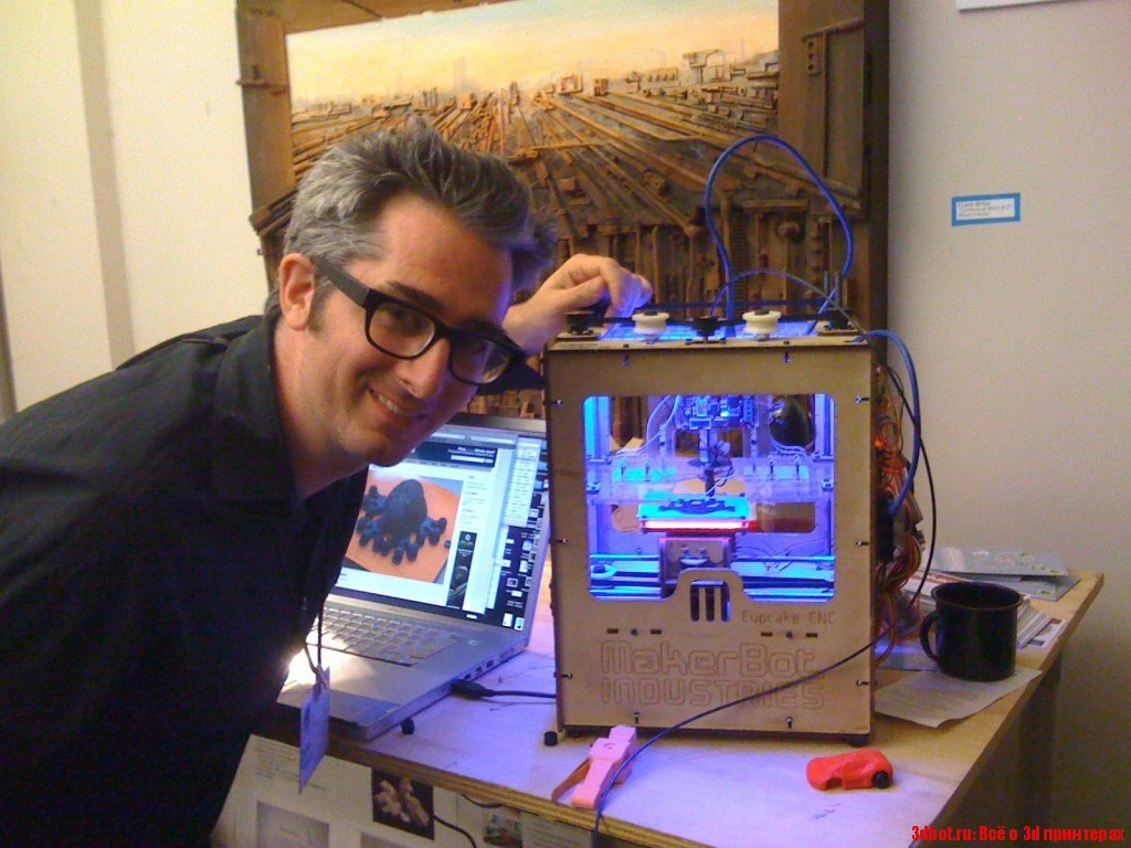 This means that a file can be created in any number of CAD packages then translated and printed using Autodesk Inventor. For more information on AnyCAD please visit: http://blog.advancedsolutions.com/topic/manufacturing/inventor-2018-part-2
Summary
Manufacturing and design is quickly evolving and changing, prototypes that use to be made out of metal and machined on a lathe or mill, are now being printed in a few hours and for a fraction of the cost of their metal ancestors. Using Inventor for 3D printing allows users to design a protype in canvas from Inventor, eliminating the need for 3rd party programs and exporting Inventor files to any number of "generic" CAD formats. Another benefit of this, is the ability to make changes quickily. Because everything is inside of Inventor a quick change to the part doesn't warrant exporting and transferring to another program. This saves valuable time allowing the user to create a new 3D print with just a few clicks. The Future of Making Things is evolving rapidly, Inventor gives the flexibility to stay ahead of the curve.
{{l10n_strings.ADD_DETAILS_PROMPT}}
{{l10n_strings.SELECT_A_COLLECTION}}
{{l10n_strings.ITEM_ALREADY_EXISTS}} {{l10n_strings.ITEM_MAX_REACHED}}
{{l10n_strings.CREATE_NEW_COLLECTION}}
(* {{l10n_strings.REQUIRED_FIELD}})
{{l10n_strings.CREATE_NEW_COLLECTION}}*
0 / 80
{{l10n_strings.ADD_COLLECTION_DESCRIPTION}}
{{l10n_strings.COLLECTION_DESCRIPTION}} {{addToCollection.description.length}}/500
{{l10n_strings. TAGS}}
{{l10n_strings.PRODUCTS}}
{{$item.Name}}{{l10n_strings.DRAG_TEXT}}
{{l10n_strings.DRAG_TEXT_HELP}}
{{l10n_strings.COLLECTION_CATEGORIES}}
{{l10n_strings.GETTING_STARTED}} {{l10n_strings.LEARN_EXPLORE}} {{l10n_strings.TROUBLESHOOTING}}
{{l10n_strings.LANGUAGE}}
{{$select.selected.display}}{{article.content_lang.display}}
{{l10n_strings.AUTHOR}}
{{l10n_strings.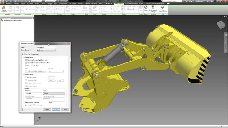 AUTHOR_TOOLTIP_TEXT}}
{{l10n_strings.CREATE_A_COLLECTION_ERROR}}
{{l10n_strings.CONTRIBUTION_ADDED_TO_COLLECTION}} {{addToCollection.collectionTitle}}.
How to Prepare STL Files | Stratasys Direct
How to Prepare STL files
STL is the standard file type used by most additive manufacturing systems. STL is a triangulated representation of a 3D CAD model. Below you will find instructions on how to convert CAD to STL for many popular platforms.
The triangulation (or poly count) of a surface will cause faceting of the 3D model. The parameters used for outputting a STL will affect how much faceting occurs (Figures 2 and 3). You cannot build the model smoother than the STL file. If the STL is coarse and faceted the physical 3D printed model will be coarse and faceted as well.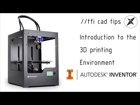 However, the smoother/ less faceted your surface is, (the higher the poly count or triangulation) the larger your file. 3D printing can only accept a certain file size; therefore it’s important to find a balance between your model, its desired surface, and the 3D printing process of your choice.
An example of course triangulation.
An example of fine triangulation.
Your other option is to skip the process below as we offer instant quoting using just your native CAD file.
Simply sign-in, upload your CAD file(s), make your desired selections, click order, and get parts as fast as 2 days!
Yes, it is that easy.
Upload Native CAD here
When exporting to STL in your CAD package, you may see parameters for chord height, deviation, angle tolerance, poly count, or something similar. These are the parameters that affect the faceting of the STL. We’ve compiled tips on exporting for the best “surface: file” size ratio below.
Preparing your files
The following step-by-step instructions for converting CAD files to STL came from each CAD software company’s website or from 3D printing and design user forums; it’s an overall simplified step-by-step process from the greater 3D printing community. If your CAD software is not listed below or if you require additional assistance, please contact your CAD software technical support for information about exporting to an STL.
The CAD softwares covered below:
3D Modeling for Beginners
- Tinkercad
- SketchUp
3D Modeling for Engineers
- Autodesk Inventor
- CATIA
- IronCAD
- Rhinoceros
- PTC Creo Parametric
- Solid Edge
- SolidWorks
- NX
3D Modeling for Artists
- Blender
- ZBrush
- Maya
Don't have CAD software? SolidView is an affordable solution for non-CAD users to prepare STL files from many popular CAD formats. Start your free trial today.
Tinkercad
You can also just load your native CAD into our online quoting tool to get instant pricing!
Tinkercad is great for 3D printing simple geometrical objects. Its interface was created with 3D printing in mind.
- Design > Download for 3D Printing > .STL
SketchUp
You can also just load your native CAD into our online quoting tool to get instant pricing!
SketchUp does not offer STL creation directly within the program. Download the extension for .STL here (note: this plugin is open-source and updated frequently).
- Download and install the plugin
- Select Tools > Export to DXF or STL and select the units for your model (millimeters is recommended)
Tip: SketchUp isn’t inherently built for model production therefore it’s useful to check your SketchUp file for additional feature accuracies once it’s exported from the interface. We recommend uploading your SketchUp file into Meshmixer (a free program from Autodesk) to check your file for faceting and fix any surface flaws.
Note: We don’t recommend Sketchup for use with 3D printing as it does not export well and is best for early design sketches rather than producing physical models.
Autodesk Inventor
You can also just load your native CAD into our online quoting tool to get instant pricing!
-
-
- Select IPro > Print > 3D Print Preview
- Select Options and choose desired resolution and click OK
- Within the preview window, select Save Copy As or Send to 3D Print Service
- Save As type to STL File (*.stl)
-
Note: The “High” setting will also produce the largest file size. From Low, Medium to High, the hairdryer sample file in Inventor went from about 6.7MB to 17.6MB to 50MB.
Tip: Before finalizing your export, select the Options tab. Within this window, you can select the resolution (faceting) for your model (High, Medium, Low and Custom) and check that your units are correct. The “High” setting will produce a large file size. Autodesk Inventor allows you to save both individual parts and assemblies in STL format, at all design levels. For a quick overview of designing in Inventor, click here.
To check your modifiers have been applied before exporting:
- Tools > Rebuild All (this ensures that the design data contains recent changes, and that it is not corrupt)
- File > Save Copy As > STL (.stl)
- Select High and click OK
Note: To change the values associated with each of the resolution settings (High/Medium/Low) you need to edit the Windows registry.
CATIA
You can also just load your native CAD into our online quoting tool to get instant pricing!
- Select STL command (we recommend setting maximum segmentation to 0.015 mm)
- Select the model > Yes > Export
Note: CATIA V5 is capable of creating STL files from CATPart files, but not from assemblies (CATProduct files) or geometrical representations (car files). Therefore, source files, including those saved in a neutral format (i.e. STEP or IGES), must be saved as CATParts. If the source design was saved as an assembly, it is imported to CATIA as a CATProduct. To create an STL file from it, you must first convert it to a multi-bodied part. The procedure described below is one of several methods for doing this.
Saving CATProduct files as CATPart Files for 3D printing:
- File Menu > Open > select your source file (assemblies import as CATProduct)
- Save the imported CATProduct file
- Select File > New > Part > Name the new part
- Select one component from your master CATProduct File and copy it
- Paste the component in a new part window
- Repeat steps and until you have copied all of the components and pasted them as individual parts
- Once you have the assembly completely separate into individual components, select File > New Part
- Copy each of the individual components from the working files and paste them into the new combined model file (the geometries of all of the parts should retain and align correctly in the combined part)
- The new part is now ready to be exported as an STL file
- Select Tools > Generate CATPart from Product
- Finally, Select File > Salve As > Save as type: STL
Tip: Occasionally some of the components may not align correctly in the combined part because of the way the original assembly was designed. To align parts, select Insert Menu > Constraints Feature.
Before saving the file, it is advisable to review the settings that determine model accuracy and file size. To see these parameters:
- Tools > Options
- In the Options dialog box, display the Performance tab
- Under the General category (on the left), select Display
- Review 3D Accuracy settings
Tip: Curves’ accuracy ratio: The higher the setting, the smoother the surface will be when dealing with complex geometries, especially if surfaces contain sudden small changes with small radii (like the bumps on a golf ball).
IronCAD
You can also just load your native CAD into our online quoting tool to get instant pricing!
- Right-click on the part
- Click Part Properties > Rendering
- Set Facet Surface Smoothing to 150
- File > Export
- Select .STL
Note: IronCAD can export in many file formats depending on your geometry.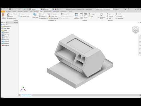
Tip: When working in assembly mode, you must save each of the component parts as individual STL files. The procedures for doing so are described below.
Saving a model design in STL format:
- Open the model design in IronCAD.
- Right-click on the part and select Part Properties > Part dialog box
- Make sure that the Rendering tab is displayed
- Change the Surface Smoothness setting to an appropriate value for your model.
- If you have not established an appropriate value, try 150. The higher the number, the smoother the model surface will be.
- Change the Max Edge Length setting to an appropriate value for your model.
- If you have not established an appropriate value, try 0.05. This setting produces good results, but increases file size and may require several minutes to render the model to STL format.
- To create smoother model surfaces when designing spherical and torus geometries, select the Triangulated Mesh check box.
 Selecting this check box results in larger STL files, but may produce smoother curves in models. If the surfaces of the model design are planes, this setting does not improve the results.
 - Click OK to save the settings and close the dialog box.
- File > Export > STL
- In the Stereolithography dialog box, make sure PC is selected, and select the Binary Output check box.
- Click OK to save the settings and create the STL file.
Rhinoceros
You can also just load your native CAD into our online quoting tool to get instant pricing!
- Select Object
- Mesh > From a NURBS Object
- Select Polygon Mesh > Detailed Controls
- Maximum aspect ratio: 2.0
- Perspective > Rendered View > Observe smoothness and confirm it meets standards
- To check that your mesh is uniform: Select the new object mesh > Analyze > Mass Properties > Volume
Rhinoceros 4
- File > Save As
- Select File Type as STL
- Select File Name > Save
- Select Binary
- Select Detail Controls from Mesh Options
- Max angle = 20, Max aspect ratio = 6, Min edge length = 0.
 0001
0001 - Click OK
Tip: Check your objects geometry and surface in the Object Properties tab to ensure object uniformity.
Rhinoceros Version 3 and Later
Rhinoceros enables extensive control of STL properties when saving designs as STL files. Because Rhinoceros software is surface-based, the complete model design (even if an assembly) is saved as a single STL part.
Saving a model design in STL format
- Select Part > File > Export Selected > In the Save As Type box, select Stereolithography (*.stl)
- Click Save
- In the STL Mesh Export Options dialog box, set the STL tolerance – the maximum distance allowed between the surface of the design and the polygon mesh of the STL file.
- If you do not know the other settings appropriate for your model design, try these:
- Tolerance: Less than half of the printer’s resolution. For example, the setting shown in the figures above (0.01 mm) is a good setting for printing models at a resolution of 0.
 03 mm
03 mm - Maximum Angle: Default
- Maximum Aspect Ratio: Default
- Maximum Edge Length: Clear
- Maximum Edge Length: Clear
- Maximum Initial Grid Quads: Default
- Refine Mesh: Check
- Pack Textures: Check
- Click OK
- In the STL Export Options dialog box, set the file type as Binary and click OK
- Note: If the Export open objects check box is selected, STL files will be created for each of the objects currently open. If this check box is cleared, an STL file is created for the selected object.
- In the STL Export Options dialog box, set the file type as Binary and click OK
- Tolerance: Less than half of the printer’s resolution. For example, the setting shown in the figures above (0.01 mm) is a good setting for printing models at a resolution of 0.
- If you do not know the other settings appropriate for your model design, try these:
Important: STL files are suitable for 3D printing if the models they describe are “watertight”, that is, they do not contain holes or gaps. If an error message appears, click Cancel and fix the model design before saving it as an STL file. Steps for fixing mesh in Rhinoceros are detailed below.
Troubleshooting Model Designs
If a model design contains holes or gaps, it is not suitable for 3D printing.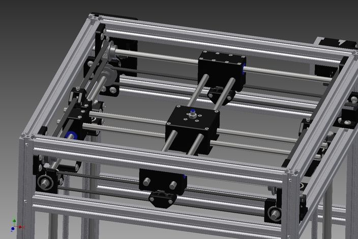 Before saving it as an STL file, you must make it “watertight.”
To close holes and gaps in a model design:
- Check your object for errors: Command = Checknewobjects
- Surface errors will display
- Delete problem surfaces: Command = Selbad
- Command: Rebuildedges
Analyze Naked Edges:
- Analysis > Show Edges/ Edges Off > Command = Showedges
- Select object > Enter
- Within dialogue box, select Naked Edges
- Highlighted lines are naked edges and must be joined to the rest of your model
Fix Naked Edges
Option 1:
- Command = _Mesh
- This will create a mesh from the NURBS geometry (save your original NURBS file before doing this)
- Command = _Showedges
- This will detect naked edges
- Command = Fillhole
- If you cannot find the Fillhole command, open your Tools tab and select Toolbar Layout
- From the menu, check the box for Bonus Tools
- The Bonus Tools window will open
- Select Fill Mesh Hole
- If you have trouble, make sure you have the right updates installed
Option 2:
- Click the Mesh from Surface/ Polysurface icon from toolbar
- Polygon Mesh dialogue box will open
- Click Detailed Control > Polygon Mesh Detailed Options dialogue box will open
- Enter desired settings > OK
- Select entire object
- Tools menu > Polygon Mesh > Weld
- Command = 180 for angle tolerance
- The Weld command will merge adjacent triangle points when 180 angle tolerance is set
- Validate the object is watertight
- Command = SelNakedMeshEdgePt
- If the resulting object contains holes or gaps, the mesh needs fixed
- Repeat the Save As procedure
PTC Creo
You can also just load your native CAD into our online quoting tool to get instant pricing!
3D printing in PolyJet:
- File > Print > 3D Print
- Define Material
- Define STL resolution
- Tip: Check your file for printability through the Printability Validation Tab
Retired PTC Creo Formats: Pro/ENGINEER
- File > Export > Model
- Set type to STL
- Set chord height to 0.
 The field will be replaced by minimum acceptable value
 - Set Angle Control to 1
- Click OK
Exporting your STL file can be done at all levels of design, for both individual parts and assemblies. When dealing with assemblies, you can specify parts of an assembly to either include or exclude from the resulting STL file. Use the procedure below for saving both parts and assemblies as STL files for eventual 3D printing.
To save a Pro/E as an STL file:
- Check that the model design is continuous and “watertight”
- This step is especially important if the design was imported from a neutral design format because non-continuous bodies are likely to result in defective models
- To check for continuity:
- View the model with hidden lines displayed.
- From the View menu, select Display Setting > Scheme > PreWildfire. The model surfaces are displayed in magenta. If the design is continuous, the contour lines are white. If there are gaps, the lines are yellow.
- Fix the model design, if necessary, before saving it as an STL file.
- From the File menu, select Save a Copy. The Save a Copy dialog box appears.
- From the Type pull-down menu, select STL
Deviation Control
The Deviation Control settings in the Export STL dialog box affect the accuracy of the model and the size of its file.
- Open Chord Height (chordal tolerance)
- This setting specifies the maximum distance between the surface of the original design and the tessellated surface of the STL triangle (the chord)
- Chord height controls the degree of tessellation of the model surface
- The smaller the chord height, the less deviation from the actual part surface (but the bigger the file)
Angle Control
This setting regulates how much additional tessellation occurs along surfaces with small radii. The smaller the radii, the more triangles are used. The setting can be between 0 and 1. Unless a higher setting is necessary, to achieve smoother surfaces, 0 is recommended.
Once you have reviewed the above the controls and adjusted your settings, click Apply > OK to create the STL file.
Saving a Pro/E Assembly as an STL File
- File > Save a Copy
- From the Type pull-down menu, select STL.
- Export STL dialog box appears: Specify the parts of the assembly to either include or exclude within the resulting STL file
- Example: In the dialog box one of the parts of the assembly (the tire) has been excluded, leaving two parts (the hub and the main wheel) to be exported to the STL file. The design resulting from these settings (when you click OK) is shown on the left.
- When you have made all of the required settings, click Apply and OK to create the STL file.
Solid Edge ST6 - ST8
You can also just load your native CAD into our online quoting tool to get instant pricing!
- Application Button > Save As (opens dialog box)
- From the Save As drop down menu, select STL documents (*.
 stl)
stl) - Select the Options button from the Save As dialog box
- Adjust Conversion Tolerance and Tolerance Units (millimeters recommended)
- The lower the conversation tolerance, the finer the tessellation
- Adjust the Surface Plane Angle (dependent your desired surface smoothness)
- The lower the surface plane angle, the greater the accuracy (noticeable in small details)
- As a rule, the finer the tessellation and the greater the accuracy, the larger the size of the STL file, and the longer it takes to generate it
- The lower the surface plane angle, the greater the accuracy (noticeable in small details)
- Under Output File as: Check Binary
- Binary STL files are much smaller than STL files saved in ASCII format
- Click OK > Save
Tip: Review the controls for exporting STL files in Solid Edge here.
Note: Solid Edge is capable of creating individual STL files from the components of an assembly, but this functionality is not built into the program. It is achieved through the application programming interface (API), using Visual Basic scripts.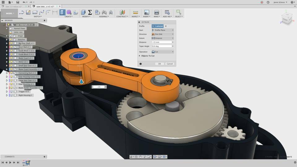 This solution does not enable a visual preview of the polygon mesh before saving the STL files.
Solid Edge (Older than ST6)
- Open model and select File > Save As
- Save As Type >STL
- Options > Conversion Tolerance: 0.0254 mm for FDM; 0.015 mm for PolyJet
- Set Surface Plane Angle to 45°
- Select Binary type and OK
- Name and Save STL file
Note: Solid Edge software from Siemens PLM (formerly USG) supports STL output at the core level, enabling you to save both parts and assemblies as STL files. However, when saving an assembly, all of its components are included in a single STL file.
SolidWorks
You can also just load your native CAD into our online quoting tool to get instant pricing!
- File > Save As
- Set Save As Type to STL
- Options > Resolution > Fine > OK > Save
STL settings: How to change STL settings
- File > Save As
- STL > Options
- For a smoother STL file, change the Resolution to Custom
- Change the deviation to 0.
 01 mm
01 mm - Change the angle to 5 (smaller deviations and angles will produce a smoother file, but the file size will get larger)
Tip: Review file export options before you save your file from SolidWorks here.
To save a model or a model assembly in STL Format:
- File > Save As (Save As dialog box opens)
- From the Save as type drop-down menu select STL (*.stl)
- Click Options
- The Export Options dialog box will display the file in a tessellated view
- File Format selection is STL
- In the Export Options dialog box > Output As section select Binary
- The resulting file size will be much smaller than a file saved in ASCII format
- In the Resolution section, select the appropriate option
- If you select Custom, you can manually adjust the Deviation and Angle settings
- The Deviation and Angle settings affect the tessellation of non-planar surfaces as follows:
- Lower deviation settings result in finer tessellation
- Lower angle settings result in greater accuracy, noticeable in small details
- Note: The higher the resolution, the larger the size of the file, and the longer it takes to generate
- For single material builds make sure that the following check box is selected: Save all components of an assembly in a single file
- This ensures that all components are saved as a single STL file.
- This ensures that all components are saved as a single STL file.
- For dual material builds (PolyJet) make sure that the following check box is NOT selected: Save all components of an assembly in a single file
- Note: Keep in mind that an assembly with many units will create many individual STL files when the “Save all components of an assembly in a single file” check box is left unchecked
- Click OK
- In the Save As dialog box, click Save
- In the confirmation message, click Yes
NX (Formerly UGS NX)
You can also just load your native CAD into our online quoting tool to get instant pricing!
NX software from Siemens PLM (formerly USG), supports STL output at the core level, enabling you to save not only entire parts as STL files, but also selected surfaces of a part. This gives you great flexibility when preparing objects for 3D printing. In addition, assembly output enables you to save several components as a single unit while maintaining each component as a separate volume (shell).
- File > Export > STL
- Rapid Prototyping dialogue box will appear
- Output Type: Binary
- Binary STL files are much smaller than STL files saved in ASCII format
- Triangle Tolerance: 0.015 mm
- This is the maximum distance allowed between the surface of the original design and the tessellated surface of the STL triangle, and affects the smoothness of the model surface
- Adjacency Tolerance: 0.015 mm
- This determines if two adjacent surfaces “attach”. If the distance between the two surfaces is less than this setting, they are considered attached. This setting must be less than the printing resolution. For example, when printing models at a resolution of 30 micrometers (microns), the setting must be no more than 0.03 mm.
- Auto Normal Gen: Check box
- Normal Display: Check box
- Triangle Display: Check box
- Click OK
- Export Rapid Prototyping dialogue box will appear
- Name your file and click OK
Blender
You can also just load your native CAD into our online quoting tool to get instant pricing!
Prior to exporting, ensure your object is uniform by checking that all surfaces/ vertices are connected.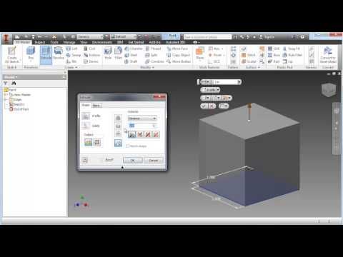
To check your file for uniformity:
- Enter Edit Mode, select your object, and press “L” over the mesh
- Areas that do not highlight are free-floating. All vertices must be connected for your part to print.
- After you’ve confirmed your object is uniform, check for holes in the mesh of your part
- Enter Edit Mode, deselect all vertices, and select Non Manifold from the drop down menu or simply hit Shft-Ctrl-Alt-M
- Change the units and dimensions of your object
- Blender’s default measurement is called a Blender Unit and is equal to one meter
- Press “N” to bring up your dimensions tab
- Change units from Blender Units to Metric by selecting Properties > Scene Tab
- Change units to Metric (preferably millimeter)
- Adjust your scale within the dimensions tab to compute with Metrics
Now your file is ready for export.
- Select File > Export as .STL (* .stl)
Tip: Modifiers can be applied during export or prior.
ZBrush
You can also just load your native CAD into our online quoting tool to get instant pricing!
ZBrush provides designers with incredible feature capabilities, however those features equate to thousands of tiny polygons that aren’t always feasible for 3D printing. To ensure your part is producible and that its details resolve as desired, download the Decimation Master Plugin from ZBrush.
The Decimation Master Plugin will allow you to optimize the polygon mesh of your part for printing by specifying a percentage of the poly mesh to preserve for export. It will preserve detail while reducing poly count. For a quick overview of the plugin, including masking to preserve areas where high poly count is critical for your model, click here.
Once you have optimized your part using the above steps, it is ready to export as an STL file.
- Download the 3D Print Exporter Plugin from ZBrush
- Select the ZPlugin menu
- Click 3D Print Exporter
- Define and scale your dimensions
- Select STL > STL Export
- Save
Maya
You can also just load your native CAD into our online quoting tool to get instant pricing!
Maya is a free-form design space not specifically tailored to production, therefore it is especially crucial to check the dimensions and producibility of your design (are the wall thicknesses defined? Are all vertices connected?).
Check features for producibility:
- Window > Settings > Preferences >Settings
- Change measurement units to millimeters
- Review dimensions and scale within the Chanel Box
- Finally, open Create > Scene Assembly
- Access measurement tools to check all feature sizes and thicknesses
Once you’ve checked your part for producibility, open the Rebuild Surface Options and define the surface density of your part. This will determine the resolution of the final 3D print. Check the design guidelines of your preferred technology to ensure the 3D print process can handle your desired resolution. Design guidelines on each 3D printing technology can be found here.
Now you’re ready to export.
- Select File > Export Selection > Export as STL_DCE.
How Chuck Hull Invented 3D Printing / Habr
3D printing was born in 1983, long before people began to massively use the World Wide Web. But the Internet has long become an ordinary part of life, and additive technologies still cannot be called widespread.
At the same time, Chuck Hull, the inventor of 3D printing, believes that we have already passed the period of hype and are only now beginning to understand the real field of application of the technology. This post is about how Chuck (Charles) Hull invented and patented laser stereolithography in a small utility room and how he now evaluates his invention.
Spoiler: like industrial robots, the automotive industry has greatly helped the development of 3D printing.
Table tops and prototyping
It all started in the 80s. Then Chuck worked as a technologist in California Ultra Violet Products. The company produced UV curing resin for countertops. There was no question of high speed of work - it took months to develop and test even small details. Chuck's responsibilities, as responsible for organizing the production process, included prototyping.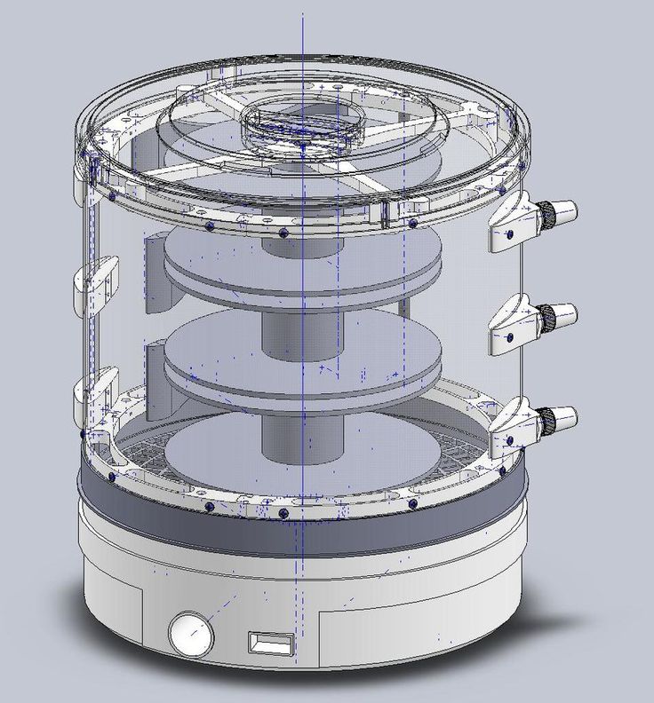 The inventor was looking for a method that would allow him to speed up the process.
One of his ideas was to apply several hundred layers of plastic and shape them using ultraviolet light. This would make for a relatively cheap and quick prototype. With this idea, he went to the leadership of the UVP. Chuck, of course, was not allowed to invent during working hours - but they were given a room and equipment.
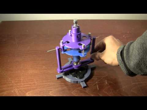
After a year of overtime, the inventor created the first prototype of an electrolytic 3D printer. He worked with a photopolymer, a substance that can change from liquid to solid under the influence of ultraviolet rays. Hull learned how to write code to program a printer to create a prototype of a particular geometric shape. The first 3D printed object was a small plastic cup.
First SLA-1 3D Printer
Get Dressed and Come to the Lab Now
The night when the discovery was made was forever imprinted in the memory of Chuck's wife, Antoinette Hull. In an interview for The Telegraph, she even gives the exact time - 20:39 on Wednesday, March 9, 1983.
“I was at home that night and had to look at my watch when the phone rang,” she said. "I was already in my pajamas and getting ready for bed, but Chuck was still working."
"Get dressed and come to the lab right now," Chuck said on the phone. She got into her car and drove to the lab, a small room that Ultra Violet Products had given Hull for research.
In it, Antoinette saw the first 3D printed object in the world. “Holding this strange detail in his hand, he said that he had done it and the world would never be the same. That night, I knew he had achieved something great.”
Chuck Hull and his wife
Chuck's company didn't have the funds to finance development. He recalls: “I received a patent for a 3D printer in 86. And so I come to the head of the company and say: “We need to find a commercial application for this. ” To which he replies, “Sure, but we can’t afford it.” I had no choice, so I decided to start my own company. This was the start of 3D Systems." The first clients of his company were General Motors and Mercedes-Benz.
The company is still operating. Chuck, now 79, does too. “My job is too interesting to quit,” he once said in an interview with CNN. In another, he gave more details: “In the late 90s, I really retired. A new manager took my place, and about three months later he called me and said, “Chuck, it's bad. Can you come back and help with some technical issues?” Since then, I've been there again, continuing to do interesting things."
3D Systems is currently focusing on programmable injection molding systems that will allow objects to be printed without first having to design molds. In addition to his work at 3D Systems, Chuck gives lectures and speaks at conferences. For example, he became one of the main speakers at last year's ASME - International Mechanical Engineering Congress.
Chuck Hull remains a very humble person. In 2014, the European Patent Office presented him with a prize for the best inventor working outside of Europe. To this he replied only: “I am pleased to receive recognition of my merits. I've worked hard and hard, and that's what I'm going to do next."
He rarely interacts with the media. Below is one of his few interviews given to Industry Week. It is from 2013, but has not been fully translated into Russian. In it, Chuck Hull told how he himself did not believe in the commercial success of his invention for a long time and about whether it could ever compete with traditional production.
You invented stereolithography in 1983. After 30 years, the market for additive manufacturing began to grow rapidly. People think that this is some kind of new phenomenon. What do you think about this boom? Did it start too late?
When we first started doing 3D printing, I never imagined that it would become so popular.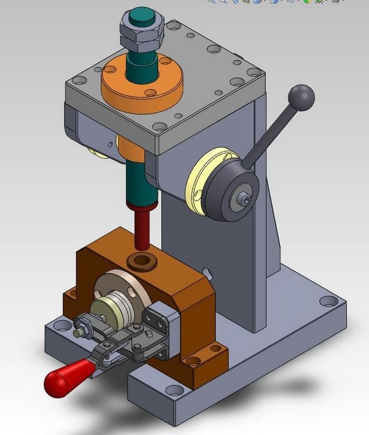
It seemed to me that this path would take 25 years, if not more. Such is the history of all inventions. It doesn't happen that you invent something like a 3D printer and a crowd of buyers immediately starts to beat on your door. It takes a long time to understand what you have invented and how it can be improved.
3D printing isn't easy. You see the finished device. You think that it is very easy to use it, but it is not. We at 3D Systems have been perfecting the first printer for 10 years. During this time, we managed to go from an idea to the implementation of a finished device in the industrial sector.
But the last few years have surprised me. It certainly came as a surprise that people recognized 3D printing as mainstream.
When did you get the idea to create 3D printing? How did you come up with the stereolithography method?
I started out as a design engineer. The development of new plastic injection moldings that we were engaged in was a very laborious and costly process.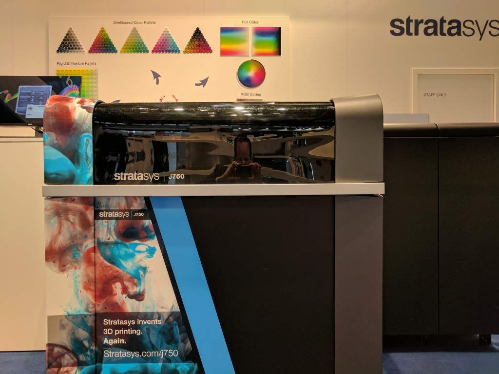 In the beginning, you designed the look of the part, made drawings, discussed everything with the toolmaker who made the mold for the plastic part. Then this form was sent to the caster, who made the spare part. The whole process took 6-8 weeks.
It took a long time to make, and the first piece that came out was never perfect. It had to be redone and the production cycle started again. Many months passed before you received a part that you can test.
Naturally, we tried to do something about it.
I decided to see if I could think of a way to get that first part faster, so that all iterations would go through quickly, and then quickly get the final version for production.
I went through a bunch of ideas that didn't work and then came up with what ended up being stereolithography. On March 9, 1983, I produced the first part with this method.
Then you applied for a patent in 1986 and co-founded 3D Systems. But who were your clients? Did any of the industries see the potential at such an early stage?
When we first launched the company, we immediately sent “scouts” to see if there was any interest from the industry. And he was. In fact, interest in prototyping has been huge, mostly from automakers.
Car companies at that time were trying to produce high quality cars. American concerns at that time were rather clumsy. They could not quickly release new models, and the quality of production lost in the global competition.
So they had a huge interest in any technology that could improve the situation. We immediately began to move in this direction, to develop technology for the automotive industry. Shortly thereafter, many manufacturers followed the same path.
Also in those years we developed methods for prototyping metal parts. Our technology was supposed to offer an alternative to traditional lost wax casting, and it was the first major offshoot of prototyping plastic parts.
We called the developed method Quick Cast. It allowed the rapid casting of metal parts from a variety of alloys and is still in use today. Mainly in the aerospace and related industries.
Now that manufacturers and consumers have realized the full value of 3D printing, what's next? Will it ever be able to compete with traditional production?
I'm not a futurist and I don't have a predictor's crystal ball - I don't know what's going to happen next.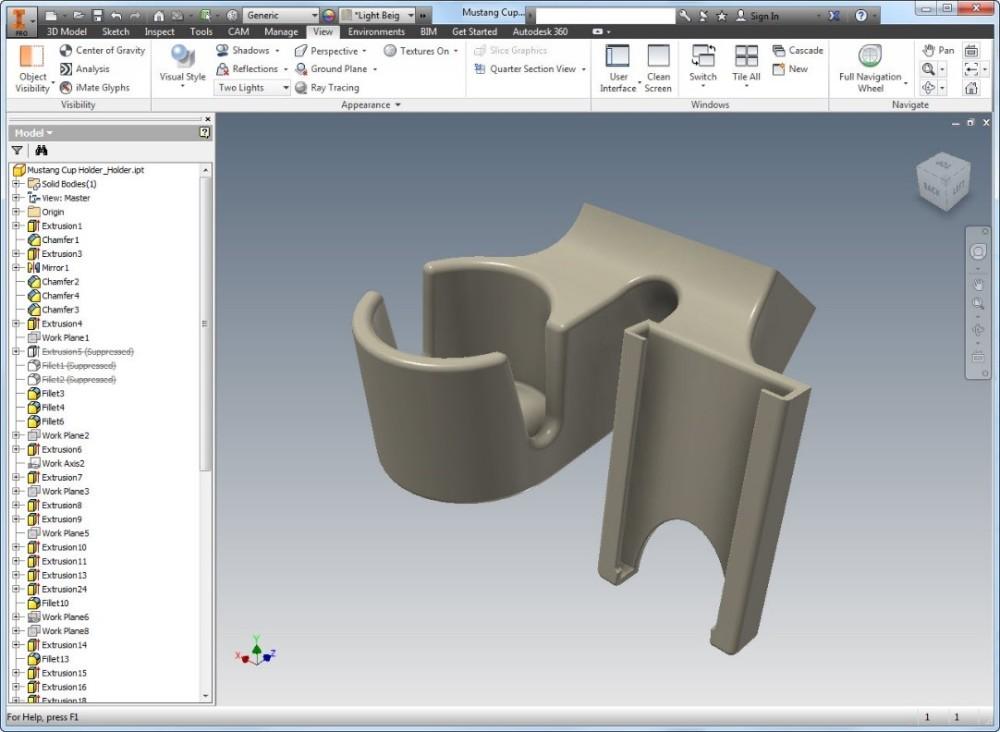 But I know that when enough smart people work on something, it always gets better.
The main advantages of additive technologies now are fine-tuning and the ability to work with complex structures. If your manufacturing process needs a lot of parts, or you need parts with many different parameters, 3D printing can come in handy.
Medical applications come naturally to 3D printing, because every body is different. When you try to do something for teeth, for example, that thing will be different for different patients. The same goes for the knees and other joints.
If you're looking into the future of 3D printing, it's probably parts with complex shapes and patterns, even at high production volumes. The speed and economic benefits of 3D printing are constantly increasing. This means that it has more and more chances to compete with traditional production.
Looking back over these 30 years, what would you say is your biggest achievement outside of the technology itself?
Back in the 1980s and 1990s, it was clear that production would gradually leave the country. This concerned not only the United States - everyone went to countries with cheap labor. I always thought it was bad. In my opinion, manufacturing should be a key capability, especially for the US. Today, the return to production in the country is associated with higher technological capabilities. I love that 3D printing and digital manufacturing make this possible.
On October 12-13, we will hold an exhibition of additive technologies and 3D scanning - 3D Print Expo in Moscow. It will be the sixth in a row.
This time we changed the format and focused on practice. There will be no conference this year - there will be an exhibition and a lecture hall. Of course, there will be workshops, a gallery of 3D printed objects and drawing with 3D pens.
Look for details and the program on the official website.
History of 3D printing
In this section, we wanted to trace the history of 3D printing from its inception to the present day, as well as give a forecast regarding the future development of technology.
The first 3d printer was invented by the American Charles Hull, he worked on the technology of stereolithography (SLA), a patent for the technology was issued in 1986. The printer was a fairly large industrial installation. The installation "grew" a three-dimensional model by applying a photopolymerizable material to a moving platform. The basis was a digital model pre-modeled on a computer (3D model). This 3d printer created three-dimensional objects, rising by 0.1-0.2 mm - the height of the layer. Despite the fact that the first device had many disadvantages, the technology has received its application. Charles Hull is also the co-founder of 3dsystems, one of the world's leading manufacturers of industrial 3D printers.
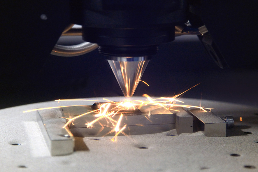
Charles Hull was not the only one to experiment with 3D printing technology, as in 1986 Carl Deckard invented Selective Laser Sintering (SLS). You can learn more about the method in another article, briefly: a laser beam sinters a powder (plastic, metal, etc. ), while the mass of the powder is heated in the working chamber to a temperature close to the melting point. The basis is also a digital model pre-modeled on a computer (3D model). After the laser passes through the horizontal layer, the chamber is lowered to the layer height (usually 0.1-0.2 mm), the powder mass is leveled with a special device and a new layer is applied.
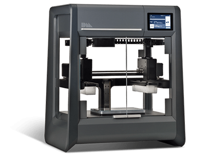
However, the most famous and widespread 3D printing method today is layer-by-layer direction (FDM). The idea of technology belongs to Scott Crump (Scott Crump), the patent dates back to 1988. You can learn more about the method in another article, in short: material (usually plastic) is fed from the heated nozzle of the print head using a stepper motor, the print head moves on linear guides along 1 or two axes, and the platform moves along 1 or 2 axes . The basis of the movement is also a 3D model. The molten plastic is laid on the platform along the established contour, after which the head or platform is moved and a new layer is applied on top of the old one. Scott Crump is one of the founders of Stratasys, which is also one of the leaders in the production of industrial 3D printers.
All the devices described above belonged to the class of industrial devices and were quite expensive, so one of the first 3d Dimension printers from Stratasys in 1991 cost from 50 to 220 thousand US dollars (depending on the model and configuration). Printers based on the technologies described above cost even more and until very recently, only a narrow circle of interested specialists knew about these devices.
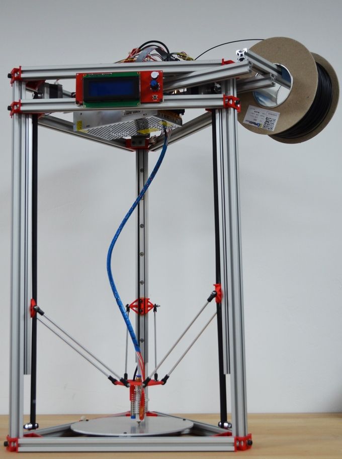
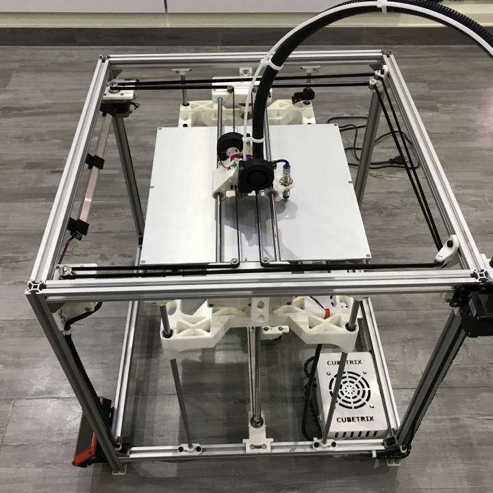
Everything began to change since 2006, when the RepRap project (from the English Replicating Rapid Prototyper - a self-replicating mechanism for rapid prototyping) was founded, with the goal of creating a self-copying device, which was a 3D printer working on technology FDM (layer by layer deposition). Only, unlike expensive industrial devices, it looked like a clumsy invention made from improvised means. Metal shafts serve as a frame, they also serve as guides for the print head. driven by simple stepper motors. The software is open source. Almost all connecting parts are printed from plastic on the 3D printer itself. This idea originated among English scientists and aimed at spreading available additive technologies so that users can download 3D models on the Internet and create the necessary products, thus minimizing the production chain.
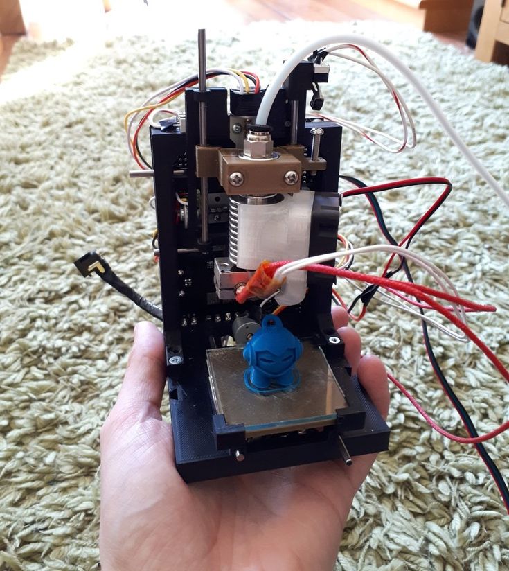
Leaving aside the ideological component, the community (which exists and develops to this day) managed to create a 3d printer accessible to the "ordinary person". So a set of unprinted parts can cost around a couple of hundred US dollars and a finished device from $500. And even though these devices looked unsightly and were significantly inferior in quality to their industrial counterparts, all this was an incredible impetus for the development of 3D printing technology.
As the RepRap project developed, 3D printers began to appear, taking as a basis the base laid down by the movement in technical and, sometimes, ideological terms (for example, commitment to the concept of open source - OpenSource). The companies that made printers tried to make them better both in terms of performance, design and user experience. The first RepRap printers cannot be called a commercial product, since it is not so easy to manage (and even more so to assemble) and it is not always possible to achieve stable work results. Nevertheless, companies tried to close the more than significant gap in quality, leaving a significant gap in cost whenever possible.
First of all, it is worth mentioning the company MakerBot, which started as a startup, took the ideas of RepRap as a basis and gradually turned them into a product of a new quality.
Their flagship product (and in our opinion the best to this day) remains the MakerBot Replicator 2 3D printer. The model was released in 2012 and later discontinued, but remains one of the most popular 3D printer models to this day " personal" segment (according to 3dhubs). The word "personal" is in brackets because this printer, which cost $2,200 at the time of release, was (and is) primarily used for business purposes, but falls into the personal segment due to its cost.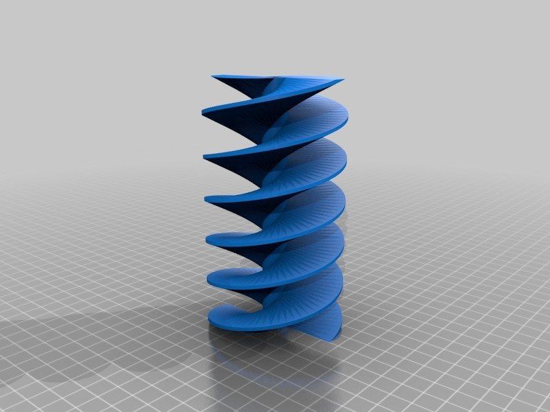 This model differs from its progenitors (RepRap), being, in fact, a finished commercial product. Manufacturers abandoned the concept of OpenSource, closing all sources and software codes.
In parallel with the release of equipment, the company actively developed the Thingiverse resource, which contains many models for 3d printing, available for download for free. During the development of the first printer and beyond, the community has helped the company a lot, testing the product and offering various upgrades. After the release of the Replicator 2 (and the closure of development), the situation has changed. You can learn more about the history of MakerBot and other companies and people associated with 3d printing by watching the film Print the legend.
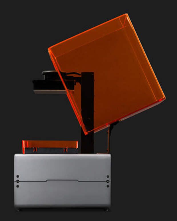
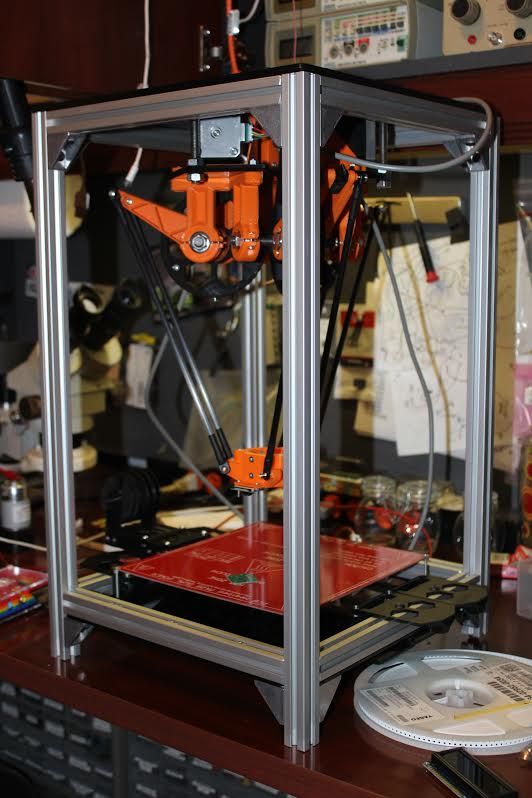
This film also highlights the history of Formlabs, one of the first companies to launch an affordable 3D printer based on SLA (Strereolithography) technology. The company raised funds for the first FORM 1 model through crowdfunding, encountered production difficulties, but eventually released an affordable and productive 3D printer, closing the quality gap described above.
Although the 3D printers described above were far from perfect, they set the stage for the development of affordable 3D printing technology that continues to this day. At the moment, the quality of FDM and SLA printers is increasing, but there is no significant price reduction, rather, on the contrary, it is growing slightly. Along with FDM and SLA, many companies are developing in the field of powder sintering (SLS), as well as metal printing. Despite the fact that such printers cannot be called affordable, their price is much lower in comparison with analogues from the professional segment. It is also worth noting the development of the line of materials, in addition to the standard ABS and PLA plastics, today many different materials are used, including nylon, carbon fiber and other durable and refractory materials.
Personal 3d printers of today are very close to professional devices, the development of which also continues unabated. In addition to the "founders" of the technology (Stratasys, 3dsystems), many small companies specializing in industrial 3D printing technologies (metal in particular) have emerged. 3D printing is also attracting the attention of large corporations, which, with varying degrees of success, are striving to take their place in a growing market. Here it is worth highlighting HP, which recently released the HP Jet Fusion 3D 4200 model, which has gained popularity among 3d printing professionals (as of 2018, it is at the top of the ranking of professional 3D printers in the quarterly reports of the 3dhubs portal).
However, 3D printing technologies are developing not only in breadth, but also in depth. One of the main disadvantages of 3D printing, compared to other production methods, is the low speed of creating models. A significant advance in terms of accelerating 3D printing was the invention of CLIP technology by CARBON, printers operating on this technology can produce models 100 times faster than classic SLA technology.
There is also a constant expansion of the range, properties and quality of materials and post-processing of products. All this accelerates the transition to the use of 3d printers in production, and not just as prototyping devices. Today, many large and not only companies and organizations are closely using a 3D printer in their production chain: from consumer goods manufacturers NIKE and PUMA to BOEING and SPACE X (the latter prints engine parts for its rockets that could not be made in any other way) .
In addition to the "classic" scope of 3D printing, today you can increasingly see news about how a house or some organ (or rather, a small part of it) was printed on a 3D printer from bio-material. And this is true, several companies around the world are testing or already partially using 3D printing in the construction of buildings and structures. This mainly concerns the contour pouring of walls (similar to the FDM method) with a special composite concrete mixture. And in Amsterdam there is a 3D printed bridge project and this list will only expand over time, since the use of 3D printing in construction can significantly reduce costs and increase the speed of work at certain stages.
With regards to medicine, here 3D printing also finds application, but at the moment it is not printing organs, but rather the use of technology in prosthetics (of various kinds) and bone replacement. Also, 3D printing technology is widely used in dentistry (SLA technology). Regarding the printing of organs, this is still far in the future, at the moment bio-3D printers are experimental facilities in the early stages, the success of which is limited to printing a few limited-viable cells.
Looking to the future, it is safe to say that 3D printing technology will expand both in breadth and depth, improving technology, speeding up processes, improving quality and improving material properties. 3D printers will increasingly replace old methods in production chains of various scales, and world production, due to this, will move towards the “on demand” scheme of work, increasing the degree of product customization. Perhaps someday, 3D printers will be widely used at the household level for the production of necessary things (the dream and goal of the RepRap movement), but this requires not only the development of technology, but also a paradigm shift in social thinking, as well as the development of a powerful design ecosystem ( 3d modeling) products (which is often forgotten).