Induction 3d printer
Metal 3D-printer based on induction heating...
Dear friends, I developed own metal additive technology and i created experimental implementation of it .This experimental implementation may call as metal 3D printer. And now i want to continue developing of it, that to create fully functional version of metal 3D printer which will able to print unique metal parts...
The ideal goal is to print parts not only from metal, but also by various composites...
Details
I started this project in 2016 when i been on first year of bachelor. More active work i stated from 2018. I developed own metal additive technology and i created experimental implementation of it. This experimental implementation may call as metal 3D printer. My own metal additive technology based on physics of induction heating and fused deposition of melted liquid metal (there is some analogy with plastic 3d printers). Welding wire is used as a consumable material (In experiments i have used aluminium alloys).
Welding wire has much more cheaper cost than an metal powder for SLS,EBM etc..
If use my technology then may give significant lower cost of all system due to my technology is not using laser modules, ovens for debinding, metal powder, etc which has relatively high cost.
I showed some photos which describes my current results of printing first lines (tracks) and dropjets from aluminium alloy. My target regime of printing - lines than dropjets. I have look that i was able to achieve lines without support between two points! - probably it is additional advantage.
Potentially, this technology allows to create printers with scalable work volume.
My metal 3D printer consist of several modules. An main module is print head. Each module i developed and created manually. I used analytical and numerical methods that to develop them. It is very complexity to find such solutions which may be optimal by all variables...
At first time, FASIE fund helped to me. But financial resources were limited within the program - to show the overall viability of the technology. Due to the lack of this resource ( btw i did more experiments than i planned) I have so far reduced the development activity on this project. And for the same reason i don't have fully functional 3d printer, but i have success to show the overall viability of the technology.
P/S 1: Dear friends, it is important for me to get helpful participation (Donate). My development activity on this project will depend on it!!! if you want to write feedback, please write in private messages.
P/S 1: Pay attention to the fact that this project while isn't open-source.
P/S 3: I understood that this description is abstract, in fact, my technology is much more complicated and takes a lot of time to describe it. By this reason description will be continued.
This project also was as my bachelor's diploma project, and i have defended it on excillent.
You can donate to the project.
-
Some module)
Sergey R. • 01/21/2021 at 20:18 • 0 commentsI decided to show this module which responsible for wire feeding. I have created this module at summer 2019. This module has high feed torque because there i utilized DC motor, has wire seeking capabilities and torque sensor. I had thoughts to use industrial servo, but i didn't use it due to budget reason and other reasons. That to control position of wire, i implemented position controller by using optical encoder (form old device), PID regulator and DC driver (which supports PWM). PID regulator i have implemented at AVR microcontroller on C++/C.
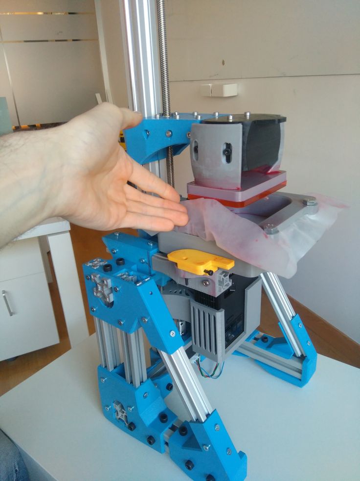 I note that PID regulators need turning of own coefficients, but i did it via additional homebrew PC software. That to use encoder i have used hardware counters and timers at the microcontroller, for better reliability. Also i programmed serial software interface that to manage this module. With torque sensor this module can provide graph of it in to any module and PC in real-time . Also i developed some special parts that to create the wire feeder.
Maybe this description abstract because this project isn't open source, thank you for understanding. If you have ideas please write in DM).
-
That to print layers....
Sergey R. • 08/14/2020 at 20:17 • 0 commentsMain problem that to give a lot print layers is microfluidic problem inside an nozzle.
 That to solve it me need try several another variants of nozzles which has another sizes and even shape, but if i change size of nozze it cause use termal isolator (from ceramic) with another sizes and custom shape. All it expencive for me (i'm student) and all i manufacture it on foreign fabrics... .
If you think that project is perspective, You can do donate.
Pay attention to the fact that this project while isn't open-source...
In the near future I will make a detailed financial estimate that to continue the project. In a rough approximation, this 5000 - 8 000$ (that to give print layers and how, therefore, the first test prints of detals ).
View all 2 project logs
Enjoy this project?
ShareHOME - 3D Inductors
3D INDUCTORS
A revolutionary solution for induction.
JOIN THE REVOLUTION
3D INDUCTORS
No brazed joints, no porosity
pure copper
Make your induction hardening
more profitable
The 3D additive manufacturing era is here, and that applies to the induction world too. GH is the first induction heating group deploying hundreds of 3D printed coils since 2014.
Our induction experience and a field-proven and patented 3D printing coil technology (3DPCoil) based on EBM makes GH 3D inductors the safest investment.
3DINDUCTORSA unique
pure copper3D printing technology
PART PRODUCTION COST & TCO comparison
3D INDUCTORS
TRADITIONAL INDUCTORS
EXTRAORDINARY
SERVICE LIFE
Total Cost of Ownership decrease
Lower Inventory
Minimized Stoppages
DESIGN
FLEXIBILITY
Continuous improvement
Complex shapes
Cooling optimization
TOTALLY
REPEATABLE
Simplified changeovers
Planned production
Identical inductors
Benefits
Progress is not an illusion.
 .. it happens.
PART PRODUCTION
COST REDUCTION
Extraordinary increase of heating cycles with the same inductor. At least double production volume.
The cost per part and the inductor stock are reduced. Total Cost of Ownership (TCO) of an induction installation is minimized.
EXTRAORDINARY
LIFESPAN
Strengths compared to current coil manufacturing methods:
- 3D printing without brazed joints and leakages.
- Improved inner cooling due to the design flexibility.
- Pure copper raw material.
STOPPAGES &
CHANGEOVERS MINIMISED
As the inductor life is much higher and the inductors are identical, the hardening machine stoppages are reduced, changeovers are simpler and the production planning is more controlled. Repairable as traditional coils.
TOTALLY
REPEATABLE
Always the same coil:
- Industrialized process. No human influence.
- From CAD design file to direct printing.

- Without porosity
CONTINUOUS
IMPROVEMENT
The original 3DPCoil design can be optimized after each changeover due to the industrialized process and coil design flexibility.
Strengthening of high intensity zones, profile adjustments, etc. are feasible.
DESIGN
FLEXIBILITY
What the traditional brazed coils do not achieve:
- Powder melting instead of tube machining
- Internal and external geometry modifications
More than printing
We accompany you in the process of incorporating 3D inductors on your production lines.
With more than half a century of experience in solutions for induction processes we can help you beyond the supply of the inductor. We can simulate, design, manufacture, test and work with you on the continuous improvement for inductors and processes.
"Impressive service life"
"We achieved a dramatic increase in inductor service life that triple the ones we had. On the other hand, the flexibility in the design to introduce improvements allowed us a continuous improvement without human factor dependency."
Jose Cipriano TejedorFormer Crankshaft Production Manager in Renault
"3DPCoil allowed us to standardise the adjustment process and to create a protocol so that any operator can adjust the inductor with guarantees. A modification of the coil was unthinkable, the former manufacturer gave us no solution"
Roberto OrtegaInductor Engineer in Renault
Previous
Next
MEETING POINTS
We would like to meet you and to find out together how you can benefit. We can either visit your company through our network or we can meet at the following events.
Previous
Next
Do you have any question?
We want to advise you personally regarding your needs
Inductive auto level sensor and glass table.
 (For example SN08-N)
 Personal diaries
Follow author
Follow
Don't want
11
Hello brothers and sisters!
My history in the world of 3D printing began not so long ago, at the beginning of the year only.
And it began with a printer called here FLSUN 3D Metal Frame Large Print Area 3D Printer , but in the common people FLSUN Cube , which, among other things, was equipped with an inductive auto-level sensor and an aluminum print table that offered a coil of double-sided Kapton.
And, as every skein of tape is supposed to, one day it ended, and I was already quite used to the auto level, and I didn’t want to refuse at all, just like changing the existing and properly working sensor to Bltach analogues.
So after the kapton ran out, a sticker (Frosted Heated bed Sticker) was bought from fuseths, by the way, these are one of the few sellers who have 300 * 300mm stickers.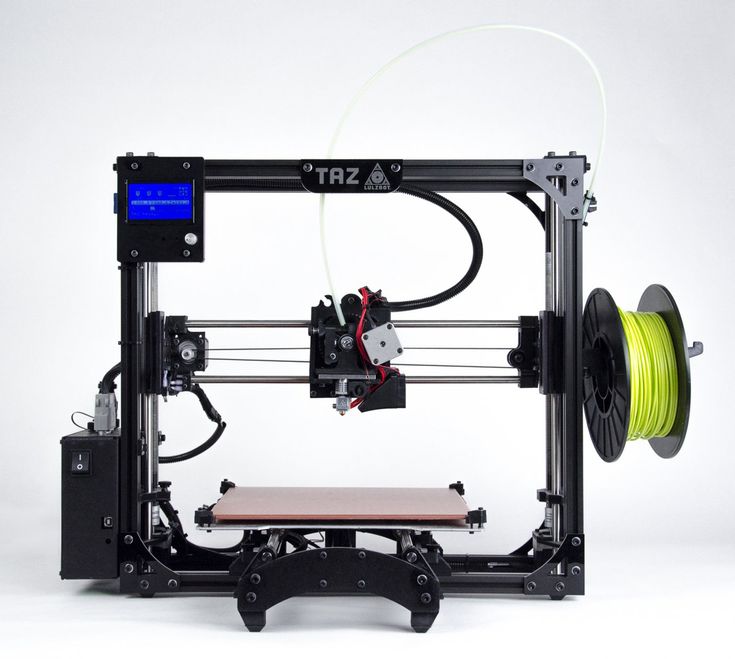 The sticker worked great, the ABS parts not only did not come off during printing, it was not a trivial task to remove something with a large contact area. And because of this, the sticker suffered quite a lot, from my hands, cuts somewhere, cracks somewhere and a few marks from the parking of the heated nozzle.
I was too lazy to bring a new sticker from China, so it was decided to take glass, or rather a mirror.
This is where my attempts to increase the range of the sensor began.
I came across an article by overseas bourgeois that, by connecting the sensor separately from 12V, the distance increases right up to as much as 6mm, which, in principle, with a mirror thickness of 3-4mm, was very good, and in principle enough.
I won't describe the experiments in this field, but in the end, due to the curvature of my hands, the case ended in complete failure, I almost burned the ISS and the BP.
With a few exceptions, during all these "adventures" I noticed that the sensor reacts to iron objects in a slightly different way than to aluminum ones.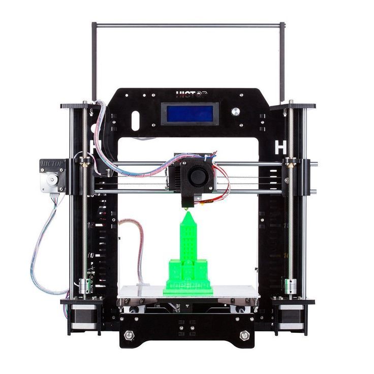
The sensor worked on an aluminum table at a distance of 3mm, while on any iron thing at a distance of about 7mm!!!
And quite by chance I had the cheapest protractor made of some kind of tin, only 0.2 mm thick, on which it was checked, and since I already knew where protractors are sold, and a couple of calls to stores selling various metals were a success was not crowned, an immediate raid was made on the nearest stationery store.
Purchased pieces of iron were placed under the auto-level points, a mirror was placed on top, and lo and behold! Everything worked great!
So, if someone has this sensor but wants to use glass, it's up to you!!!
PS. I apologize for the quality of the photo, video and text, and I also offer my sincere condolences to all the victims! Once again, thanks for your attention!
Follow author
Follow
Don't want
11
More interesting articles
cadshef
Loading
10/16/2022
417
ten
Subscribe to the author
Subscribe
Don't want
The Chinese manufacturer of a large line of FDM printers CreatBot (https://www.creatbot.com/) stubbornly...
Read more
one
Subscribe to the author
Subscribe
Don't want to
Since the problem, voiced in the 7th episode of this series, was not a quick fix, I decided not to. ..
..
Read more
103
Subscribe to the author
Subscribe
Don't want
So I had the opportunity to try to implement everything based on MMU2 (1h, 2h, 3h, 4h, 5h,). I have...
Read more
Industrial 3D printers for resin-coated sand for injection molds and polystyrene
SLS technology (Selective Laser Sintering - Selective Laser Sintering)
SLS 3D Printer Scheme for Polymer Coated Sand and Polystyrene
Technical parameters of industrial 3D printers SLS-PS
| Model | SLS-500PS | SLS-1000PS | SLS-1200PS | SLS-1400PS |
| CO2 laser, Power W | 55 | 100 | 100 | 100*2 100*4 |
| Scanning system Dynamic focus | 8 m/s | 8 m/s | 8 m/s | 8 m/s*2 8 m/s*4 |
| Print Layer Thickness | 0. 08-0.3 mm 08-0.3 mm | |||
| Print Accuracy | ±0.2mm (L≤200mm), ±0.1% (L>200mm) | |||
| Print chamber size mm | X500 Y500 Z400 | X1000 Y1000 X600 | X1200 Y1200 Z600 | X1400 Y1400 Z500 |
| Powder supply | Two pistons on both sides | |||
| Print material | Color coated sand, polystyrene | |||
| Operating system | Windows XP | |||
| Software | HUST 3DP (independent research and development) | |||
| File Format | stl, online cuts in the process of formation, changing the layer thickness, scanning. 3D visualization | |||
| 3D printer dimensions mm | X2070 Y1280 Z2080 | X2150 Y2170 Z3100 | X2350 Y2390 Z3400 | X2520 Y1790 Z2780 |
| Power supply | 3 phases, 4 lines with earth, 380V±10%, 50Hz | |||
| Working temperature | 18-25°С | |||
| Operating Humidity | Not more than 60% | |||
| Power input kW | 3 | four | 5 | 9/16 |
Catalog
Download >>> View >>>

