Cyclops 3d scanner kit
CowTech Ciclop 3D Scanner
CowTech Ciclop 3D Laser Scanner
Over $180,000 raised on Kickstarter! 1700+ scanners sold and counting.
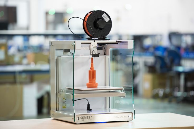
The 3D printing revolution has come, and it’s time for 3D scanning to follow. The CowTech Ciclop is a RepRap 3D scanner with a large scan volume, simple, yet elegant design, and a disruptive price point that blows any other laser scanner out of the water. The user prints the plastic parts on their own printer in any color and resolution they choose, and can assemble the scanner in less than 30 minutes. Then, simply take any object you want to replicate, set it on the 200mm laser cut acrylic turntable, and start scanning. We wanted to make sure our product was usable for anyone who owns a 3D printer, so we meticulously designed our parts for a print bed volume of only 115mm x 110mm x 65mm (4.5 x 4.3 x 2.6in) so they can be produced on even the smallest of printers.
Print your own parts and save money!
How It Works
Laser scanners are a very common type of 3D scanner that use a pair of line lasers that flash in succession in combination with a camera and a rotating turntable. As the lines flash on the object, they trace the outline of the object in red light. The camera then picks up the location of the laser lines in 3D space, converting those lines into hundreds of thousands of points, and as the turntable rotates, every side of the object is scanned into a cloud of points, which can then be stitched together to form a mesh that replicates the surface of the object with up to 0.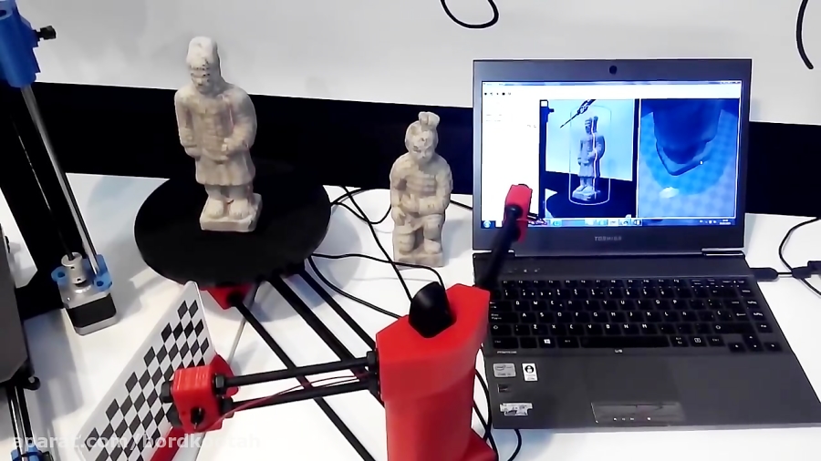 5mm precision.
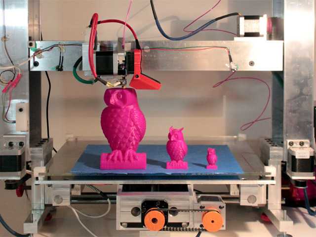
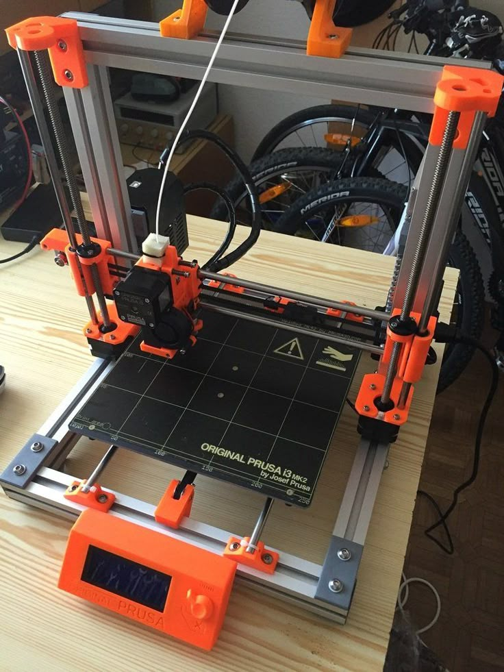
3D printed model lion, 0.2mm resolution, PLA, Prusa i3
The term 3D scanner is a bit of a misnomer. Technically, most 3D scanners are actually point cloud generators. The scanner itself is a tool to make a .PLY file, or a point cloud, made up of hundreds of thousands of points that represent the geometry of the object. The typical user will want to convert this point cloud to an .STL file, which can easily be printed on a 3D printer.
Scanned and post processed model loaded into Cura for slicing alongside the model mesh in CloudCompare
User submitted 3D prints
Once you have a digital 3D file of the part, the possibilities are endless. The CowTech Ciclop uses Horus, software developed by BQ for their version of the scanner. Unfortunately, Horus doesn't support direct .STL exports at this time, but this feature may be developed in later versions of the program. Fortunately, there are many options for post processing programs that can stitch the point clouds together into a printable file. These include Meshlab, Cloudcompare, Netfabb, Blender, and more. We recommend Meshlab and Cloudcompare, and provide detailed documentation with the scanner on how to use these programs.
The CT Ciclop scanner is a fully open source Rep Rap project, and part files and details on how to build your own can be found in the downloads section of our website.
All laser scanners can struggle with objects that are very black, very shiny, or furry, as the laser doesn't register properly with the camera. The CowTech Ciclop, is designed for experienced users who can familiarize themselves with different software programs in order to use the scanner and get high quality outputs from it.
We like to think of a 3D scanner like a video camera. A nice camera gives you the tools to take great pictures and videos, but without post production work in a video editing or photo editing program, you will likely be disappointed in the end result.
Shop Now
CT Ciclop
Ready to Scan Kit
Now Just $179
Ships Free!
Shop Now
CT Ciclop
Standard Kit
Now Just $139
Ships Free!
Shop All CowTech Ciclop Scanners and Accessories
[Review] Scanner 3D - He3D Ciclop 3D - 3D Print
Post Views: 796
The Ciclop 3D scanner has revolutionized the world of 3D scanning a little. First of all because it is completely open source, which means that the hardware and software are available to everyone. You can buy or make yourself by purchasing certain components and making the remaining 3D printing. Being a DIY kit makes it, to date, one of the cheapest scanners.
This 3D scanner is designed for anyone who likes to tinker and play with technological objects. The Ciclop purchased by me on Gearbest came after 10 days of waiting and disassembled piece by piece. It took me about an hour to mount the scaner completely. To do this I followed a video guide on the purchase page. I must say that the part of the installation was definitely the easiest. I’m going to talk about it in a little while. They recommend it for experienced users, but I am firm convinced that 3D scanning with this tool is accessible to everyone. Of course you have to be willing to tinker a bit between software, settings and adjustments.
A little bit of data about Ciclop 3DMaximum scan size: Diameter: 20 cm Height: 20 cm
Scansion time: 10 minutes at resolution (0. 45 th per displacement)
Scan accuracy: 0.5 mm
How does the Ciclop 3D scanner work?The Ciclop is a 3D scanner that works for triangulation. It has a webcam in the middle and two lasers, one on the left and one to the right of the camera. Both lasers and the camera focus on a point creating an imaginary triangle. Knowing the angles of the triangle, the distance between the lasers and the camera, the software can calculate the distance between the camera and the red point of the laser, drawing the depth.
The scaner then forms the object on the software, comparing different distances at different points of the objects, rotating them on the scanner platform. To make it faster instead of focusing on a single point, you use a vertical line, scanning many points vertically at the same time.
Cyclop the scanner you can build yourself
The original parts of the scanner can be made with a 3D printer. The manufacturers decided to put all the scanner’s print files on Thingiverse for free. Encouraging people to print the scanner and improve it by putting their own. This is part of the open source philosophy of trying to educate and engage everyone, as a community.
Unlock and build the scanner. This generally takes less than an hour. I recommend the demonstration videos you find on the Gearbest website.
Install drivers:This part can be more difficult than expected. USB drivers are not readily available and right away, without the correct ones it may seem not to work. The Logitech C 270 HD will be used for webcamdrivers. After these also those for the Arduino One, the brain of the scaner. Installs together with the Arduino IDE.
Download Horus:Horus is their free software. With Horus you can calibrate the scanner and get your scans in a point cloud format. Here’s the Horus download link.
Calibration of Ciclop 3D:
This step is very important for accurate scans. First you have to place the cardboard, the paper chessboard on the rotating platform as indicated by the wizard. Once finished then you have to select the calibration screen and start the advanced calibration of camera, laser and footer.
Configuring settings such as brightness and contrast is important for best results. There are many settings with which you can play before scanning. Optimal settings vary from scan to scan. Having good lighting is the basis for getting to have good results.
Scan with Ciclop 3D:You now place the object in the rotating platform and expect the scanning process to be complete. The scanning process typically takes about 10 minutes at maximum quality, half at medium and still half low. I do not recommend using the low resolution because a decent resolution is not reached.
Convert a file to STL:
After scanning your object, you will have a . ply file. Then you can open the .ply file with a free program like meshlab and convert it to an STL file. The reason you should turn the file into an STL format is that the 3D printer can read and print the file.
Print: Now that your scan is in STL format you are ready to print!
Factors influencing scan qualityThere are a couple of factors to take seriously before scanning that affect quality more than we imagine. The first is the light with which the platform lights up, make sure there are no shadows. Another factor may be the surface sheer of the object. If the object is shiny or reflective, it will be difficult for the camera to properly scan because the laser will be reflected on the object.
The third and last important factor is the color of the object. Red objects can cause a problem because being the same color as the laser could interfere with scanning. Mirrored objects in a very bright environment can also be a problem.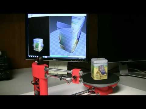 Svi found in this condition and in this case you can reduce the brightness in the settings. Finally, the dark colors do not fully reflect the red laser, so it is advisable to adjust the contrast to improve the quality of the scan.
This is a very practical scanner and one of the cheapest on the market. It’s a do-it-yourself kit. Because it’s an open source scanner, hardware and software are always improved by both the company and the hobbyists who contribute as they can. I would recommend it to those who like to tinker with technology. If you are tech savvy, this scanner can be very inspiring.
The scanner can be purchased for as little as USD 109. on Gearbest,the best market price.
If you have found this post useful, please LIKE on Easy 3D Home Facebook’s page to receive updates on all the news of the Blog! You can find other post about 3D Print in 3D Printing section!
Like this:
Like Loading. ..
..
DIY Cyclops assembly and laser scanning software
Greetings to all. Today is a small review of the Ciclop desktop scanner.
Once again, the store offered to take something for review. Since I have long been interested in the question of using this thing for the needs of decorative 3d printing, I chose a scanner.
So, the scanner itself was developed by the Spanish company BQ, which has now ceased its support (supposedly due to Chinese fakes, but it is doubtful. Now the American CowTech also sells this scanner. The source codes for 3d printing of parts of the scanner are freely available at Thingiverse (there are also links to software and electronics).0003
Links to complete documentation kits:
www.cowtechengineering.com/downloads
www.bq.com/ru/support/ciclop/support-sheet
In the kit we have such a “loose”:
The assembly is simple, however there are several points:
1. It is not worth rushing to tighten all the nuts - you still have to adjust the geometric dimensions - the convergence of lasers in the center of the site, the distance to the turntable.
2. In my stand, the camera “dangled” a little, by a fraction of a millimeter - but that was enough to skew the picture. Eliminated by laying foam material.
4. The turntable was transparent and uncoated (as in the original) - I painted it with plastidip.
5. Check the calibration checkerboard patterns. I don’t know how they printed the one from my kit - but the proportions of the squares were violated. I took it from the Internet and reprinted it myself.
6. The focus of the camera is not adjusted to the distance to the platform. He removed the cover and twisted the focus in place.
88. The economy is managed by the "native" Horus software from BQ.
After assembly, the scanner went through calibration procedures in the native Horus software.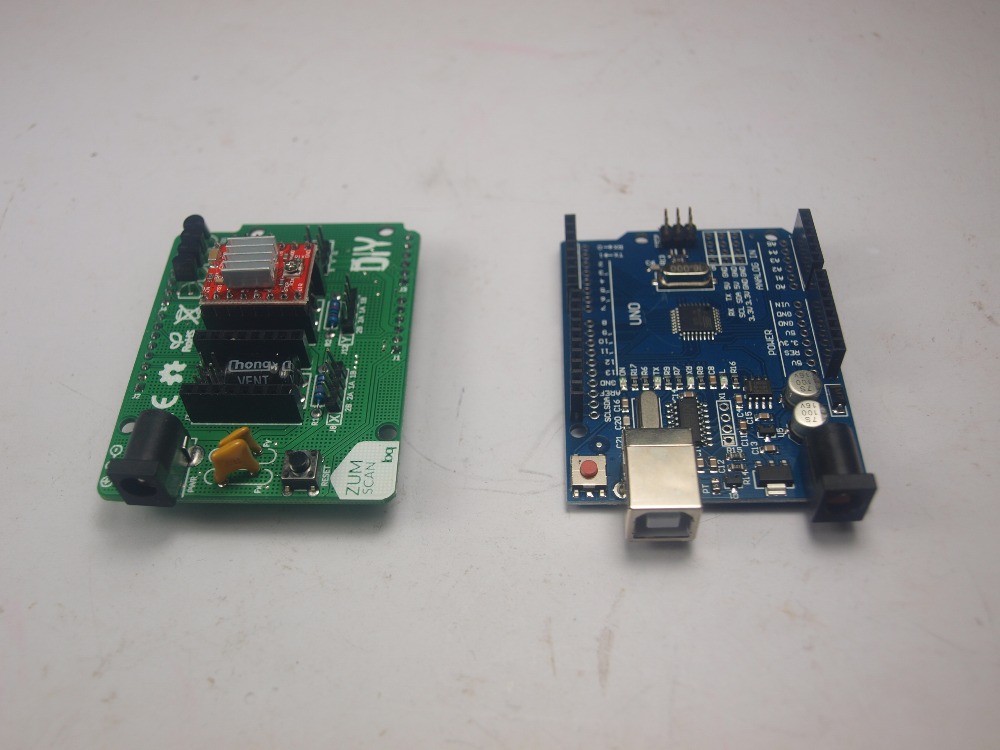
Since by this point I already knew that the quality of scanning is very much dependent on the quality of lighting (stability, diffuseness, color temperature), I took care of having a small lightbox in advance in order to at least provide more or less comparable conditions for samples.
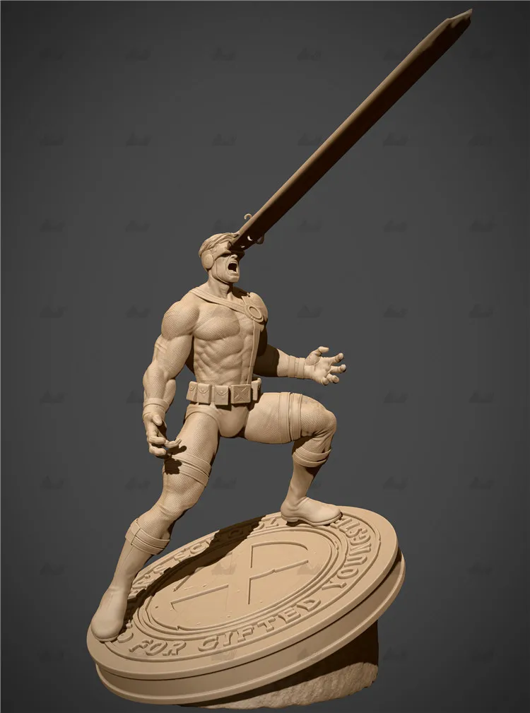
Having selected the "candidates" for the samples, I got ready.
Requirements for the object are stated as follows:
1. The object must be larger than 5x5 cm but smaller than 20x20 cm
2. The object must be opaque and still
3. The object must weigh no more than 3 kg
Difficult to scan:
1. Shiny, luminous objects
2. Too dark objects
3. Objects with a blurred surface (eg soft toys)
The result of the scan is a cloud of points in PLY format (which must then be converted to a surface). Here is a guide for post-processing the cloud and preparing the STL file.
After reading the scan optimization guide, I decided to try with a simple cylindrical object.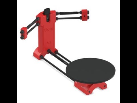
After several attempts, I was convinced that I had a common problem - mismatches in the point clouds from the right and left lasers, and the issue with proportions.
Nothing worthwhile about this except for trying to calibrate the webcam settings (they are not calibrated when the calibration wizard is running) could not be found (a dude named Jesus from BQ support has not answered questions for a long time). To do this, you need to take several shots with different positions of the calibration table. Done. The situation has improved, but not completely.
I had to manually edit the calibration file (calibration.json in the Horus-a folder) and by trial and error, scanning a cylindrical object, to achieve the coincidence of the clouds.
And everything seems to be ok:
But no - on complex objects, cloud fragments still sometimes do not coincide, moreover, many "blind" zones are formed:
impossible, at least with regular lasers.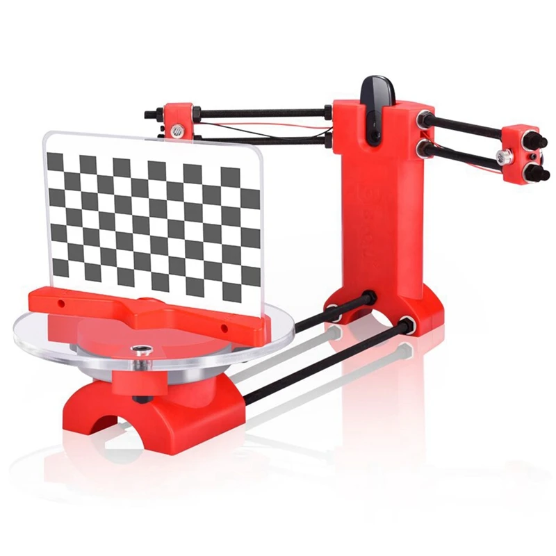
You can, of course, continue experimenting with scanning with individual lasers and trying to combine all this economy in third-party software, and then try to bring it into a viable form for STL.
All this is reminiscent of a joke about boats in bottles.
-How do you make boats in bottles?
-I put sand, silicate glue, sticks into the bottle and shake it.
It turns out all sorts of shit, and sometimes boats.
In general, I realized that I am not an adept of such creativity, and I have a suspicion that it is easier to model objects from scratch that are easier for a scanner.
And complex ones - the scanner cannot cope with complex ones in normal mode, two lasers are not enough for it - blind spots remain. To fix this problem, you need to scan in other positions and then again suffer with the combination of clouds. No thanks.
As a result - the thing will fit only for learning the basics of laser scanning, for something more - absolutely useless.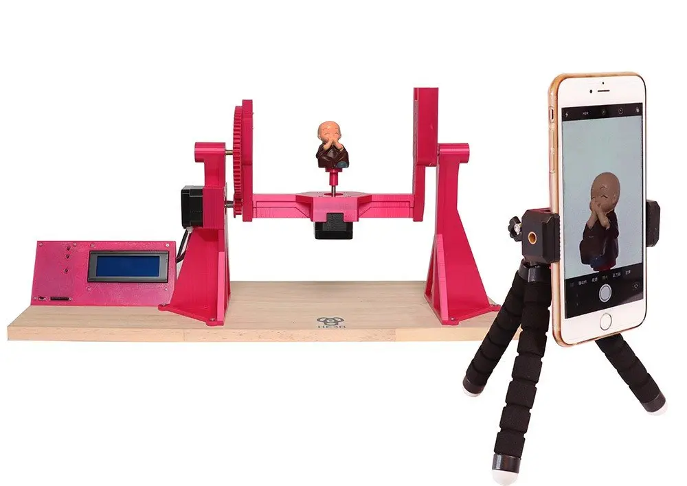 No, of course, you can get something with outlines similar to the original model, but on this (and this, taking into account all the tambourines with cloud processing), that's it. No wonder the Spaniards abandoned this case.
The store made sure - in the description it is honestly stated that the result depends on the position of the planets and the mood of Aunt Sonya from the third floor. Open source and all that, let's dance together. No thanks.
Conclusion - don't take it, but if you're into extreme hunting, assemble it yourself from the same material that your friend from the joke makes boats from.
Product for writing a review provided by the store. The review is published in accordance with clause 18 of the Site Rules.
Production and testing of laser rotational triangulation 3D scanner Cyclop text of the scientific article in the specialty "Computer and Information Sciences"
UDC 004. 89
89
Production and testing of laser rotational triangulation Ae-scanner Cyclop
9000 geosystems and technologies, 630108, Russia, Novosibirsk, st. Plakhotny, 10, postgraduate student, tel. (903) 903-54-99, e-mail: [email protected]Ruslan Vladimirovich Grishin
Siberian State University of Geosystems and Technologies, 630108, Russia, Novosibirsk, st. Plakhotny, 10, student, tel. (913)956-52-09, e-mail: [email protected]
The article presents the process of manufacturing and testing the Cyclop 3D laser scanner. The assembly scheme of the 3D scanner as a whole is given. The main parts necessary for the functioning of a 3D scanner are determined: Arduino UNO board, lasers, webcam, motor and case. A prototype 3D scanner has been assembled. An example of a cycle of operation of a 3D scanner to obtain the spatial coordinates of an object is given.
Keywords: spatiotemporal state of an object, laser, point cloud, 3D model, spatial coordinates, 3D visualization.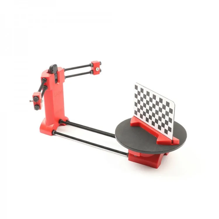
MANUFACTURE AND TESTING OF CYCLOP LASER ROTARY TRIANGULAR 3D-SCANNER
Ivan A. Knol
Siberian State University of Geosystems and Technologies, 10, Plakhotnogo St., Novosibirsk, 630108, Russia, Ph. D. Student, phone: (903)903-54-99, e-mail: [email protected]
Ruslan V. Grishin
Siberian State University of Geosystems and Technologies, 10, Plakhotnogo St., Novosibirsk, 630108, Russia, Student, phone: (913)956-52-09, e-mail: [email protected]
The article presents the process of manufacturing and testing of 3D laser scanner Cyclop. Assembly diagram of the 3D scanner as a whole. The main parts necessary for 3D scanner operation are determined: Arduino UNO, lasers, web-camera, engine, and body. Assembled a prototype 3D scanner. An example of the cycle 3D scanner to obtain the spatial coordinates of the object is shown.
Key words: space-time state of the object, laser, point cloud, 3D model, spatial coordinates, 3D visualization.
3D technologies are constantly penetrating our lives, which have their own problems. Due to the development of 3D printing and other technologies that use 3D models, there is an urgent need for a fairly high-speed and fast mode for creating them.
To meet such needs, 3D scanners were invented, which have their own methods and technologies for scanning the object of modeling.
Today there are two main methods:
1. Contact. The device probes an object through physical contact while the object is on a precision surface plate. The contact EB scanner is distinguished by ultra-precise operation.
2. Non-contact. Radiation or special light (ultrasound, x-rays) is used. In this case, the object is scanned through the reflection of the light flux.
Existing 3D scanning technologies:
1. Laser. The functioning of the devices is based on the principle of operation of laser rangefinders. Laser EB scanners are characterized by the accuracy of the resulting three-dimensional model.
2. Optical. In this case, a special laser of the second safety class is used.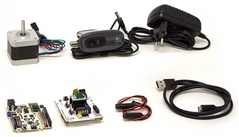 The optical EB scanner has a faster scanning speed.
The main purpose of the work is to analyze the manufacturing process of the Cyclop laser rotational triangulation EB scanner, as well as its testing and calibration to obtain the first spatial coordinates of the object, which will serve as the object of further research to obtain a point cloud, the processing of which will help to obtain a 3D model of the object. In the framework of this work, objects are understood as objects that are prototypes for creating 3D models (buildings, parts, robotic complexes, etc.). To achieve this goal, it is necessary to perform the following tasks: consider the structure of an EB scanner and the principle of operation of a laser scanner when scanning an object; create an EB model of the scanner body; assemble the case; connect electronics; configure software; calibrate the scanner.
EB scanning is a non-contact process of converting the physical form of a real object into a digital form.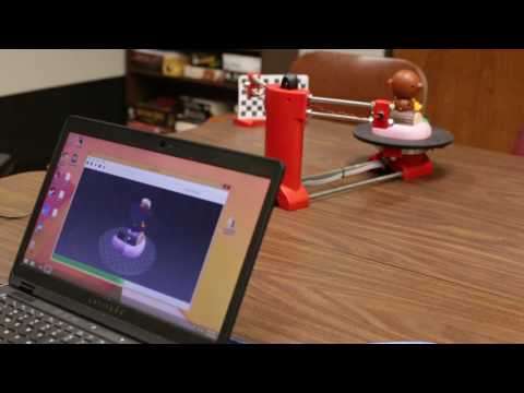 The result of the process is a three-dimensional model of the object in the form of a file, which describes information about the polygons of the object. The file is in STL format, which can be converted to such formats as OBJ, WRML, AOP, etc. Laser scanners are used in geodesy to obtain point clouds.
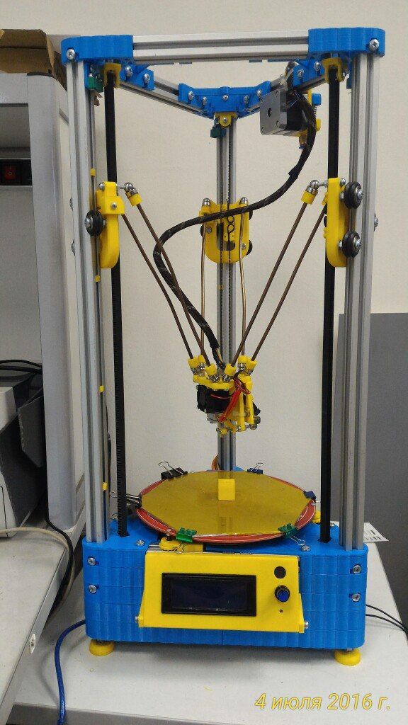
Based on the Cyclop - B1U scanner from the Spanish company bq, using the laser triangulation method, and also equipped with a rotating turntable. Case details can be either printed on any EB printer or cut using a laser machine.
Having finished the body parts in the T-flex SAB software product so that the electronic components fit the body grooves, we started the longest assembly process, namely printing the body on an EB printer.
Having completed the process of printing the housing and preparing the electronics, a new stage in the manufacture of this scanner was launched. To begin with, a fitting was made to determine whether all the details fit together or something needs to be finalized.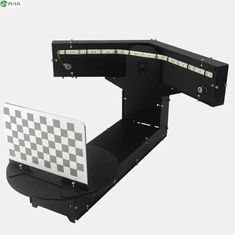 After the fitting has been made and it has been established that the parts do not have defects, you can proceed directly to the assembly of the final device.
The created scanner includes a turntable that rotates with a stepper motor connected to the stepper motor driver, leaving its connection to the Arduino UNO board. The table is connected and fixed to the scanner body with M8 studs. The case contains the Arduino UNO board, which is connected to the power supply and the Logitech C270 webcam. From the body with the help of M8 studs, mini-cases for lasers are fixed, which are also connected to the Arduino UNO board.
When the assembly process is completed, the scanner must be prepared for use. First you need to download the HEX firmware to the board, which will allow you to work correctly with the program installed on your computer. Next, install the HORUS software, also developed by bq, after installing the software for the camera to work properly, you need to install the drivers from the official website of the manufacturer.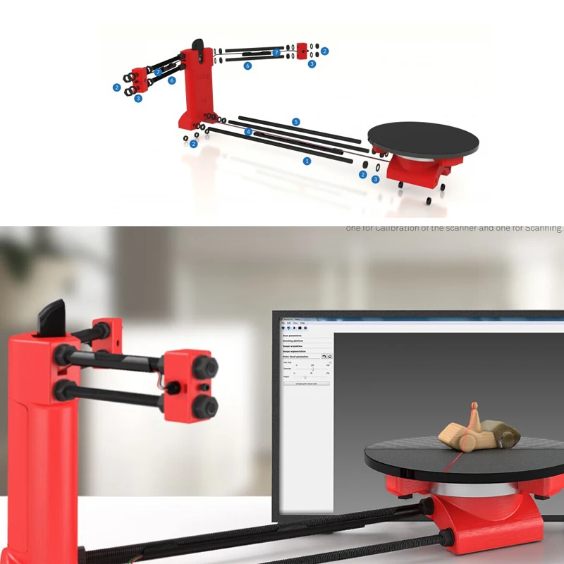 When all actions are performed, the scanner is ready to work.
The principle of operation of this EB scanner is as follows: two lasers are fixed at an angle of 30° from the web camera. The scanner's laser beams intersect at the center of the turntable. The object is placed at the intersection point of the laser beams, the laser lines are visible on the object. The webcam takes a picture of the object and receives the spatial coordinates. After receiving the coordinates, the engine rotates the table by a certain degree and the actions are repeated until the entire object is captured. As a result of these actions, a point cloud of the object is obtained, by processing which you can get its 3D model.
Before use, the first and very important parameter is the calibration of the values, which allows us to obtain more accurate spatial coordinates of the object. During calibration, a chess pattern is installed on the table, the distance from the base of the pattern to the end of its first cell is measured, in the program, after switching to the calibration mode, you need to enter the value obtained during the measurement, then the scanner will calibrate automatically after pressing the start button and will be ready to scan objects.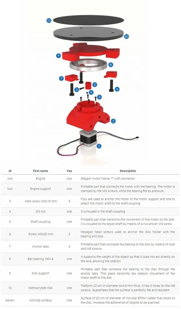
The next step is to study the results of the scan to further upgrade the scanner or completely rework it, as well as solve problems such as writing your own software for the new scanner.
EB scanners are used in very different areas of our life such as: architecture, entertainment industry, construction industry, robotics, etc.
EB-scanner is an indispensable friend who comes to your aid in the most difficult situations that arise in the process of modeling an object, since the structure of an object can be quite complex and it is not always possible to recreate an accurate model manually.
REFERENCES
1. Bolshakov VR, Bochkov AL, Sergeev AA 3D modeling in AutoCAD, KOMPAS, SolidWorks, Inventor, T-Flex: Training course (+DVD). - St. Petersburg: Peter, 2011.-336 p.: ill.
2. U. Sommer. Programming of microcontroller boards Ageshpo/Rgeeushpo. - St. Petersburg: BHV-Petersburg, 2012. - 256 p. silt - (Electronics)
3. Revich Yu. V. Entertaining electronics.