How to setup a 3d printer
How to set up your first 3D printer
For the last 10 years or so, 3D printing has been a popular buzzword. Proponents have long hyped the idea that if you think of something new or break something you own, you can just push a button on your computer and print a new one in minutes. Perhaps these ideas were overblown at one point, but after finally obtaining a printer following years of skepticism, it seems that many of the early issues with these devices have been worked out. I use mine all the time, for projects from printing a replacement part for a lamp, to crafting the body of a small rocket-launching robot.
Make your choice
If you search the web for “3D printer” you’ll find a variety of models with prices ranging from less than $200 to well over $1,000. There is, of course, some difference in quality among printers at each price level, and you’ll want to consider specifications such as resolution, the materials it can print with, print speed, and print area, which determines how big of a print you can make.
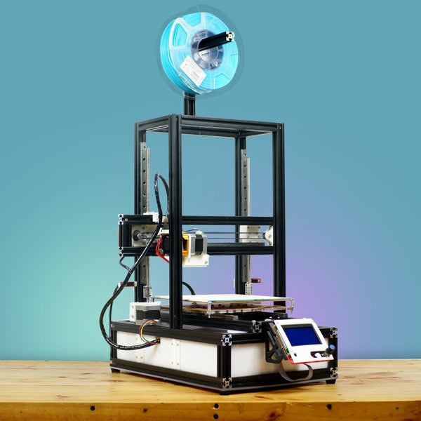
The Ender 3, which costs a little more than $200, is a popular choice for its generous 220-by-220-by-250-millimeter print area, while the Prusa i3 MK3 is a well-respected printer that’ll run you about $1,000. Personally, I purchased a Monoprice Select Mini 3D Printer V2, which is an exceptionally popular small-budget printer. It’s pretty basic, features-wise, with a relatively small 120-by-120-by-120-millimeter print area, but it cost less than $200 and worked extremely well out of the box for me.
Getting started
After unboxing your printer, you’ll need to level the bed, which simply means adjusting screws at each corner of the printing surface to ensure it’s a consistent distance from the tip of the extruder—the part that prints. More capable printers often feature an auto-leveling function, but the Monoprice Select Mini does not.
Instead, I had to move the extruder nozzle—the tip of the extruder assembly that molten filament flows out of—to positions near the four bed adjustment screws and turn them until it was 0. 05 millimeters above the bed. The manual suggests measuring this by attempting to slide a piece of paper underneath, and says that when it slides with only a slight amount of resistance, the adjustment is correct.
This method seemed a little haphazard, so I turned to a set of feeler gauges. It worked well and I didn’t have to adjust anything again for several months, but if you don’t have these gauges handy, the paper method will likely work well enough.
With bed leveling done, feed filament into your extruder. This may mean some messing about with the material until it feeds correctly, and cutting the end of the filament at an angle can assist in this endeavor. Set the extruder to the proper temperature for the material you’re using, then push filament through your extruder until you see molten plastic start to appear. Your printer may vary in its setup procedure, but after this process you’ll be ready to print.
Start printing
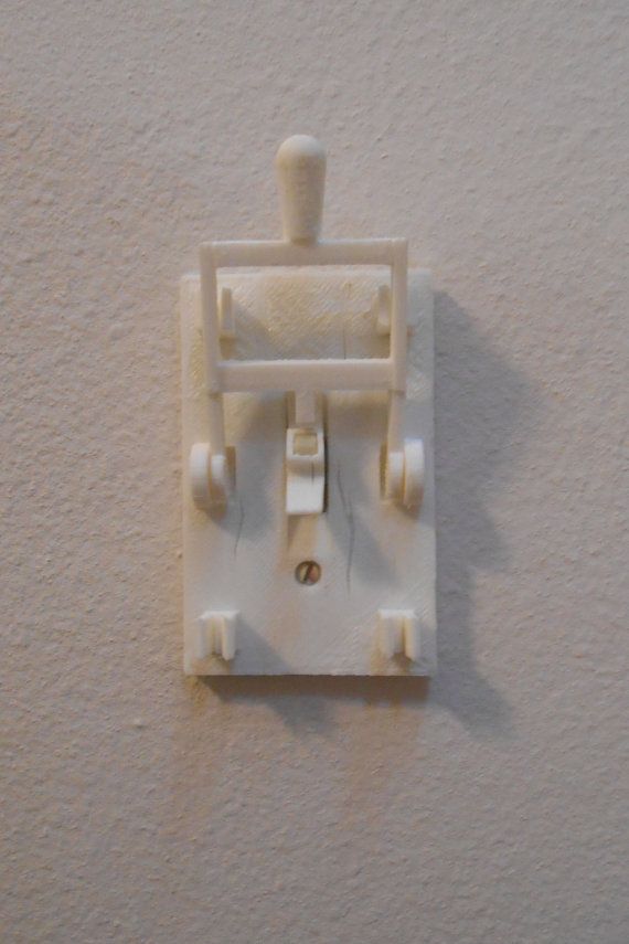
A 3D printer producing the main body of a button-dispensing machine. Jeremy S. Cook
My printer came with a sample model on the included SD card, which is a good place to start if you want to see if your printer actually works. Personally, I had no interest in a small plastic cat, and instead turned to Thingiverse to find a small enclosure for an electronics project I was working on.
These files generally come in a stereolithography (STL) format, and you’ll need to load them into a slicing program like Cura to generate the actual G-code file that controls your printer.
Obtaining files in an STL format means you can modify the models you download to fit your printer and adjust how you want things printed. For example, you may want certain wall thicknesses, print speeds, or infill properties (how solid the inside of your print will be) that affect the final product.
There are a wide variety of printable items available on Thingiverse and many other download locations, but in my opinion, the real magic of 3D printing occurs when you design custom parts.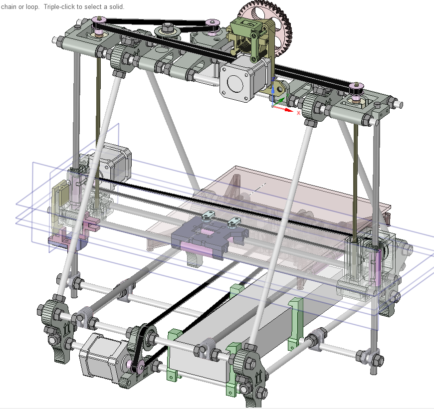 Personally, I design most of my projects in Autodesk Fusion 360, but programs such as Tinker CAD and OpenSCAD are also popular modeling options.
After making projects for years with more traditional tools, it’s amazing to be able to simply press a button and have my printer generate a part. In my case, these have usually been brackets and small spacers for robotics and other projects, but more decorative items are also quite popular and can be finished and painted to make them really stand out.
3D Printer Setup Guide | Top 3D Shop
Hi everyone! This is Top 3D Shop, and in the following article, we are going to talk about how to set up a 3D printer.
If you’ve become an owner of a 3D printer or you need to master additive technologies for work, read our recommendations on setting up a printer and creating your first models.
Getting ready
Before plugging in an assembled 3D printer, you need to make sure that the transport locks are removed. Belt buckles can damage the printer.
Depending on the model, users can apply different printing methods comprising an SD card, a USB drive, a PC with a wired connection, Wi-Fi, or Ethernet. In most cases, these are combined: many models offer 2–3 methods.
Let's compare printing from an SD card and via desktop computer or laptop.
Both methods have benefits and drawbacks. Printing via PC is "more visual"; besides, you can make changes during the process. When working with an SD card, printing is not affected by the workload of the computer; accidental disconnection of the USB cable connecting the printer to the PC is excluded. Printing from SD cards is more reliable, but sometimes printers are unable to read them. When printing over Wi-Fi, there may also occur some difficulties associated with the stability of the printer's signal reception.
The most reliable option is to pre-copy a file into the printer's internal memory, where it can be transferred by any of the above methods (usually via a wired connection or Wi-Fi, but also from an SD card or a USB drive), as, for example, in printers by Raise3D and Phrozen.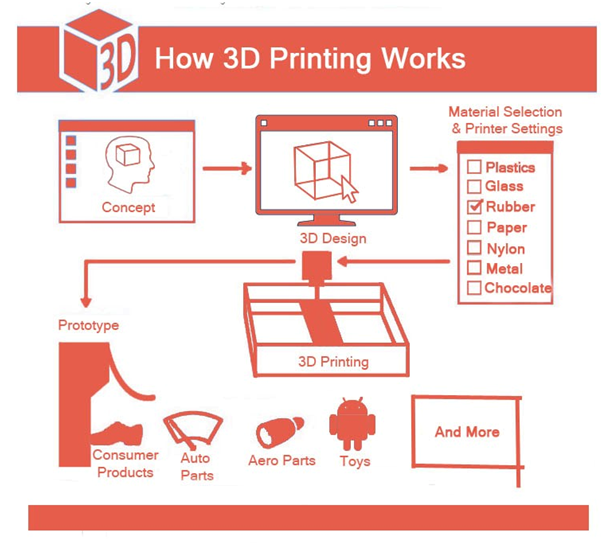
When printing from a laptop or desktop computer, the printer must be connected to them using a USB cable. Once the operating system detects the printer as a new device, it should automatically install the drivers for your printer. Otherwise, the drivers must be downloaded from the Internet or installed from the media that came with the printer.
For printing from an SD card, a card with 3D object files is placed in the corresponding slot of the printer. Typically, an SD card with several test model files is supplied with the printer.
Read more about 3D printer connectivity, possible difficulties, and their solutions.
3D printing software
Today's market is abundant with software used in 3D printing. There are many paid and free programs for 3D design, model editing, slicing. Some of them are intuitive and suitable for beginners, while others can be understood only by professionals.
To learn more, read the full guide to the most popular, proven software for modeling, processing, and printing 3D objects.
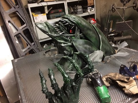
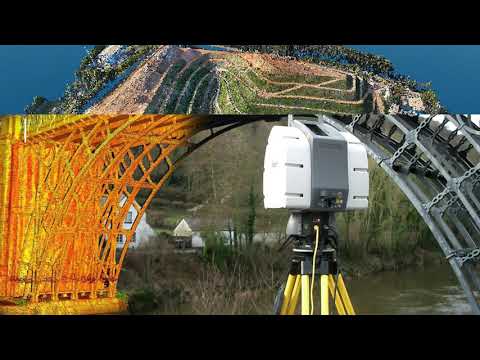
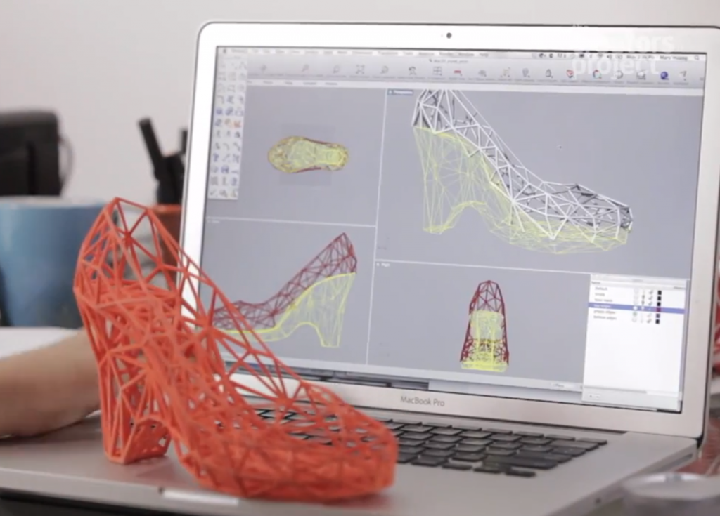
3D design and file formats
Any printing starts with finding or creating a 3D model, which can be made from scratch through 3D design or based on a 3D scan. 3D design allows you to embody an idea in a three-dimensional model. Check out the Top 3D Shop blog for an overview of free 3D modeling software. It will take at least a month to master them properly, so first, we recommend downloading models from the Internet or contacting specialists in 3D design. The most popular resources for downloading objects are thingiverse.com and grabcad.com, you can also check out our model finder.
Downloaded files may turn out to be flawed: sometimes models require error correction. The model grid must be hermetic: it is necessary to check the presence of space where it should be and the absence of holes where they should not. Also, there must be no self-intersections, “hanging” points, micron gaps; the normals should be located correctly.
Source: 3dtoday. ru
ru
Windows 10 has a pre-installed application for viewing and basic processing of 3D objects: formerly it was 3D Builder, in later versions — Paint 3D. This program is suitable for novice users.
Experienced users can employ Netfabb Studio Basic or Solid Inspector with the free Sketchup plugin, which will allow you to find errors and restore models: edit the grid, fill holes and remove double surfaces, fix polygons and divide models along orthogonal planes.
Although the model can be fixed in many slicers, it is better to use highly specialized software.
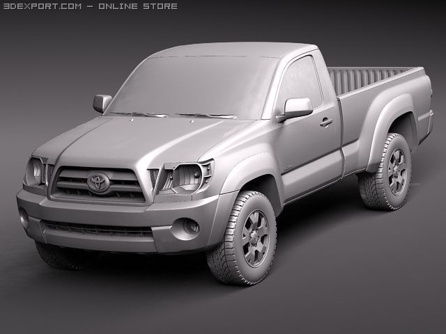
The two most used file formats in 3D printing are .STL and .OBJ. Before printing, they are converted with the help of slicers into a control G-code recognizable by printers.
Slicers are programs that split a 3D model into layers consisting of a path with or without filling. The strength and weight of a model depend on the percentage of filling. A hollow model is printed significantly faster, requires less material, and features less weight, but suffers from extremely low strength. A model with a 100% fill, on the contrary, is as strong as possible but consumes a lot more material and takes incomparably longer to print. Here it is important to maintain a balance — the optimal filling of models of different sizes and for different purposes will vary a lot.
Most often, beginners use programs that come with the printer, or universal slicing software: the free Repetier Host and Ultimaker Cura, or a paid one such as Simplify3D.
Calibrating a 3D printer
Before starting to print, the device must be calibrated. Typically, the instructions for a printer tell you how to do this.
Let's talk in more detail about the calibration of FDM printers, since they are usually chosen to get acquainted with 3D printing, due to the availability and affordable price of such devices and materials for printing on them.
Bed leveling
Source: all3dp.com
Mechanical calibration of a printer using FDM technology represents leveling the plane of the print bed, that is, the build plate.
The purpose of leveling is to position the platform so that the movement plane of the extruder XY axes is parallel to the plane of the bed surface. The calibration sequence varies depending on the model — read the instructions for details. Calibration is usually a matter of tightening four adjusting screws at the edges of the platform.
Source: all3dp.com
This calibration has one drawback — the middle of the bed remains unleveled. The problem is relevant for inexpensive printers where the plate surface is uneven. To check the center of the platform, you can print the first layer of several models located at the edges and in the center of the print bed.
When heated, the bed undergoes thermal expansion, which inevitably leads to deformation. If the first layer doesn't peel off, the problems with the uneven bed are solved by selecting the printing parameters for the first layer: low speed (15 mm/s), a slightly higher temperature, the filament feed is increased if there is a large gap and lowered if the gap is small.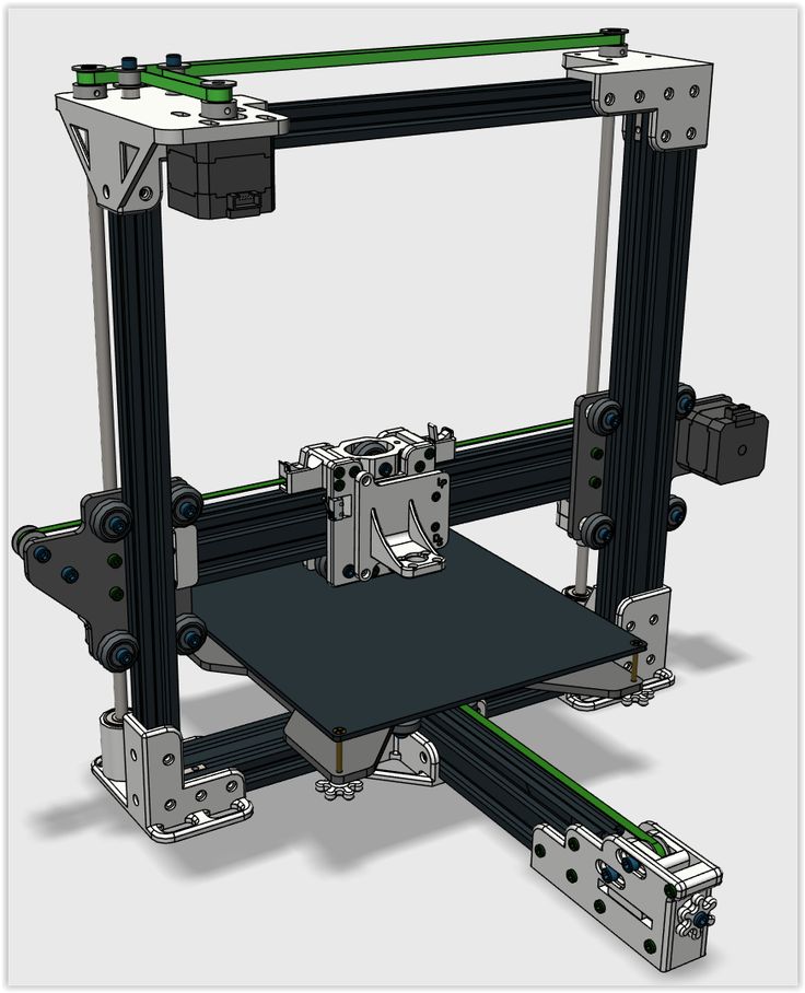
If the bed is so uneven that printing is going well in the corners but in the center, it is either too high above the bed or rests against it, then it is recommended to fix glass on the bed and print on it.
Aside from leveling, it is necessary to set a working zero point — the height of the nozzle above the bed, from which printing starts (z=0). This height is approximately equal to the layer height (thickness of a sheet of paper). But it also depends on the properties of a filament. More fluid plastics (ABS, etc.) require less height, more viscous (such as PETG) — on the contrary.
For some 3D printers, setting a working zero and bed leveling go as one procedure; for other models, these are separate actions. In the latter case, follow the instructions for a specific model.
Bed leveling should be carried out not only before the first print but also after moving the printer from place to place, as well as when there arise problems during printing, or if you had to use force when removing a print and the clamping screws may have loosened.
Auto bed leveling
The automatic leveling of the print bed is carried out using a probe or similar devices (sometimes the printhead nozzle itself serves as a probe if the design provides for an appropriate sensor). They come into contact with the bed surface at the points specified in the firmware. Thus, the printer builds a virtual plane taking into account the unevenness. Most often, this plane does not coincide with the real horizontal plane of the bed, but the calculated tolerances allow printing models with a flat base.
Settings
Once mechanical calibration has been performed, it is necessary to set the optimal parameters for the first print. They can be configured manually or with the help of a 3D printer calibration utility.
Consumables
FDM printers use a spool of plastic wire — the filament, the most popular of which are ABS and PLA.
ABS models are more durable, they are designed for use in machinery and can endure friction and environmental influences.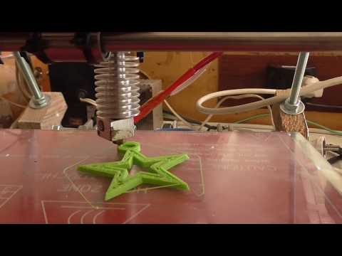 For prototyping and design objects, PLA is more suitable.
First printing
Source: all3dp.com
After the printer is warmed up and configured, you can start printing. As the first model, users often choose one of the test ones: a cube, a 3D Benchy boat, or a temperature pyramid.
For the printed model not to come off the print bed, delaminate or deform during printing, it is necessary that the first layer of the model adheres well to the bed.
To achieve good adhesion, it is recommended to print the first layer at a slower speed than subsequent ones. Thus, the plastic has time to stick to the bed surface. Besides, it is advisable to make it thicker to compensate for the unevenness of the bed or the underlay placed on it.
The following items can also be of use for good adhesion: masking or blue tape, heat-resistant tape Kapton, glue stick, hairspray, beer or cola, ABS or PLA solution in acetone, (self)-adhesive films, glass or mirror.
There are some more auxiliary methods to achieve good adhesion: rafts, brims, and skirts. A raft is a specially printed underlay that is placed under the product. Be aware, though, that the raft spoils the surface of the model. Brims are printed around the perimeter of the object without touching the base. They are easier to detach from the model than rafts. A skirt is a brim that doesn't touch the object and is at a distance from it. Skirts are primarily used to test the printer operation. A high skirt protects the model from drafts and uneven cooling.
Printing with supports
For complex geometries, slicing programs generate special supports for overhanging elements. Even though the supports spoil adjacent surfaces (if they are printed from the same material), one must understand that without supports, overhanging elements cannot be printed — they will sag, and the model will lose shape. Printing without supports is acceptable for walls with an inclination angle of no more than 70 degrees.
In printers with two or more extruders, supports can be printed from a material whose solvent does not interact with the main model material — for example, from PVA (water-soluble) or HIPS (D-limonene-soluble). This allows removing the supports as delicately as possible, without leaving marks on the surface and with no need for mechanical removal and subsequent cleaning.
Printing problems and their solutions
There are a lot of problems associated with mastering 3D printing: from assembling the device to incorrectly printed models. Here are a few points to note:
- When choosing a model to print, it is necessary to correlate its design with the dimensions of the printer. Some models can be printed in parts and glued together.
- It is crucial to take into account the operating conditions of a model. It would be unreasonable to print bakeware from materials with a melting point of 105–150 ℃ when the oven temperature is about 200 ℃, nor can you use toxic plastics for printing objects that contact food.
- Not everything has to be printed. Some things are easier to make from off-the-shelf materials than spend time modeling, printing, and post-processing.
- It is not always possible to immediately set the correct printing temperature: it may vary for materials by different manufacturers. Besides, thermistors in different printers have different sensitivity. It is for this purpose that temperature pyramids and their analogs are printed.
Conclusion
As is clear from the article, it takes some time to master 3D printing. At first, it may seem that there are too many subtleties, but they are easy to remember and impose no difficulties providing you have practiced and acquired some skill. All you need is desire and enthusiasm.
Instructions for setting up all the mechanics of a 3D printer: from belts to speeds
The quality of the printed models directly depends on the mechanics of the printer, namely on its correct settings. Any elements of the printer wear out over time, so the printer must be set up at least once every 5-6 kg of printed filament. With the help of the short instructions described in this guide, you can quickly and easily set up the mechanics of your printer: belt tension, motor current, motor steps, acceleration, jerk and speed.
Mechanics includes
3D printers of any design always contain the same things: Axes and rails along which the elements of the printer move and motors with belts that set these elements in motion. In a classic printer design, there are at least 3 motors (one for each axis), 3 rails (one for each axis) and an electronics board that controls the motors. The latter can hardly be called part of the mechanics, but since it controls the engines, it also indirectly affects the quality of the model.
Printing defects due to mechanical problems
Before changing anything in the printer, you need to decide what exactly needs to be configured.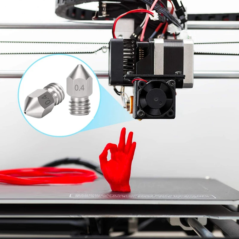 Often defects are visible visually. Our blog has an article about most printing defects, which details the reasons for their occurrence. The following is a list of defects and what element of mechanics they are associated with:
-
Layer shifting - Belts, Motor current, Guides
-
Ringing - Guides, Speed
-
Incorrect model geometry - Guides, Motor steps, belts
As you can see, all the above problems do not interfere with the printing process itself, but the result leaves much to be desired. Sometimes mechanical errors can completely stop the printer from working. Therefore, it is better not to take the situation to extremes and, if any problems arise, immediately start checking and configuring the 3D printer.
How to save settings
To fix some defects, you need to change the printer software settings. Therefore, before adjusting the mechanics, it is necessary to understand how to properly store the settings inside the printer.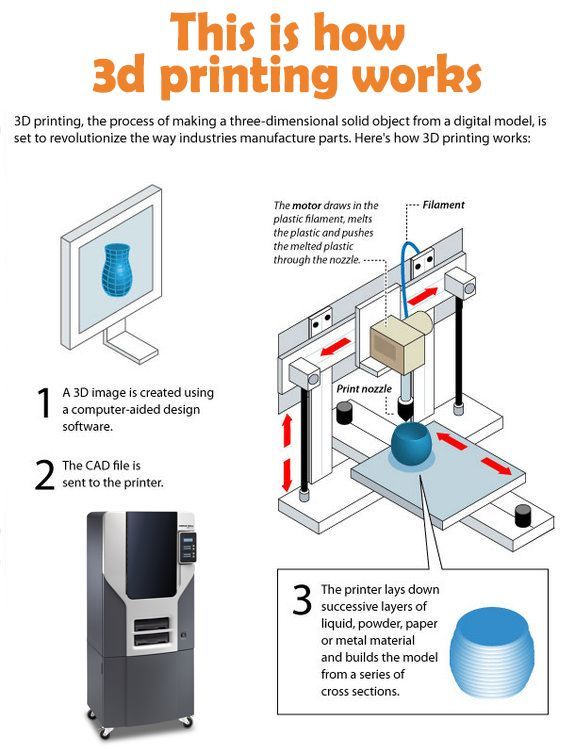 There are 3 ways to do this:
All settings are located in the corresponding menu of the printer
Depending on your firmware, this manual will indicate code sections for MARLIN firmware in the configuration.h file
We first enter the parameters into the printer and then store them in EEPROM - the internal memory of the microcontroller. Or paste all the necessary settings at the beginning of GCODE. To learn how to do this, read our article on working with GCODE and creating macros.
To save to EEPROM, you need to send the printer a command to change some value (which can also be inserted into the initial GCODE), and then send the M500 command (save the current settings to permanent memory). The EEPROM function must be enabled in the firmware, for this you need to remove two slashes in the line:
//#define EEPROM_SETTINGS
Whichever option you choose, you should be careful when using any commands. You will not be able to harm the printer in any way when changing the settings, but if you make a mistake, you will have to look for the cause of possible further problems for a long time.
Setup instructions
Now you can start setting up the printer itself. If you decide to set several parameters at once, then it is better to use the order of adjustments as in the article, since some of the settings are related to each other and if you use the wrong order, adjusting one element of the mechanics will override the settings of another element. For example, you should not adjust the motor steps before tightening the belts, as changing the length of the belts will change the "true" steps per millimeter of the motors. Also, before setting up, you must make sure that there are no backlashes in the printer frame, tighten all belts.
Belts
The first thing to start setting up the printer is the belts. They directly affect the geometry of the model and, when pulled too much, they cause a lot of problems: displacement of layers, changes in geometry, ripples. First you need to make sure the belt is intact. To do this, look at the entire belt, especially the areas where the belts bend. If the belt has outlived its usefulness, then you can see a section of the belt where the distance between the teeth has greatly increased and a metal wire (cord) is visible between them. This means that it's time to completely change the belt.
Broken belt with broken cords
If the belt is intact or you have already replaced it, then you can proceed to the next step. Depending on the design of your printer, you need to move the roller through which the belt passes. The tension should be such that the carriage or table moves effortlessly, but at the same time, when moving quickly, the belt should not slip the teeth on the motor gear. Adjust the tension of the belts on each axis of the printer using this method.
Tip: if your printer came with a belt tensioner in the form of a spring attached to the belt itself, remove it. Due to the flexibility of this tensioner, printing defects will occur, such as protruding corners on the model.
It is better to adjust the belt without using this tensioner.
Belt tensioner
Current motors
As we know from the school physics course, the power of the engine depends on the voltage and current strength. Since the voltage on all printer electronics is the same everywhere, the only thing that can be changed is the current on the motor. More precisely, it should be said the maximum current that the driver will supply to the motors. To change this limit, you need to climb inside the case and find the printer board. On it you will see the printer driver. We are interested in a small potentiometer on the driver itself (in the picture below it is indicated as a tuning resistor).
Potentiometer location example on driver
For adjustment, you will need a voltmeter and a small Phillips or flathead screwdriver. Before proceeding further, it is necessary to calculate the maximum current supplied to the motors. Different formulas are used for different drivers, the most popular ones will be listed in the table below:
| Driver name | Formula | Explanations |
| A4988 | Vref = Imax * 1.25 for R100 | To understand which formula to use, you need to find a resistor with the signature R100 or R050 on the driver. They are located next to the driver chip. |
| DRV8825 | Vref = Imax / 2 | |
| LV8729 | Vref = Imax / 2 | |
| TMC2208 TMC2100 TMC2130 | Vref = Imax * 1.41 | One formula for all drivers |
The value of the maximum current (Imax) depends on the motor controlled by the driver.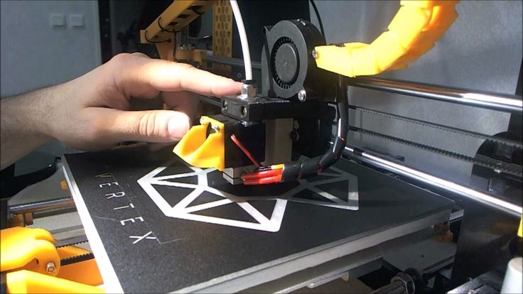 This can be found in the engine specification or on the sticker on it. The following are the currents for the most popular motor models:
17HS4401 - current 1.7 A
17HS8401 - current 1.8 A
17HS4402 - current 1.3 A
Substituting the value into the formula, we get the Vref value for the maximum current supplied to the motor. But at this value, the engine will get very hot, so the resulting Vref value must be multiplied by 0.7. For example, for a motor with a maximum current of 1.5 A and a TMC 2208 driver:
Vref=1.5*1.41*0.7=1.48V
Now the resulting value can be used when configuring on the printer itself. To do this, disconnect the wires going to the motors, turn on the printer and place one voltmeter probe in the center of the trimmer, and the second probe to the negative terminal on the power supply (you can also use the negative terminal on the printer board and the contact on the driver, labeled as GND). You will see some value on the voltmeter screen.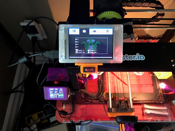 Turn the trimmer clockwise to decrease the Vref value and counterclockwise to increase it.
Attention: you should not specify a Vref value higher than the maximum calculated for your engine! Otherwise, the engine will soon break down!
Once you have adjusted the value on the drivers, you can turn off the power to the printer, connect the motor wires, and put the case back together. This completes the driver setup.
Motor steps
When setting up motor steps, you will need a ruler. For convenience, you can use the program Repetier-Host. The adjustment for each of the three axes occurs according to the same algorithm:
-
Set the caret to zero coordinates (Autohome or G28)
-
Move the carriage some distance
-
We measure how far the carriage has traveled
-
We calculate the correct number of steps per millimeter using the formula:
True steps per millimeter = current steps per millimeter * reported distance / distance traveled
For example, if the printer was set to 100 steps/mm, we tell the printer to move 80mm and the printer travels 87.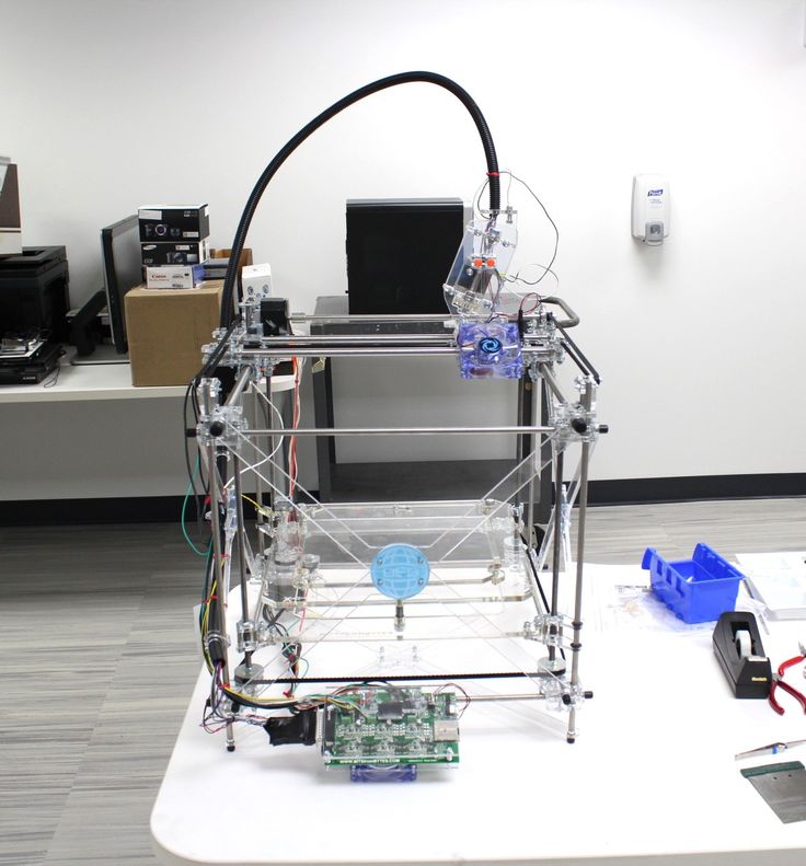 5mm. Then the correct steps per millimeter would be 100 * 80 / 87.5 = 91.42 steps/mm. For the convenience of measurements, you can fix a ruler on the table, and a thin object, such as a needle or pin, on the carriage. Then it will be possible to accurately measure the distance traveled. The extruder uses a partially different algorithm to measure distance:
-
Inserting plastic into the extruder
-
Cut it right at the outlet
-
We give the printer a command to stretch the plastic a certain distance (at least 100 millimeters)
-
Cutting plastic again
-
We measure the length of the resulting piece of plastic
-
We use the formula from the previous algorithm
Next, the settings data must be inserted into the firmware in the line:
#define DEFAULT_AXIS_STEPS_PER_UNIT {X,Y,Z,E0}
X,Y,Z and E0 should be replaced by the steps per millimeter for each of the axes, respectively.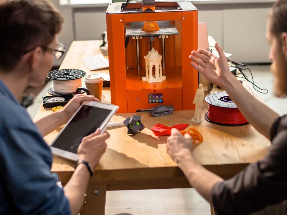 Otherwise, you need to insert this line into the initial GCODE:
M92 Ennn Xnnn Ynnn Znnn
Instead of nnn in each of the parameters, you must substitute the steps per millimeter for each axis. If you want to adjust the steps only for not all axes, then you can remove unnecessary parameters.
Acceleration
This parameter is responsible for the rate of change of speed. That is, how fast the printer will change its speed. This affects the nature of the movement of the hot end relative to the table. If the acceleration is too small, then the printer will print slowly, if it is too large, then the outer surface of the model will have visual defects: fading waves will be visible near each of the corners, as in the picture below.
To set up acceleration, you need to follow simple steps:
-
Cut a model of a standard test cube with a wall thickness equal to one nozzle diameter, without filling and top layers, bottom 2-3 layers;
-
Open GCODE file in notepad;
-
Find the G28 command at the very beginning and insert the line data after it:
M201 X5000 Y5000
M204 P500 T500
-
Save the changes, print the model according to the received GCODE and note at what parameters P and T it was printed;
-
Open the same GCODE file and change the P and T values on the second line, adding 500 to each;
-
Repeat steps 4-5 at least 3 times;
As a result, you will get several test cubes, some of which will show waves at the corners. Choose the cube that is printed with the highest P and T parameters, but that no waves can be seen on it. The number in parameter P will be the desired acceleration value. To save this value, you need to find 2 lines in the firmware:
#define DEFAULT_MAX_ACCELERATION {X,Y,Z,E0}
#define DEFAULT_ACCELERATION {nnn}
Instead of X and Y, you should put an acceleration twice as high as found earlier. And instead of nnn, you need to put the acceleration value found earlier. Otherwise, you need to insert a line in the initial GCODE:
M204 Pnnn Tnnn
In the parameters P and T, you need to put the value of the found acceleration. After that, the acceleration setting can be considered complete.
Jerk
A jerk indicates the speed with which to start accelerating. It affects the model in a similar way as acceleration: it creates ripples around the corners of the model. But it also increases the protrusion of the corners if the jerk is too small. The jerk setting is also similar to the acceleration setting:
-
Cut a model of a standard test cube with a wall thickness equal to one nozzle diameter, without filling and top layers, bottom 2-3 layers.
-
Open GCODE file in notepad
-
Find the G28 command at the very beginning and insert the line data after it:
M205 X5 Y5
-
Save the changes, print the model according to the received GCODE and note at what X and Y parameters it was printed
-
Open the same GCODE file and change the X and Y values on the second line, adding 2 to each
-
Repeat steps 4-5 at least 3 times
As a result, you will get several cubes. Find a non-rippled cube printed at the highest X and Y settings. This will be the jerk value for your printer. To save them, you need to find the line in the firmware:
#define DEFAULT_XJERKnnn
#define DEFAULT_YJERKnnn
It is necessary to substitute the jerk values for the X and Y axes, respectively.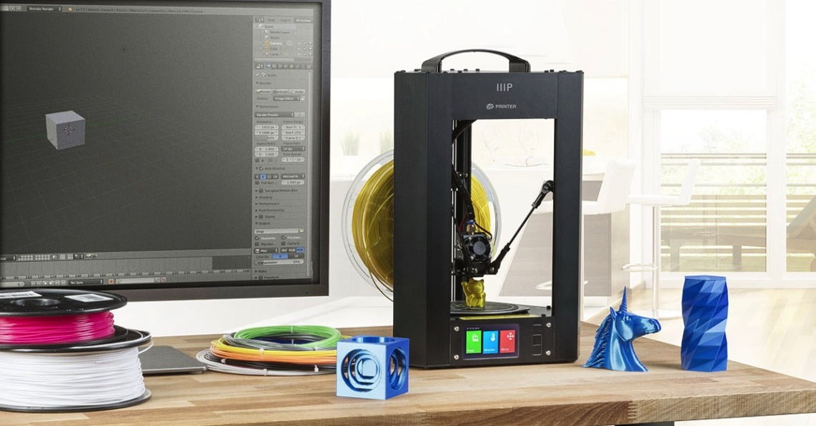 Otherwise, you need to substitute the command in the starting GCODE:
M205
Instead of nnn, you need to substitute the jerk value found earlier. This completes the jerk setting.
Speed
In fact, there are many different speed parameters, the values \u200b\u200bof which vary greatly. Let's take a look at the main ones:
This parameter is responsible for moving the nozzle without extruding plastic. The value is in the range from 80 to 120 mm/s. Limited only by the maximum speed at which the motors can rotate. Does not affect the model
This speed is important because it indirectly affects the adhesion of the model to the table. Usually lies between 15 and 30 mm/s
-Print speed of inner walls
Usually set to about 60 mm/s, it only affects the strength of the model. Depends on the maximum amount of plastic that the extruder can push through the nozzle
-Speed of printing outer walls
Usually about half the printing speed of the inner walls (30 mm / s).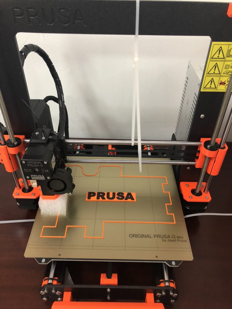 It affects not only the strength of the model, but also the appearance: the lower this speed, the smoother the walls will be.
The standard value is 80 mm/s, it only affects the strength of the model
Usually set from 20 to 40 mm/s, the quality of the upper layer of the model depends on it: the lower the value, the smoother the cover.
All of the above parameters are selected experimentally. Usually there is a simple rule: higher speed - lower quality. Therefore, do not try to find the ideal value for all situations. It is better to find values for fast printing, quality printing, and an average that will be used for most models.
Check settings
The last step in setting any of the above parameters will be to check the result. If you have written parameters in firmware or saved them in EEPROM, you can use the M503 command. It will display all printer settings on the computer. To test the settings in practice, you can print several test models:
Classic Benchy
Simple calibration cube
Calibration cat
On each of the above models, defects will be clearly visible, if they still remain after the mechanics are adjusted.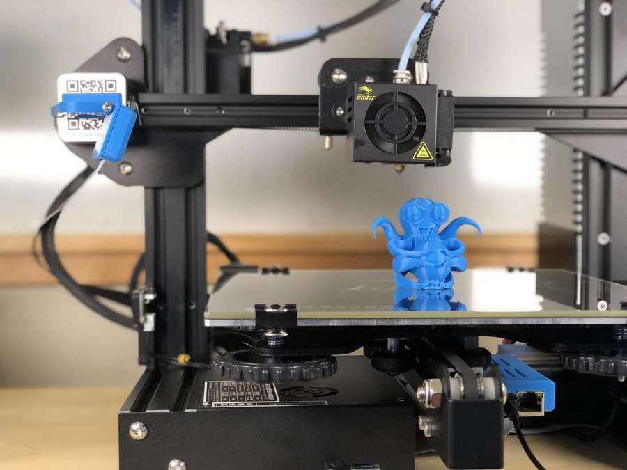
3D printer problems and settings, how to improve the quality of 3D printing
Problems and settings of a 3D printer, how to improve the quality of 3D printingAll reviews Lessons Interesting Wiki 3D Models Problems Reviews Video
12/09/2021
Lessons
Direct Feed vs. Bowden Bowden: What's the Difference and Which is Better?
Direct and Bowden extruder: what is the difference and which is better?...
10/28/2021
Lessons
The price of plastic for a 3D printer why are they expensive? It's just plastic!
To maintain constant, stable and better quality, an industrial...
10/28/2021
Tutorials
Practical guide for printing gears on a 3D printer
This material is a general guide for designing and printing on...
10/28/2021
Lessons
Meshmixer - tutorials, lessons, video instructions
If you haven't used Meshmixer before, you might also be interested...
10/28/2021
Lessons
Raft "Rafts", Brim "fields" and Skirt "skirts" - why they are needed and how to use them in 3D printing
Raft "Rafts", Brim "fields" and Skirt "skirts" » – In the community...
10/28/2021
Lessons
How to unravel a spool of filament if it gets tangled or knots
A terribly tangled spool of filament can completely stop any printing process. ..
..
10/28/2021
Tutorials
How to dry PLA, ABS and Nylon filament if the plastic has absorbed moisture, here's how to save a wet spool
Moisture from the air can easily destroy your 3D printing filament,...
10/28/2021
Lessons
PETG vs PLA: What's the difference? We explain on the fingers
PETG, and PLA are plastics of the polyester group. Like...
10/28/2021
Tutorials
5 Easy Tips for PETG 3D Printing and 3D Printer Settings
How to succeed in PETG 3D printing? Here are our five simple tips...
10/28/2021
Lessons
Carbon Fiber for 3D Printer
Recently, a number of 3D printing material manufacturers announced that...
1 2 3 … 6
Request a call back
Telephone
By clicking on the button, you agree to the privacy policy
Item added to cart
Go to cart
Product added to comparison
Compare products
Cannot compare more than 4 products
Request CP
Organization name:
Your e-mail
Your phone
Name of contact person:
Legal address:
Comment:
By clicking on the button, you agree to the privacy policy of
Goods on the way, find out when the delivery is
Your name:
Your e-mail
Your phone
By clicking on the button, you agree to the privacy policy of
Contact us
How to call
By phone +7(495)155-45-19.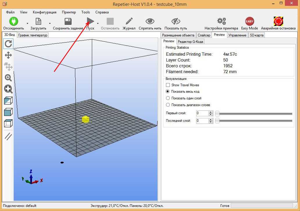 Your call will be answered by an answering machine. We won't call back if you don't speak up. Each request is processed, we contact clients in accordance with requests. Prepare the information you want to report, send it to the answering machine and we will call you back. We kindly request: do not be silent and do not hang up, this is just an answering machine. 🙂 Other most effective ways to get in touch:
- Write to Telegam @techno3dru
- Write to Whatsapp +74951554519
- Write Email [email protected]
Is the product in stock
On the product page, under the product name, there are 3 statuses:
- In Stock - We have this item in stock. Make a purchase with the Buy button.
- Pre-order - goods on the way, delivery soon. Find out about delivery times by clicking on 'Delivery times' or make a purchase using the Buy button.