How does a 3d printer work with metal
How does Metal 3D printing work?
Data courtesy of GKN Metallurgy
Metal Additive Manufacturing — a world of possibilities
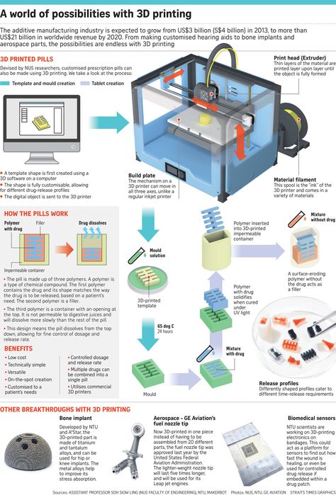
Metal Additive Manufacturing (MAM) is a disruptive manufacturing technology that offers a whole world of possibilities. This is as true in terms of offering new levels of design freedom, as it is about the sheer choice of metal materials that can be used with metal 3D printers.
Take titanium as an example. Where conventional processes can be costly, Metal Additive Manufacturing can be an attractive technology for the processing of this advanced material, and others like it, such as alloys which can only be manufactured under high cooling rates.
Metal Additive Manufacturing opens a world of new applications and opportunities — one great example is in the transportation sector, where it can enable lightweight engineering and design techniques, which are becoming more important in efforts not only to reduce, but also to redistribute a vehicle’s mass, in order to save energy during use, reduce manufacturing costs or improve the working performance.
Metal Additive Manufacturing also allows for the cost-effective production of customized products in the medical and orthodontic sectors, that are personalized and “tuned” to a patient’s individual needs — and this level of flexibility also points to the potential for use within the consumer goods market.
Back to menu
Will Metal Additive Manufacturing become a mainstream manufacturing technology?
Metal Additive Manufacturing is being adopted by companies focused on innovation and creating new value. However, there are still some challenges that must be overcome — including education around applications, Design for Additive Manufacturing (DfAM), industry standards, regulations, certifications and metal materials quality — to accelerate its widespread adoption.
Back to menu
How does metal 3D printing work? Some MAM technology basics
An important starting point is understanding the main Metal Additive Manufacturing technologies and processes and how they work, in order to define which is most suitable for a specific application.
The choice of the right process and machine for your application wholly depends on various factors, including specifications, budget, and product lifecycle.
Back to menu
The most common Metal Additive Manufacturing processes
- Powder Bed or Powder Bed Fusion process
- Binder Jetting
- Direct Metal Deposition (DMD) or Direct Energy Deposition (DED)
- Metal Extrusion or Material Extrusion
Back to menu
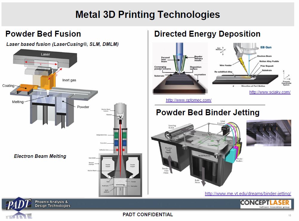
Powder Bed Fusion process
One of the most common metal 3D printing methods is the Powder Bed or Powder Bed Fusion process.
The various types of Powder Bed Fusion typically use heat or light energy, in the form of a laser or electron beam, to fuse or melt metal powder material together - and involve spreading the material over previous layers. There are different mechanisms to spread the material layer, such as a roller or blade, while a hopper or a reservoir positioned below the bed will add a fresh material supply. Once the powder layer has been distributed, the fusing or melting process is then repeated slice by slice, layer by layer, until all of the layers are fused or melted together. The 3D printed part is then removed from the powder bed and processed to create the final piece.
As the name suggests, Powder Bed processes use metal materials in powder format, and for metal additive manufacturing, these include metals such as stainless steel, titanium, aluminium, cobalt chrome and copper, to name a few.
There are different types of Powder Bed Fusion, each of which use a slightly different process to form the 3D printed part—the most common techniques include:
- Direct Metal Laser Sintering (DMLS) or Selective Laser Melting (SLM)
- Electron Beam Melting (EBM)
Back to menu
Direct Metal Laser Sintering (DMLS) or Selective Laser Melting (SLM)
Direct Metal Laser Sintering (DMLS) — also known as Selective Laser Melting (SLM), uses a laser beam to partially melt (in the case of DMLS) or fully melt (in the case of SLM) metal powder and form the material into a solid part. The solid mass is formed by heating and applying pressure to the metal material. Layers are added with a roller before a platform lowers the model to the next layer.
These processes are performed in a closed inert environment that is often pressurized to eliminate the possibility of oxygen contamination. The inert gas might change based on what will react with the material being processed, while the build plate can be heated to minimize cooling rates.
DMLS and SLM both require support structures that are usually created using the same material as the main part being 3D printed — this needs to be factored into the total cost of material required to produce the part.
Back to menu
Electron Beam Melting (EBM)
Unlike other methods, Electron Beam Melting (EBM) requires a vacuum build chamber or environment in order to fuse metals and alloys to create a variety of functional metal parts. As the name suggests, it uses a high-energy electron beam, and can only be used with conductive materials. EBM involves a number of process parameters, meaning it typically requires more expertise and time to perform to an optimal level. EBM also requires support structures.
Click image to enlarge
Click image to enlarge
Back to menu
Binder Jetting
With Binder Jetting, an adhesive liquid binding agent is dispensed into a thin layer of powder material to build the metal part layer by layer. Unlike SLM and DMLS, no support structures are required for the Binder Jetting printing process. The layers bind together to form a solid object that is initially in a ‘green state’ also known as a ‘green part’. Green parts are in an interim state, with low mechanical properties that are very often weak and brittle, because the metal powder material particles are held together by the binding agent.
The next step in the Binder Jetting process is known as ‘Debinding’, which is where a certain amount of the binding agent is selectively removed from the green part before sintering can take place.
The final step to form the solid part is the sintering process, where the debound green part is sintered in a furnace or oven, to form a highly dense solid part. After this step, the final metal part is cooled and can be finished according to surface quality specifications.
Back to menu
How does HP Metal Jet technology work?
HP Metal Jet technology is one of the newest binder jetting metal 3D printing processes, and also does not require support structures during printing. Using HP Thermal Inkjet nozzles to precisely deliver HP Metal Jet binding agent to a powder metal bed, and industry-standard metal injection molding (MIM) metal powders, HP Metal Jet is a binder jet technology that allows for:
- Multiple metal parts (many of the same or different geometry parts) to be produced at the same time in a powder bed of 430 x 309 x 200 mm (16.9 x 12.2 x 7.9 in)
- Parts to be arranged freely in multiple levels in the powder bed to optimize packing density, productivity and cost
- Elimination of build plate (required for other technologies such as Selective Laser Melting (SLM))
- 1200 x 1200 dpi addressability in a layer 35 to 140 microns thick
- Finished metal parts with isotropic properties, that can be difficult to achieve with other 3D printing processes
Back to menu
All about the HP Metal Jet process
The process of building a metal part with an HP Metal Jet 3D printer is described schematically below. A detachable build unit, containing the powder bed and powder supplies, is rolled into the HP Metal Jet printer for part production. Note that throughout the printing process, the powder bed may be heated – shown by the “Energy” element – to evaporate volatile select components of HP Binding Agent.
Schematic of HP Metal Jet 3D printing process
The key steps in the HP Metal Jet process are:
Spreading the powder
The build begins with a scanning recoater laying down a uniform, thin layer of metal powder across the working area. The recoater is refilled from supply bins of metal powder located at each end of the scan. This enables bi-directional recoating for increased productivity.
Applying print agents
HP printheads jet HP Metal Jet binding agent at precise locations onto the powder bed to define the geometry of single or multiple parts.
Evaporation
The liquid components of HP Metal Jet binding agent evaporate.
Retracting the bed, printing next layer
The powder bed is retracted to the thickness of the printed layer, and the process repeats until the build is completed.
Curing the bed
The powder bed with its printed parts is heated to complete the evaporation of liquid components from HP Metal Jet binding agent and to cure the polymers to achieve high strength in the green part(s).
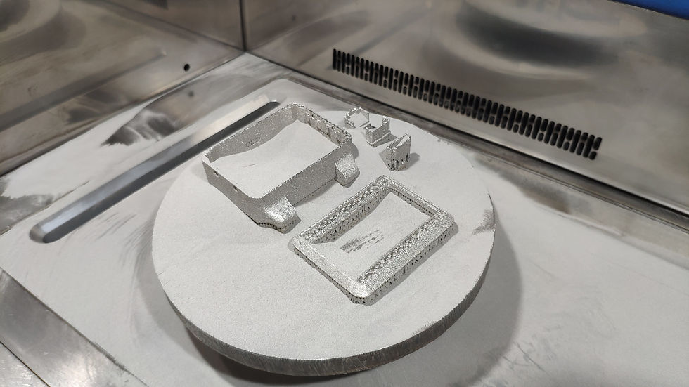
Loose powder removal
The powder bed is now cooled, and metal parts can be removed. During this step, loose powder is removed from the surface of the parts, and remaining surplus powder can be processed and reused for economical consumables management.
Sintering
The green parts are now moved into a furnace. At sintering temperatures, atomic diffusion at the surfaces of the metal particles binds them in a matrix that can exceed 96% solid density (depending on the type of material used). The polymer from the HP Metal Jet binding agent decomposes.
Finishing
The parts may now undergo post-processing to meet dimensional and surface finish requirements.
HP’s Metal Jet whitepaper describes the magic behind this technology in more detail and our ‘What can you make with a 3D printer?' article showcases some examples of innovative applications enabled thanks to HP Metal Jet technology.
Back to menu
Direct Metal Deposition (DMD) or Direct Energy Deposition (DED)
The DMD process involves melting metal material — typically cobalt, titanium, or chrome — as it is deposited, in the form of powders or wire.
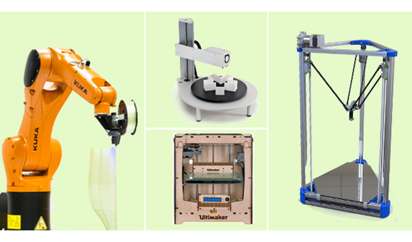
DMD consists of a multi-axis robotic arm with a nozzle that deposits metal powder or wire onto a surface. There are two key technologies in this category:
- Laser Engineered Net Shaping (LENS)
- Electron Beam Additive Manufacturing (EBAM)
The core difference between the two technologies is the heat source used to melt the material and form the solid part. LENS uses a laser head, while EBAM uses an electron beam. With DMD the nozzle is not fixed to a specific axis and can move in multiple directions. This means that the material can be deposited from any angle and is melted upon deposition.
Back to menu
Metal Extrusion
Similar to the Material Extrusion or Fused Deposition Modeling (FDM) and Fused Filament Fabrication (FFF) processes that use plastic materials, metal extrusion is a relatively new metal additive manufacturing method where a filament is heated, squeezed through a nozzle, and deposited onto a build plate to form an object layer by layer.
The filament is typically made up of metal particles embedded in a resin or thermoplastic. The nozzle moves in the x and y axes across the build platform, forming the part and the build platform lowers in preparation for the next layer.
Once fully formed, the part requires sintering in a furnace to remove any remaining plastic and sinter the metal particles together. Support structures are required for both the 3D printing and the sintering steps.
Want to continue learning?
What is metal 3D printing and how does it work?
What is metal 3D printing? How does this additive technology work? This article covers the basic principles of SLM (selective laser melting) and DMLS (direct metal laser sintering) and how these relate to the key benefits and limitations of 3D printing.
What is metal 3D printing? The differences between SLM and DMLS
Selective Laser Melting (SLM) and Direct Metal Laser Sintering (DMLS) are two metal additive manufacturing processes that belong to the powder bed fusion 3D printing family.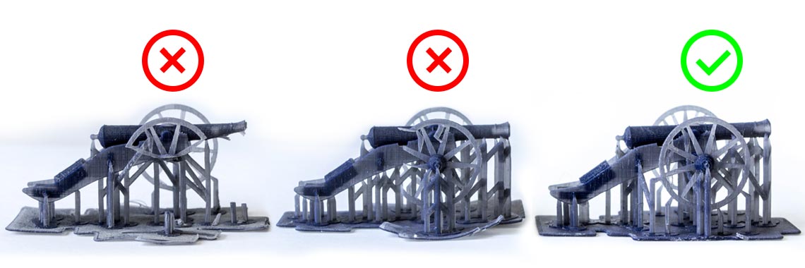 The two technologies have a lot of similarities: both use a laser to scan and selectively fuse (or melt) the metal powder particles, bonding them together and building a part layer-by-layer. Also, the materials used in both processes are metals that come in a granular form.
The differences between SLM and DMLS come down to the fundamentals of the particle bonding process (and also patents): SLM uses metal powders with a single melting temperature and fully melts the particles, while in DMLS the powder is composed of materials with variable melting points that fuse on a molecular level at elevated temperatures.
Essentially, SLM produces parts from a single metal, while DMLS produces parts from metal alloys.
The SLM and DMLS metal 3D printing processBoth SLM and DMLS are used in industrial applications to create end-use engineering products. In this article, we use the term metal 3D printing to refer to both processes in general and we describe the basic mechanisms of the fabrication process that are necessary for engineers and designers to understand the benefits and limitations of the technology.
There are other additive manufacturing processes that can be used to produce dense metal parts, such as Electron Beam Melting (EBM) and Ultrasonic Additive Manufacturing (UAM). Their availability and applications are limited though, so they won't be presented here.
Want to learn more about manufacturing metal parts?
Download our metal parts guide Our 3D printing services Our CNC machining services
How does metal 3D printing work?
The basic fabrication process is similar for both SLM and DMLS. Here's how it works:
-
The build chamber is first filled with inert gas (for example argon) to minimize the oxidation of the metal powder and then it is heated to the optimal build temperature.
-
A thin layer of metal powder is spread over the build platform and a high-power laser scans the cross-section of the component, melting (or fusing) the metal particles together and creating the next layer.
 The entire area of the model is scanned, so the part is built fully solid.
 -
When the scanning process is complete, the build platform moves downwards by one layer thickness and the recoater spreads another thin layer of metal powder. The process is repeated until the whole part is complete.
When the build process is finished, the parts are fully encapsulated in the metal powder. Unlike the polymer powder bed fusion process (such as SLS or MJF), the parts are attached to the build platform through support structures. Support in metal 3D printing is built using the same material as the part and is always required to mitigate the warping and distortion that may occur due to the high processing temperatures.
When the bin cools to room temperature, the excess powder is manually removed and the parts are typically heat treated while still attached to the build platform to relieve any residual stresses. Then the components are detached from the build plate via cutting, machining or wire EDM and are ready for use or further post-processing.
Want to design better parts for 3D print manufacturing?
Download our 3D printing design rules poster
What are the characteristics of metal 3D printing? Get to know SLM & DMLS
SLM & DMLS printer parameters
In SLM and DMLS almost all process parameters are set by the machine manufacturer. The layer height used in metal 3D printing varies between 20 to 50 microns and depends on the properties of the metal powder (flowability, particle size distribution, shape and more).
The typical build size of a metal 3D printing system is 250 x 150 x 150 mm, but larger machines are also available (up to 500 x 280 x 360 mm). The dimensional accuracy that a metal 3D printer can achieve is approximately ± 0. 1 mm.
1 mm.
Metal printers can be used for small batch manufacturing, but the capabilities of metal 3D printing systems resemble more the batch manufacturing capabilities of FDM or SLA machines than that of SLS printers. They are restricted by the available print area (XY-direction), as the parts have to be attached to the build platform.
The metal powder in SLM and DMLS is highly recyclable. Typically, less than 5% is wasted. After each print, the unused powder is collected, sieved and then topped up with fresh material to the level required for the next build.
Waste in metal printing comes in the form of support structures, which are crucial for the successful completion of a build but can increase the amount of the required material (and the cost) drastically.
Small batch manufacturing of a bicycle frame using SLM. Thank you to Renishaw and Empire Cycles for the photo.Layer adhesion
Metal SLM and DMLS parts have almost isotropic mechanical and thermal properties.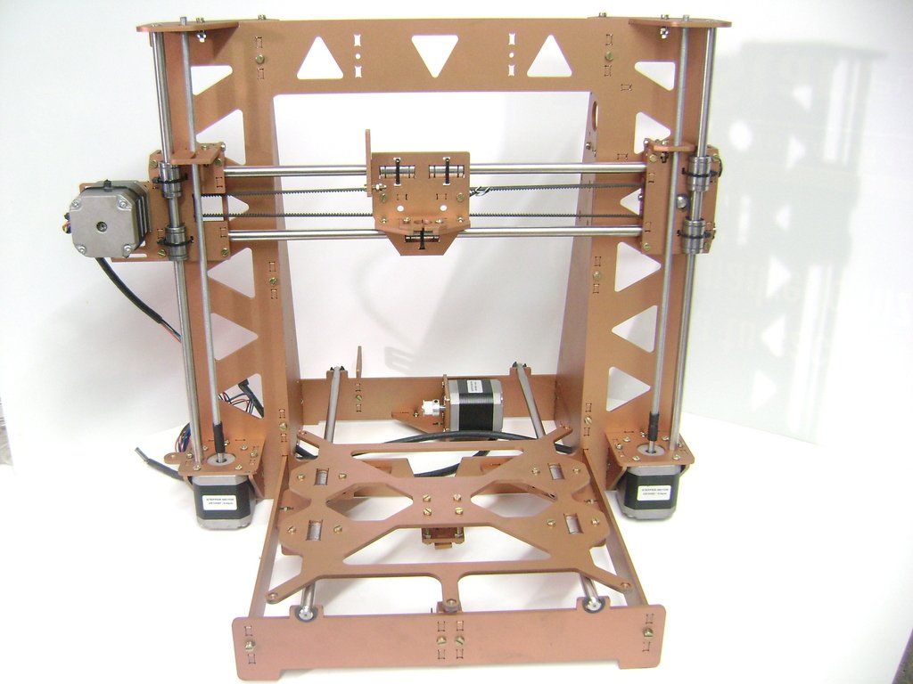 They are solid with very little internal porosity (less than 0.2 - 0.5% in the as-printed state and close to none after thermal processing).
Metal printed parts have higher strength and hardness and are often more flexible than parts that are manufactured using a traditional method. However, they are more prone to fatigue.
For example, take a look at the mechanical properties of the AlSi10Mg EOS metal 3D printing alloy and the A360 die-cast alloy. These two materials have a very similar chemical composition, high in silicon and magnesium. The printed parts have superior mechanical properties and higher hardness compared to the wrought material.
Due to the granular form of the unprocessed material, the as-built surface roughness (Ra) of a metal 3D printed part is approximately 6 - 10 μm. This relatively high surface roughness can partially explain the lower fatigue strength.
| AlSi10Mg (3D printing alloy) | A360 (Die cast alloy) | |
|---|---|---|
Yield Strength (0. 2% strain) * 2% strain) * | XY: 230 MPa Z: 230 MPa | 165 MPa |
| __Tensile Strength * __ | XY: 345 MPa Z: 350 MPa | 317 MPa |
| __Modulus * __ | XY: 70 GPa Z: 60 GPa | 71 GPa |
| __Elongation at break * __ | XY: 12% Z: 11% | 3.5% |
| __Hardness ** __ | 119 HBW | 75 HBW |
| __Fatigue Strength ± __ | 97 MPa | 124 MPa |
*Heat treated: annealed at 300 degrees Celsius for 2 hours
± Tested on as-built samples
Support structures & part orientation
Support structures are always required in metal printing, due to the very high processing temperature and they are usually built using a lattice pattern.
Support structures in metal 3D printing serve three different functions:
-
They offer a suitable platform for the next layer to be built upon.
-
They anchor the part to the build plate and they prevent warping.
-
They act as heat sinks, drawing heat away from the part and allowing it to cool at a more controlled rate.
Parts are often oriented at an angle to minimize the likelihood of warping and maximize part strength in critical directions. However, this will increase the amount of required support, the build time, the material waste and (ultimately) the total cost.
Warping can also be minimized using randomized scan patterns. This scanning strategy prevents the buildup of residual stresses in any particular direction and will add a characteristic surface texture to the part.
Since the cost of metal printing is very high, simulations are often used to predict the behavior of the part during processing.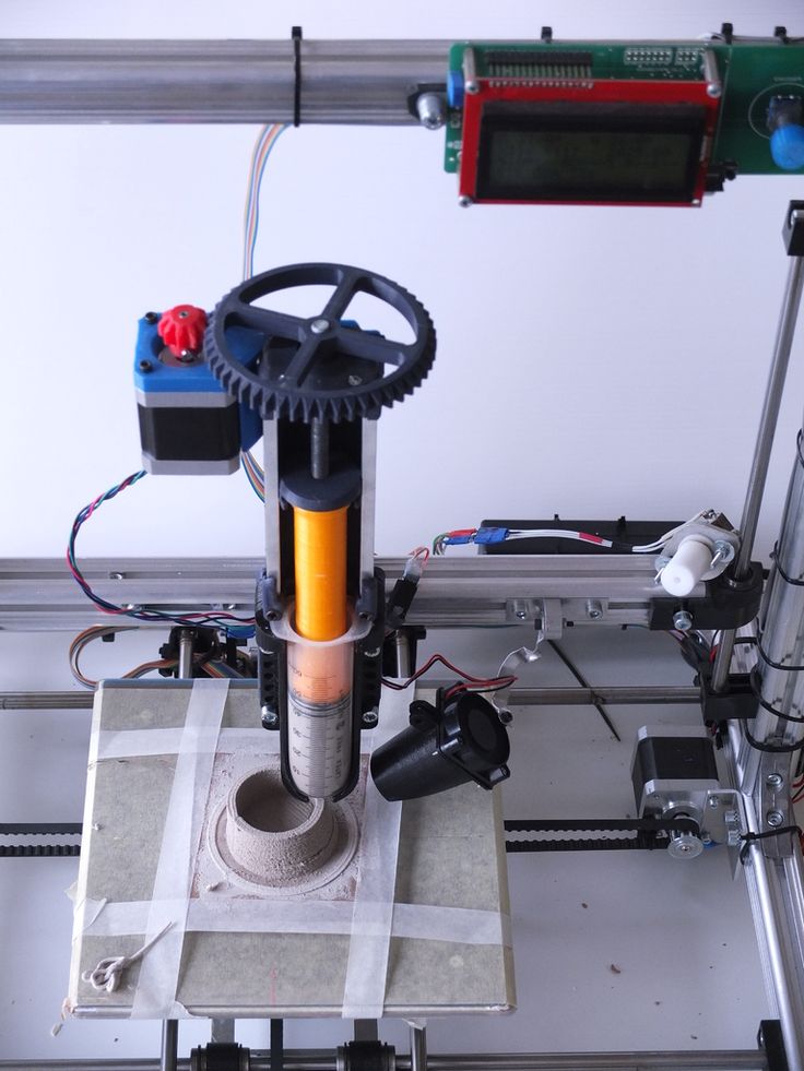 Topology optimization algorithms are also used not only to maximize mechanical performance and create lightweight parts but also to minimize the need for support structure and the likelihood of warping.
Hollow sections & lightweight structures
Unlike polymer powder bed fusion processes like SLS, large hollow sections are not commonly used in metal printing as support structures cannot be easily removed.
For internal channels larger than Ø 8 mm, we recommend using diamond or tear-drop cross sections instead of circular ones, as they require no support structures. More design guidelines on SLM & DMLS can be found in this article .
As an alternative to hollow sections, parts can be designed with skin and cores. Skin and cores are processed using different laser power and scan speed, resulting in different material properties.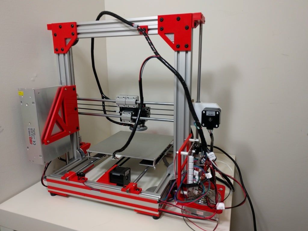 Using skin and cores is very useful when manufacturing parts with large solid sections, as they significantly reduce the print time and the likelihood of warping and produce parts with high stability and excellent surface quality.
Using a lattice structure is also a common strategy in metal 3D printing for reducing the weight of a part. Topology optimization algorithms can also aid in the design of organic, lightweight forms.
What are the common materials for 3D metal printing?
SLM and DMLS can produce parts from a large range of metals and metal alloys including aluminum, stainless steel, titanium, cobalt chrome and Inconel. These materials cover the needs of most industrial applications, from aerospace to medical. Precious metals, such as gold, platinum, palladium and silver can also be processed, but their applications are mainly limited to jewelry making.
Powder for metal 3D printing is, as you’d imagine, very expensive. For example, a kilogram of stainless steel 316L powder cost approximately $350 - $450.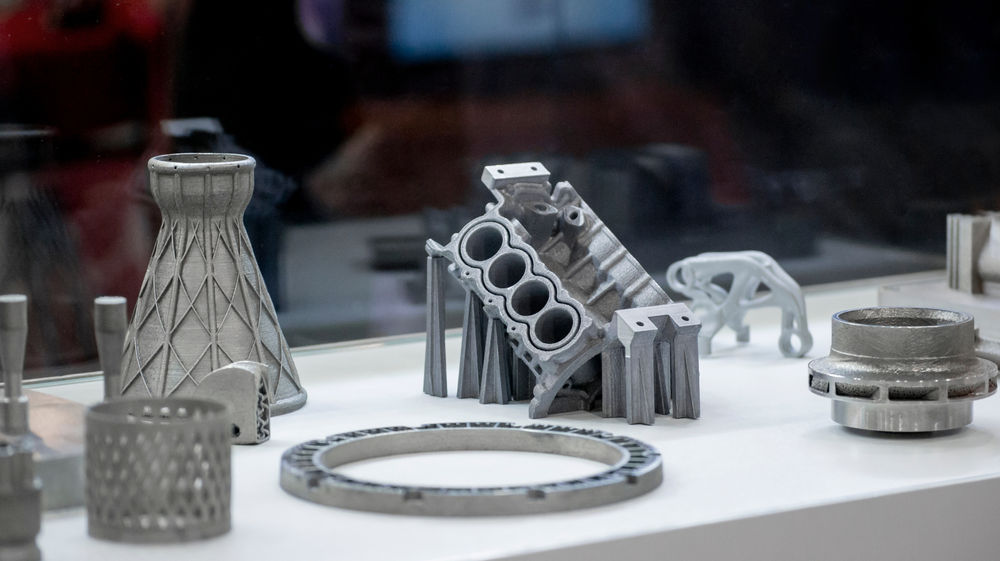 For this reason, minimizing the part volume and the need for support is key to keeping the cost as low as possible.
A key strength of metal 3D printing is its compatibility with high-strength materials, such as nickel or cobalt-chrome superalloys, that are very difficult to process with traditional manufacturing methods. Significant cost and time savings can be made, by using metal 3D printing to create a near-net-shape part that can is later post-processed to a very high surface finish.
| Material | Material
|------------------------------|
| Aluminium alloys | Good mechanical & thermal properties; Low density; Good electrical conductivity; Low hardness |
| Stainless steel & tool steel | High wear resistance; Great hardness; Good ductility and weldability |
| Titanium alloys | Corrosion resistance; Excellent strength-to-weight ratio; Low thermal expansion; Biocompatible |
| Cobalt-Chrome superalloys | Excellent wear & corrosion resistance; Great properties at elevated temperatures; Very high hardness; Biocompatible |
| Nickel superalloys (Inconel) | Excellent mechanical properties; High corrosion resistance; Temperature resistant up to 1200 degrees Celcius; Used in extreme environments |
| Precious metals | Used in jewelry making; Not widely available
Post-processing methods for metal 3D printing
Various post-processing techniques are used to improve the mechanical properties, accuracy, and appearance of the metal printed parts.
Compulsory post-processing steps include the removal of the loose powder and the support structures, while heat treatment (thermal annealing) is commonly used to relieve the residual stresses and improve the mechanical properties of the part.
CNC machining can be employed for dimensionally crucial features (such as holes or threads). Media blasting, metal plating, polishing, and micro-machining can improve the surface quality and fatigue strength of a metal printed part.
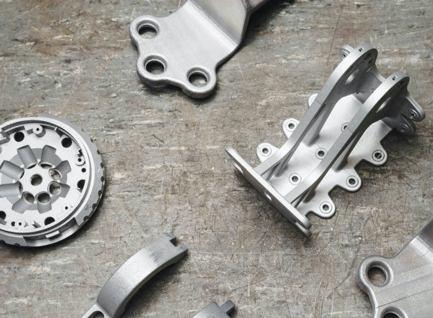
Satellite antenna manufactured using DMLS. Photo courtesy of Concept Laser and Optisys LLC.What are the benefits & limitations of metal 3D printing?
Here are the key advantages and disadvantages of metal 3D printing processes:
-
Metal 3D printing processes can be used to manufacture complex, bespoke parts with geometries that traditional manufacturing methods are unable to produce.
-
Metal 3D printed parts can be topologically optimized to maximize their performance while minimizing their weight and the total number of components in an assembly.
-
Metal 3D printed parts have excellent physical properties and the available material range includes difficult-to-process otherwise materials, such as metal superalloys.
-
The material and manufacturing costs connected with metal 3D printing are high, so these technologies are not suitable for parts that can be easily manufactured with traditional methods.
-
The build size of the metal 3D printing systems is limited, as precise manufacturing conditions and process control are required.
Already existing designs may not be suitable for metal 3D printing and may need to be altered.
The main characteristics of SLM and DMLS systems are summarized in the table below.
| Metal 3D printing (SLM / DMLS) | |
|---|---|
| __Materials __ | Metals & metal alloys (aluminum, steel, titanium) |
| Dimensional accuracy | ± 0. 1 mm 1 mm |
| Typical build size | 250 x 150 x 150 mm (up to up to 500 x 280 x 360 mm) |
| Common layer thickness | 20 – 50 μm |
| __Support structures __ | Always required |
Contact [email protected] or head to [Protolabs](https://www.protolabs.com/) to start 3D printing metal parts. For other 3D printing technoligies and CNC machining, you can upload a CAD file to our quote builder for a free, instant quote.
Our 3D printing service Our CNC machining service Get a free, instant quote
Ready to transform your CAD file into a custom part? Upload your designs for a free, instant quote.
Get an instant quoteHow metal 3D printers work. Overview of SLM and DMLS technologies. additive manufacturing. 3D metal printing.
Metal 3D printing.
 Additive technologies.
 SLM or DMLS: what's the difference?
Hello everyone, Friends! 3DTool is with you!
BLT metal 3D printer catalog
Selective laser melting ( SLM ) and direct metal laser sintering ( DMLS ) are two additive manufacturing processes that belong to the family of 3D printing using the powder layer method. The two technologies have much in common: they both use a laser to selectively melt (or melt) metal powder particles, bonding them together and creating a pattern layer by layer. In addition, the materials used in both processes are metals in granular form.
The differences between SLM and DMLS come down to the basics of the particle bonding process: SLM uses metal powders with a single melting point and completely melts the particles, while in DMLS the powder consists of materials with variable melting points. nine0014
Specifically:
SLM produces single metal parts while DMLS produces metal alloy parts.
Both SLM and DMLS technologies are used in industry to create final engineering products. In this article, we will use the term "metal 3D printing" to summarize the 2 technologies. We will also describe the main mechanisms of the manufacturing process that are necessary for engineers to understand the advantages and disadvantages of these technologies. nine0002 There are other manufacturing processes for producing dense metal parts, such as electron beam melting (EBM) and ultrasonic additive manufacturing (UAM). Their availability and distribution is rather limited, so they will not be presented in this article.
How 3D printing with SLM or DMLS metal works.
How does metal 3D printing work? The basic manufacturing process for SLM and DMLS is very similar.
1. The printing chamber is first filled with an inert gas (such as argon) to minimize the oxidation of the metal powder. It then heats up to the optimum operating temperature. nine0002 2. A layer of powder is spread over the platform, a powerful laser makes passes along a predetermined path in the program, fusing the metal particles together and creating the next layer.
3. When the sintering process is completed, the platform moves down 1 layer. Next, another thin layer of metal powder is applied. The process is repeated until the entire model is printed.
When the printing process is completed, the metal powder already has strong bonds in the structure. Unlike the SLS process, parts are attached to the platform via support structures. The support in metal 3D printing is created from the same material as the base part. This condition is necessary to reduce deformations that may occur due to high processing temperatures. nine0002 When the 3D printer's chamber cools down to room temperature, excess powder is removed manually, such as with a brush. The parts are then typically heat treated while they are still attached to the platform. This is done to relieve any residual stresses. They can then be further processed. The removal of the part from the platform occurs by means of sawing.
Scheme of operation of a 3D printer for metal.
In SLM and DMLS, almost all process parameters are set by the manufacturer. The layer height used in metal 3D printing varies from 20 to 50 microns and depends on the properties of the metal powder (fluidity, particle size distribution, shape, etc.). nine0002 The basic size of the print area on metal 3D printers is 200 x 150 x 150 mm, but there are also larger sizes of the working area. Printing accuracy is from 50 - 100 microns. As of 2020, metal 3D printers start at $150,000. For example, our company offers 3D metal printers from BLT.
metal 3D printers can be used for small batch production, but the 3D printing capabilities of such systems are more like those of mass production on FDM or SLA machines. nine0002 The metal powder in SLM and DMLS is recyclable: typically less than 5% is consumed. After each impression, the unused powder is collected and sieved, and then topped up with fresh material to the level required for the next production.
Waste in metal printing, are supports (support structures, without which it will not be possible to achieve a successful result). With too much support on the manufactured parts, the cost of the entire production will increase accordingly. nine0002
Adhesion between coats.
3D metal printing on BLT 3D printers
SLM and DMLS metal parts have almost isotropic mechanical and thermal properties. They are hard and have very little internal porosity (less than 0.2% in 3D printed condition and virtually non-existent after processing).
Metal printed parts have higher strength and hardness and are often more flexible than traditionally made parts. However, such metal becomes “tired” faster. nine0014
3D model support structure and part orientation on the work platform.
Support structures are always required when printing with metal, due to the very high processing temperatures. They are usually built using a lattice pattern.
Supports in metal 3D printing perform 3 functions:
• They form the basis for creating the first layer of the part.
• They secure the part to the platform and prevent it from deforming.
• They act as a heat sink, removing heat from the model. nine0014
Parts are often oriented at an angle. However, this will increase the amount of support required, the printing time, and ultimately the overall cost.
Deformation can also be minimized with laser sintering templates. This strategy prevents the accumulation of residual stresses in any particular direction and adds a characteristic surface texture to the part.
Since the cost of metal printing is very high, software simulations are often used to predict how a part will behave during processing. These topology optimization algorithms are otherwise used not only to increase mechanical performance and create lightweight parts, but also to minimize the need for supports and the likelihood of part distortion. nine0014
Hollow sections and lightweight structures.
An example of printing on a BLT 3D printer
Unlike polymer powder melt processes such as SLS, large hollow sections are not typically used in metal printing as the support would be very difficult to remove, if at all possible.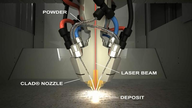
For internal channels larger than Ø 8 mm, it is recommended to use diamond or teardrop cross-sections instead of round ones, as they do not require support. More detailed recommendations on the design of SLM and DMLS can be found in other articles on this topic. nine0014
As an alternative to hollow sections, parts can be made with sheath and cores, which in turn are machined using different laser power and pass speeds, resulting in different material properties. The use of sheath and cores is very useful when making parts with a large solid section, as it greatly reduces printing time and reduces the chance of warping.
The use of a lattice structure is a common strategy in metal 3D printing to reduce part weight. Topology optimization algorithms can also help design organic lightweight shapes. nine0014
Consumables for 3D metal printing.
SLM and DMLS technologies can produce parts from a wide range of metals and metal alloys, including aluminum, stainless steel, titanium, cobalt, chromium and inconel.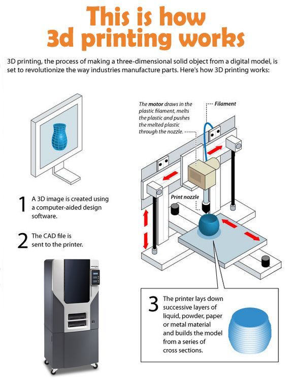 These materials meet the needs of most industrial applications, from aerospace to medical applications. Precious metals such as gold, platinum, palladium and silver can also be processed, but their use is of a minor nature and is mainly limited to jewelry making. nine0014
The cost of metal powder is very high. For example, a kilogram of 316 stainless steel powder costs approximately $350-$450. For this reason, minimizing part volume and the need for supports is key to maintaining optimal manufacturing cost.
The main advantage of metal 3D printing is its compatibility with high-strength materials such as nickel or cobalt-chromium superalloys, which are very difficult to machine with traditional methods. Significant cost and time savings can be achieved by using metal 3D printing to create a near-clean shape part. Subsequently, such a part can be processed to a very high surface quality. nine0002
Metal post-processing.
Various post methods. treatments are used to improve the mechanical properties, accuracy and appearance of metal printed products.
Mandatory post-processing steps include the removal of loose powder and support structures, while heat treatment (heat annealing) is typically used to relieve residual stresses and improve the mechanical properties of the part.
CNC machining can be used for critical features (such as holes or threads). Sandblasting, plating, polishing, and micro-machining can improve the surface quality and fatigue strength of a metal printed part. nine0014
Advantages and disadvantages of metal 3D printing.
Pros:
1. Metal 3D printing can be used to make complex custom parts, with geometries that traditional manufacturing methods cannot provide.
2. Metal 3D printed parts can be optimized to increase their performance with minimal weight.
3. Metal 3D printed parts have excellent physical properties, metal 3D printers can print a wide range of metals and alloys.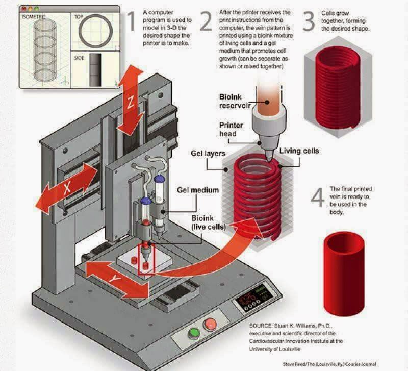 Includes difficult-to-machine materials and metal superalloys. nine0014
Cons:
1. Manufacturing costs associated with metal 3D printing are high. The cost of consumables is from $ 500 per 1 kg.
2. The size of the working area in metal 3D printers is limited.
Conclusions.
• Metal 3D printing is most suitable for complex, one-piece parts that are difficult or very expensive to manufacture using traditional methods, such as CNC.
• Reducing the need for building supports, will significantly reduce the cost of printing with metal. nine0002 • 3D printed metal parts have excellent mechanical properties and can be made from a wide range of engineering materials, including superalloys.
And that's all we have! We hope the article was useful to you.
Catalog of 3D printers for metal BLT
You can purchase metal 3d printers, as well as any other 3d printers and CNC machines, by contacting us:
• By email: Sales@3dtool. ru
ru
• By phone: 8(800)775-86-69
• Or on our website: http://3dtool.ru
Also, don't forget to subscribe to our YouTube channel:
Subscribe to our groups in social networks:
In contact with
how metal printing works on a 3D printer
Contents:
- Metal printing on a 3D printer
- How 3D technologies work
- Two main methods
- Video
Metal printing on a 3D printer (two main technologies)
The introduction of innovative technologies opens up new opportunities in various fields of human activity. A modern 3D printer for printing on metal allows you to print high-precision structural elements that are in demand in the space, engineering, and aviation industries.
How 3D technology works
3D parts are produced using different metal powder melting methods (using a laser). But the basic principle of operation remains unchanged, so any 3D printer prints with metal in several stages, these are:
- filling the build chamber with an inert gas to minimize the oxidation of the starting material;
- heating to the temperature required for the production process.
- distribution of powder over the surface of the build platform;
- 3D scanning of the cross section of the starting material with a laser beam;
- melting and sintering of particles, which makes it possible to obtain a hard layer;
- offset of the platform by the amount of the resulting layer for applying the next one (until the object is formed). nine0204
The moment the metal laser 3D printer completes the process, the product is completely covered in powder. Therefore, until the chamber cools down completely (to avoid deformations), the object on the platform is fixed by the support area.
Two main methods
A modern metal 3D printer can use one of the two most common technologies - selective laser beam melting (SLM) or direct laser sintering (DMLS). Among the main differences between the methods, the principle of gluing the component should be mentioned:
- SLM - occurs as a result of complete melting of the powder;
- DMLS - individual particles are sintered (at lower temperatures compared to SLM) without passing into a liquid substance.
Learn more