Hic 3d printer instructions
Resources - Hictop 3d printer
- Home
- Products
- 3D Printers
- Parts and Accessories
- Filaments
- PLA
- ABS
- Flexible
- Nylon
- HIPS
- PET-G
- Wood
- Resources
- Firmware
- User's Manual
- STL Files
- Drivers and Softwares
- Troubleshooting
- After-Sales Policies
- Media
- Forum
- Youtube
- Contact
- My Account
- Continue Shopping
- Your Cart is Empty
Get the latest firmware for your HicTop 3D Printer!
GET UPDATE
Download Users Manual for your HicTop 3D Printer!
GET MANUAL
Stay on the loop. Get the latest and hottest 3D model for your next project
VIEW PROJECTS
Download the up to date drivers and software for you HicTop 3D printer
DRIVERS AND SOFTWARES
HICTOP HICTOP Prusa I3 3D Printer
| Brand | HICTOP |
| Machine type | 3D Printer |
| Technology | FDM (Fused Deposition Modeling) |
| Materials | PLA, ABS, Nylon, Bronze PLA, Copper, HIPS, FLEX (Elastic TPE), Wood PLA, Copper PLA, Rubber-like (TPU) |
| Website | http://www.hic3dprinter.com/productshow.asp?ArticleID=0&id=15&cid=001 |
| Average Price | Contact manufacturer |
Specifications:
Extruder quantity: 1
Printing size: 270*200*170mm
Layer sickness: 0.1-0.4mm
SD-card: Support
LCD screen: Yes (Support off-line printing)
Printing speed: 120mm/s
Standard extruder dimeter: 0.4mm
Extruder temperature: 250
Hot bed temperature: 110
Hot bed parts material: Acrylic,aluminum,PCB
XY axis positioning accuracy: 0.011mm
Z axis positioning accuracy: 0.004mm
Printing material support: ABS, PLA
Printing material diameter: 1.75mm
Software language: English
Date import format: STL, G-Code
Device dimension: 430*505*380mm
Device weight: 8kg
Packing dimension: 470*470*330mm
Packing weight: 11KG
Power supply: 12V
Operating system: XP, WIN7, MacOS
Printing software: ReplicotorG
Working condition Temp: 10-30 degree, Humidity:20-50%
Reviews 5.
 0 1 reviews
 Print Quality
Reliability
Ease Of Use
Failure Rate
Running Expenses
Software
Build Quality
Customer Service
Community
Show reviews Hide reviews
Aug 4, 2022
Prusa Mini+ is a solid entry level printer that was ready right out the box. I have printed several structural items to replace broken parts around the house. Customer support from Prusa is also great to use. No issue with PLA or PETG even for a beginner. Would recommend for anyone wanting an out of the box ready 3D Printer.
instruction how to work from scratch for beginners and dummies, how
looks likeThree-dimensional printing has become increasingly introduced into our daily lives. Thanks to new technologies, it has become possible to easily print from a small detail to a large building. The range of products is also pleasing - today you can find a lineup that includes both affordable devices and more expensive ones. But how to work with a 3D printer? This is a completely normal question that any beginner will have, it is for this reason that we will try to answer it as simply and accessible as possible.
What is a 3D printer and how does it work?
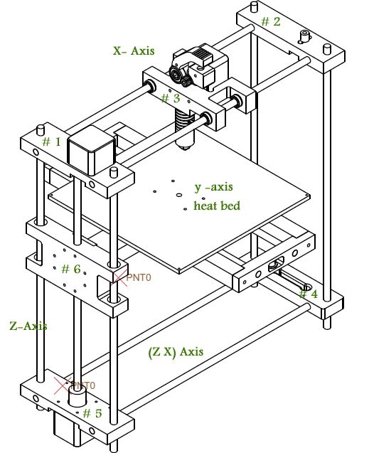
The 3D device consists of the printer itself and a computer that controls all processes. The principle of operation of such a design is to create 3D models by superimposing layers of liquid material.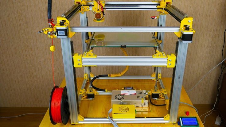 There are a large number of printer models - from large industrial ones to compact ones, but they all have the same principle of operation and component parts:
- Extruder - the print head through which the thread passes. The head heats the thread to a semi-liquid state and evenly supplies the material to the working surface.
- Work surface - a printing platform on which a 3D model is formed.
- Motors - mechanisms responsible for the accuracy of movement and speed of printing.
- Sensors are electronic devices that limit moving parts to specified coordinates.
- The frame is the structure that connects all parts of the printer.
How a 3D printer works: features
Work with the aim of building a three-dimensional model begins with a sketch, which is created in a special program. After that, the software independently generates a plan for the movement of the print head and a print sequence. The 3D model is reproduced by strongly heating the plastic and distributing it evenly.
3D printers are used in many areas. Let's list some of them:
- Architecture - creation of models of buildings.
- Medicine - dental prosthetics, making models of organs for study.
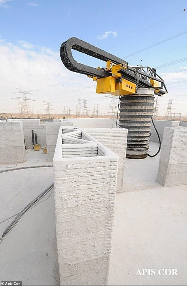
- Construction - production of houses using 3D printing technology.
- Education - a visual aid for learning 3D printing.
- Automotive - creation of tuning parts, prototype layouts and other products.
This is a small list of industries where 3D printing is actively used. Today, almost every entrepreneur and just an enthusiastic person can afford a printer.
The following printers are distinguished by design features:
- RepRap - self-reproducing printers that can create their own copies.
- DIY-kit - the device comes disassembled with instructions, the assembly of which will take a sufficient amount of time.
- Completed - Models are delivered assembled and ready to use.
- Commercial and Industrial - devices capable of printing metal, concrete, polymers and other materials.
How to use a 3D printer: tips for beginners, where to start
Mastering the technique of 3D printing is not difficult if you follow the recommendations and tips. Especially for those who plan to learn the basics of 3D modeling, an up-to-date list of questions and detailed answers to them has been prepared.
Printer Installation
To begin, you will need to carefully unpack the box and remove any stops. The next step is to install the printer on the surface using the building level. This will allow you to place the device as evenly as possible, which will provide better printing.
Note. Some 3D printers come with a level for installation.
Next, you will need to connect the printer to your computer and install the necessary drivers. The software disc comes with the 3D device.
Preparation for work
To get started, you need to calibrate the working surface - without this, printing quality products is impossible.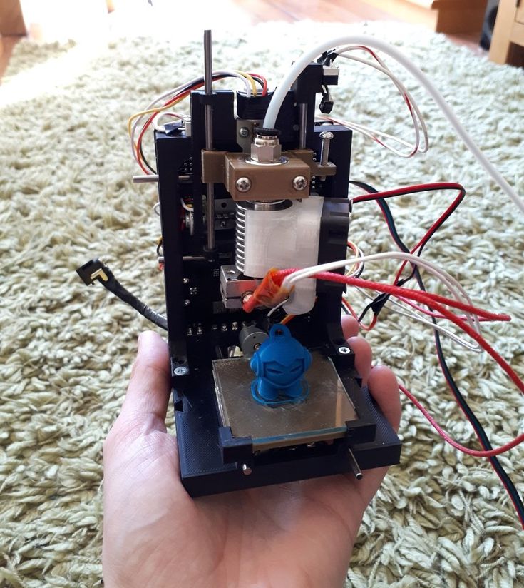 This process is carried out automatically or manually. The attached instructions have detailed information on how to perform manual calibration.
Extruder patency test
The next important step is setting up the extruder. First of all, you will need to check its nozzle. If the printer has already been used, the nozzle should be cleaned of solidified particles that will interfere with the throughput of the material. Refueling the 3D printer The thread is fed into the extruder directly from the spool. But there is one caveat - for this you must first warm it up. To thread the thread, you will have to make a small effort in order to loosen the presser mechanism.
Working with models
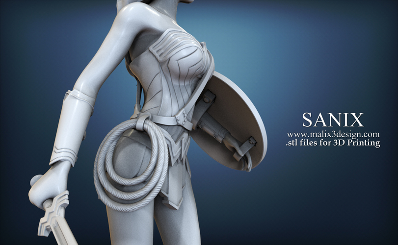
Models can be created using a variety of 3D modeling programs. The process of manufacturing three-dimensional parts is creative, requiring careful preparation. The better and more detailed the model is drawn, the better the 3D layout will be at the output.
Start printing
After creating the model in the program and preparing the printer for work, you need to send the file for printing and wait for the result.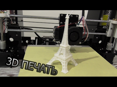 The print speed varies depending on the printer model and specifications, as well as the media used.
Processing the finished product
3D printed products usually do not please the user with an ideal appearance: the parts have an uneven surface. But this is typical for models of 3D printers on FDM, SLA and DLP devices, which are distinguished by higher print quality. Owners of FDM printers should not despair - a simple processing of products will give products an attractive appearance and make the surface smooth.
Several powerful ways to post-process 3D printed parts:
- Mechanical - carried out by sanding the surface with sandpaper or a special sponge for grinding.
- Chemical - Surface treatment with aggressive solvents such as acetone and dichloroethane.
- Mixed - In this case, the above two processing methods are used.
What are the possible errors and how to avoid them?
Even a novice can master the technology of 3D printing, but, despite this, the production of the first products causes excitement for the user.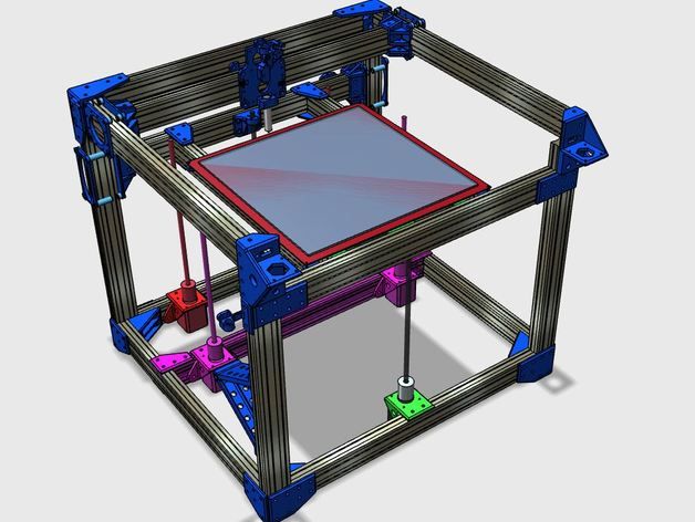 Simple operation, detailed instructions and recommendations on the Internet will allow everyone to deal with almost any printer model. But there are a few useful life hacks, the knowledge of which will help you avoid typical beginner mistakes:
- Calibrate and test the 3D printer before starting work.
- Be sure to use the correct file extension for quality printing.
- Do not remove the finished product from the printer immediately after it has been processed: this may damage the part and cause defects.
- If errors occur during the 3D printing process, try restarting the device - this usually helps.
- If restarting the printer still does not help, try changing the settings or re-entering the model.
- When assembling the 3D printing devices, follow the enclosed instructions carefully.
- Use only the correct materials for your 3D printer.
- Subscribe to useful 3D printing channels and articles.
Following the above tips will allow you to set up your 3D printer, get it ready for operation and, most importantly, print your first 3D products.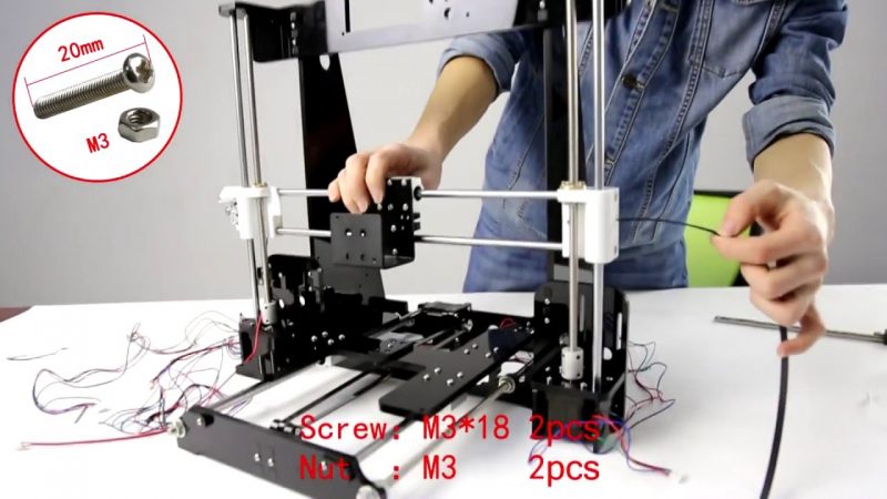 Choose a model according to your budget and capabilities, and it will not be difficult to master the basics of 3D modeling and get the first details if you follow the instructions and recommendations.
- March 21, 2021
- 7719
Get expert advice
Instructions for setting up all the mechanics of a 3D printer: from belts to speeds
The quality of the printed models directly depends on the mechanics of the printer, namely on its correct settings. Any elements of the printer wear out over time, so the printer must be set up at least once every 5-6 kg of printed filament. With the help of the short instructions described in this guide, you can quickly and easily set up the mechanics of your printer: belt tension, motor current, motor steps, acceleration, jerk and speed.
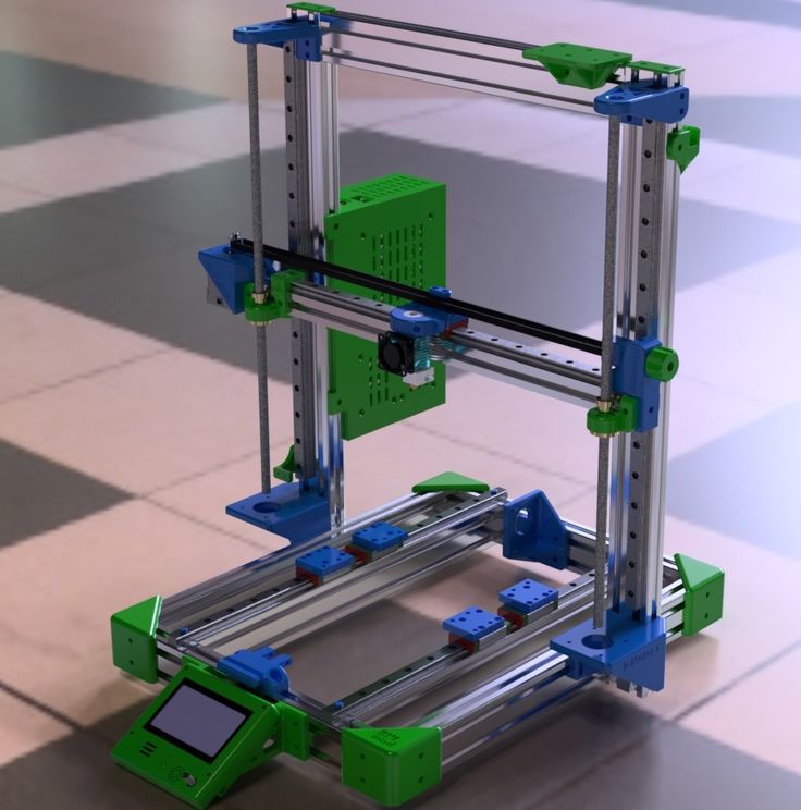
Mechanics includes
3D printers of any design always contain the same things: Axes and rails along which the elements of the printer move and motors with belts that set these elements in motion. In a classic printer design, there are at least 3 motors (one for each axis), 3 rails (one for each axis) and an electronics board that controls the motors. The latter can hardly be called part of the mechanics, but since it controls the engines, it also indirectly affects the quality of the model.
Printing defects due to mechanical problems
Before changing anything in the printer, you need to decide what exactly needs to be configured. Often defects are visible visually. Our blog has an article about most printing defects, which details the reasons for their occurrence. The following is a list of defects and what element of mechanics they are associated with:
-
Layer shifting - Belts, Motor current, Guides
-
Ringing - Guides, Speed
-
Incorrect model geometry - Guides, Motor steps, belts
As you can see, all the above problems do not interfere with the printing process itself, but the result leaves much to be desired.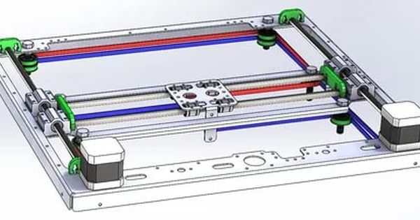 Sometimes mechanical errors can completely stop the printer from working. Therefore, it is better not to take the situation to extremes and, if any problems arise, immediately start checking and configuring the 3D printer.
How to save settings
To fix some defects, you need to change the printer software settings. Therefore, before adjusting the mechanics, it is necessary to understand how to properly store the settings inside the printer. There are 3 ways to do this:
All settings are located in the corresponding menu of the printer
Depending on your firmware, this manual will indicate code sections for MARLIN firmware in the configuration.h file
We first enter the parameters into the printer and then store them in EEPROM - the internal memory of the microcontroller. Or paste all the necessary settings at the beginning of GCODE. To learn how to do this, read our article on working with GCODE and creating macros.
To save to EEPROM, you need to send the printer a command to change some value (which can also be inserted into the initial GCODE), and then send the M500 command (save the current settings to permanent memory).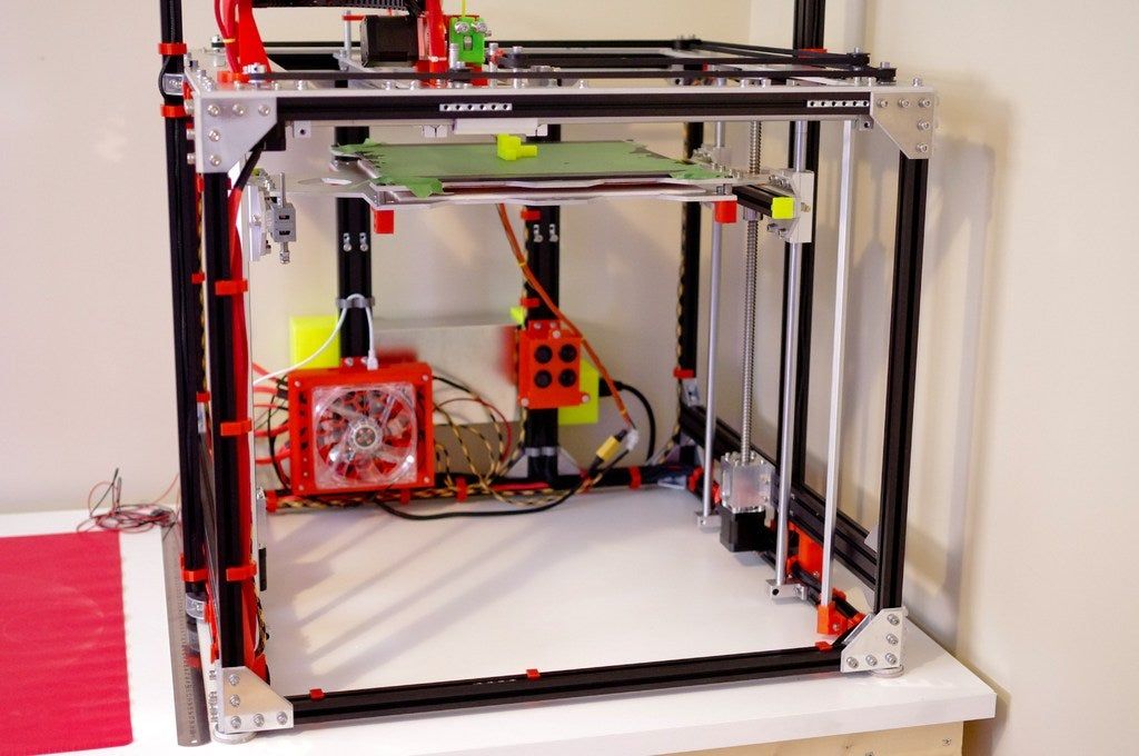 The EEPROM function must be enabled in the firmware, for this you need to remove two slashes in the line:
//#define EEPROM_SETTINGS
Whichever option you choose, you should be careful when using any commands. You will not be able to harm the printer in any way when changing the settings, but if you make a mistake, you will have to look for the cause of possible further problems for a long time.
Setup instructions
Now you can start setting up the printer itself. If you decide to set several parameters at once, then it is better to use the order of adjustments as in the article, since some of the settings are related to each other and if you use the wrong order, adjusting one element of the mechanics will override the settings of another element. For example, you should not adjust the motor steps before tightening the belts, as changing the length of the belts will change the "true" steps per millimeter of the motors. Also, before setting up, you must make sure that there are no backlashes in the printer frame, tighten all belts.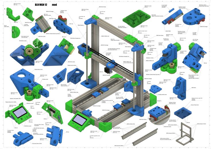
Belts
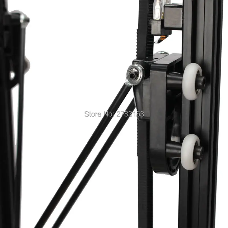
The first thing to start setting up the printer is the belts. They directly affect the geometry of the model and, when pulled too much, they cause a lot of problems: displacement of layers, changes in geometry, ripples. First you need to make sure the belt is intact. To do this, look at the entire belt, especially the areas where the belts bend. If the belt has outlived its usefulness, then you can see a section of the belt where the distance between the teeth has greatly increased and a metal wire (cord) is visible between them. This means that it's time to completely change the belt.
Broken belt with broken cords
If the belt is intact or you have already replaced it, then you can proceed to the next step. Depending on the design of your printer, you need to move the roller through which the belt passes. The tension should be such that the carriage or table moves effortlessly, but at the same time, when moving quickly, the belt should not slip the teeth on the motor gear.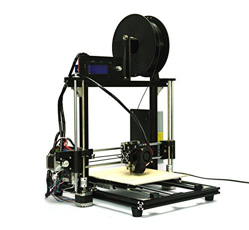 Adjust the tension of the belts on each axis of the printer using this method.
Tip: if your printer came with a belt tensioner in the form of a spring attached to the belt itself, remove it. Due to the flexibility of this tensioner, printing defects will occur, such as protruding corners on the model. It is better to adjust the belt without using this tensioner.
Belt tensioner
Current motors
As we know from the school physics course, the power of the engine depends on the voltage and current strength. Since the voltage on all printer electronics is the same everywhere, the only thing that can be changed is the current on the motor. More precisely, it should be said the maximum current that the driver will supply to the motors. To change this limit, you need to climb inside the case and find the printer board. On it you will see the printer driver. We are interested in a small potentiometer on the driver itself (in the picture below it is indicated as a tuning resistor).
Potentiometer location example on driver
For adjustment, you will need a voltmeter and a small Phillips or flathead screwdriver. Before proceeding further, it is necessary to calculate the maximum current supplied to the motors. Different formulas are used for different drivers, the most popular ones will be listed in the table below:
| Driver name | Formula | Explanations |
| A4988 | Vref = Imax * 1.25 for R100 | To understand which formula to use, you need to find a resistor with the signature R100 or R050 on the driver. They are located next to the driver chip. |
| DRV8825 | Vref = Imax / 2 | |
| LV8729 | Vref = Imax / 2 | |
| TMC2208 TMC2100 TMC2130 | Vref = Imax * 1. | One formula for all drivers |
 41
41 The value of the maximum current (Imax) depends on the motor controlled by the driver. This can be found in the engine specification or on the sticker on it. The following are the currents for the most popular motor models:
17HS4401 - current 1.7 A
17HS8401 - current 1.8 A
17HS4402 - current 1.3 A
Substituting the value into the formula, we get the Vref value for the maximum current supplied to the motor. But at this value, the engine will get very hot, so the resulting Vref value must be multiplied by 0.7. For example, for a motor with a maximum current of 1.5 A and a TMC 2208 driver:
Vref=1.5*1.41*0.7=1.48V
Now the resulting value can be used when configuring on the printer itself. To do this, disconnect the wires going to the motors, turn on the printer and place one voltmeter probe in the center of the trimmer, and the second probe to the negative terminal on the power supply (you can also use the negative terminal on the printer board and the contact on the driver, labeled as GND). You will see some value on the voltmeter screen. Turn the trimmer clockwise to decrease the Vref value and counterclockwise to increase it.
Attention: you should not specify a Vref value higher than the maximum calculated for your engine! Otherwise, the engine will soon break down!
Once you have adjusted the value on the drivers, you can turn off the power to the printer, connect the motor wires, and put the case back together. This completes the driver setup.
Motor steps
When setting up motor steps, you will need a ruler. For convenience, you can use the program Repetier-Host. The adjustment for each of the three axes occurs according to the same algorithm:
-
Set the caret to zero coordinates (Autohome or G28)
-
Move the carriage some distance
-
We measure how far the carriage has traveled
-
We calculate the correct number of steps per millimeter using the formula:
True steps per millimeter = current steps per millimeter * reported distance / distance traveled
For example, if the printer was set to 100 steps/mm, we tell the printer to move 80mm and the printer travels 87.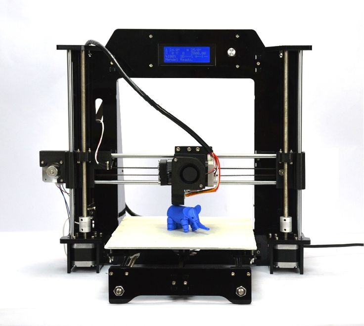 5mm. Then the correct steps per millimeter would be 100 * 80 / 87.5 = 91.42 steps/mm. For the convenience of measurements, you can fix a ruler on the table, and a thin object, such as a needle or pin, on the carriage. Then it will be possible to accurately measure the distance traveled. The extruder uses a partially different algorithm to measure distance:
-
Inserting plastic into the extruder
-
Cut it right at the outlet
-
We give the printer a command to stretch the plastic a certain distance (at least 100 millimeters)
-
Cutting plastic again
-
We measure the length of the resulting piece of plastic
-
We use the formula from the previous algorithm
Next, the settings data must be inserted into the firmware in the line:
#define DEFAULT_AXIS_STEPS_PER_UNIT {X,Y,Z,E0}
X,Y,Z and E0 should be replaced by the steps per millimeter for each of the axes, respectively. Otherwise, you need to insert this line into the initial GCODE:
M92 Ennn Xnnn Ynnn Znnn
Instead of nnn in each of the parameters, you must substitute the steps per millimeter for each axis. If you want to adjust the steps only for not all axes, then you can remove unnecessary parameters.
Acceleration
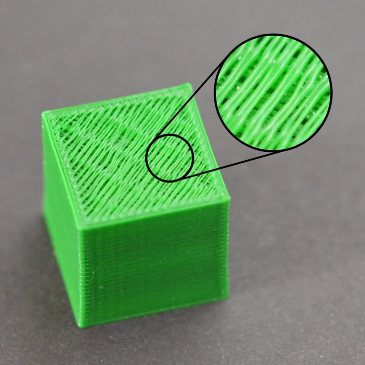
This parameter is responsible for the rate of change of speed. That is, how fast the printer will change its speed. This affects the nature of the movement of the hot end relative to the table. If the acceleration is too small, then the printer will print slowly, if it is too large, then the outer surface of the model will have visual defects: fading waves will be visible near each of the corners, as in the picture below.
To set up acceleration, you need to follow simple steps:
-
Cut a model of a standard test cube with a wall thickness equal to one nozzle diameter, without filling and top layers, bottom 2-3 layers;
-
Open GCODE file in notepad;
-
Find the G28 command at the very beginning and insert the line data after it:
M201 X5000 Y5000
M204 P500 T500
-
Save the changes, print the model according to the received GCODE and note at what parameters P and T it was printed;
-
Open the same GCODE file and change the P and T values on the second line, adding 500 to each;
-
Repeat steps 4-5 at least 3 times;
As a result, you will get several test cubes, some of which will show waves at the corners.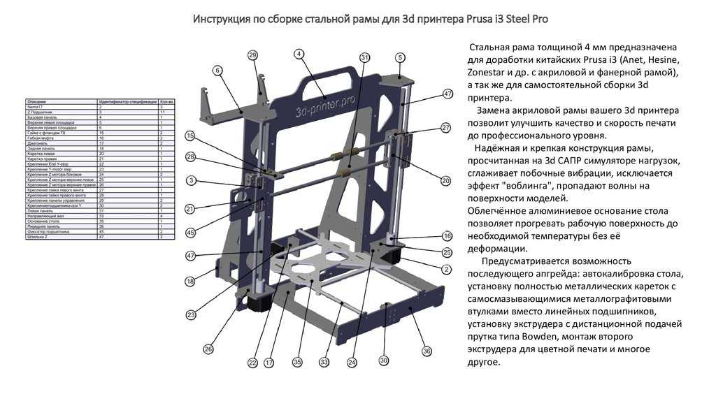 Choose the cube that is printed with the highest P and T parameters, but that no waves can be seen on it. The number in parameter P will be the desired acceleration value. To save this value, you need to find 2 lines in the firmware:
#define DEFAULT_MAX_ACCELERATION {X,Y,Z,E0}
#define DEFAULT_ACCELERATION {nnn}
Instead of X and Y, you should put an acceleration twice as high as found earlier. And instead of nnn, you need to put the acceleration value found earlier. Otherwise, you need to insert a line in the initial GCODE:
M204 Pnnn Tnnn
In the parameters P and T, you need to put the value of the found acceleration. After that, the acceleration setting can be considered complete.
Jerk
A jerk indicates the speed with which to start accelerating. It affects the model in a similar way as acceleration: it creates ripples around the corners of the model. But it also increases the protrusion of the corners if the jerk is too small. The jerk setting is also similar to the acceleration setting:
-
Cut a model of a standard test cube with a wall thickness equal to one nozzle diameter, without filling and top layers, bottom 2-3 layers.
-
Open GCODE file in notepad
-
Find the G28 command at the very beginning and insert the line data after it:
M205 X5 Y5
-
Save the changes, print the model according to the received GCODE and note at what X and Y parameters it was printed
-
Open the same GCODE file and change the X and Y values on the second line, adding 2 to each
-
Repeat steps 4-5 at least 3 times
As a result, you will get several cubes. Find a non-rippled cube printed at the highest X and Y settings. This will be the jerk value for your printer. To save them, you need to find the line in the firmware:
#define DEFAULT_XJERKnnn
#define DEFAULT_YJERKnnn
It is necessary to substitute the jerk values for the X and Y axes, respectively.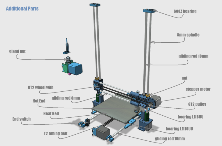 Otherwise, you need to substitute the command in the starting GCODE:
M205
Instead of nnn, you need to substitute the jerk value found earlier. This completes the jerk setting.
Speed
In fact, there are many different speed parameters, the values \u200b\u200bof which vary greatly. Let's take a look at the main ones:
This parameter is responsible for moving the nozzle without extruding plastic. The value is in the range from 80 to 120 mm/s. Limited only by the maximum speed at which the motors can rotate. Does not affect the model
This speed is important because it indirectly affects the adhesion of the model to the table. Usually lies between 15 and 30 mm/s
-Print speed of inner walls
Usually set to about 60 mm/s, it only affects the strength of the model. Depends on the maximum amount of plastic that the extruder can push through the nozzle
-Speed of printing outer walls
Usually about half the printing speed of the inner walls (30 mm / s).