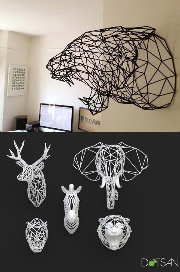
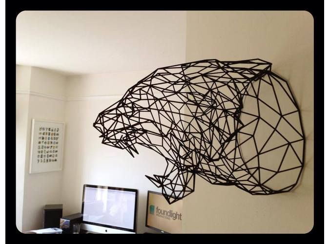
3D printed wireframe
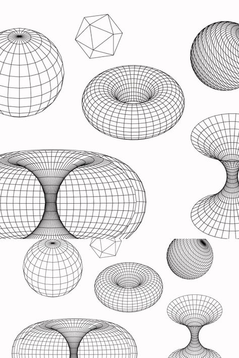
WirePrint: Fast 3D Printed Previews
WirePrint:
Fast 3D Printed Previews.
Figure 1: WirePrint prints 3D objects as wireframe previews. By extruding filament directly into 3D space instead of printing layer-wise, it achieves a speed-up of up to a factor of 10, allowing designers to iterate more quickly in the early stages of design. WirePrint achieves its maximum speed-up on (a) 3D printers based on the delta design, but also works on traditional Cartesian-based printers such as the PrintrBot shown in (c). Even though considered a rapid prototyping tool, 3D printing is so slow that a reasonably sized object requires printing overnight. This slows designers down to a single iteration per day. With WirePrint, we propose to instead print low-fidelity wireframe previews in the early stages of the design process. Wireframe previews are 3D prints in which surfaces have been replaced with a wireframe mesh. Since wireframe previews are to scale and represent the overall shape of the 3D object, they allow users to quickly verify key aspects of their 3D design, such as the ergonomic fit. To maximize the speed-up, we instruct 3D printers to extrude filament not layer-by-layer, but directly in 3D-space, allowing them to create the edges of the wireframe model directly one stroke at a time. This allows us to achieve speed-ups of up to a factor of 10 compared to traditional layer-based printing. We demonstrate how to achieve wireframe previews on standard FDM 3D printers, such as the PrintrBot or the Kossel mini. Users only need to install the WirePrint software, making our approach applicable to many 3D printers already in use today. Finally, wireframe previews use only a fraction of material required for a regular print, making it even more affordable to iterate. Introduction The recent development in rapid prototyping tools, such as 3D printers [5] allows users to prototype one-off objects and to iterate over designs. Unfortunately, 3D printers are inherently slow, because they fabricate objects voxel-by- voxel and layer-by-layer. A reasonably sized object thus tends to print overnight, slowing designers down to a single iteration per day [15].
 We therefore argue that the process of how 3D printers are used for quick design iteration is not yet optimal. In other disciplines, such as in user interface design, designers achieve a fast and efficient process by iterating from low-fidelity prototyping techniques to high-fidelity techniques. In order to allow designers to iterate quickly, low-fidelity techniques, such as sketching and paper prototyping, give priority to speed over functionality. This trade-off pays off in the early phases of design because it encourages the quick exploration of several versions before committing further resources, eventually leading to a better design [2]. We argue that the same principle should apply to 3D printing – a concept we call low-fi fabrication. In contrast to the traditional workflow, in which the 3D model is always fabricated as slow hi-fidelity print, low-fi fabrication fabricates all intermediate versions as fast low-fidelity previews. Only at the end, when the design is finished, the complete 3D model is printed as hi-fidelity (Figure 2).
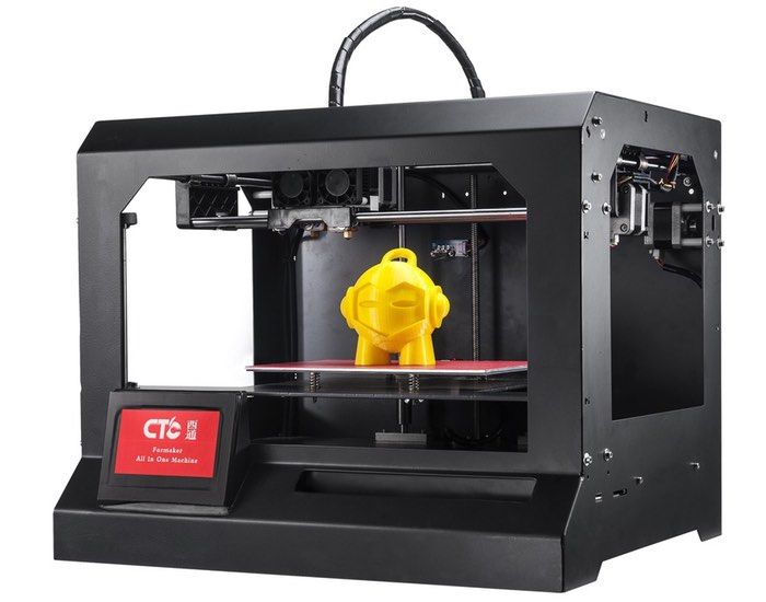
 One low-fi fabrication approach is faBrickation [15]—a system that achieves speed-up by substituting less crucial parts of a 3D model with Lego bricks. Unfortunately, faBrickation requires users to manually assemble the bricks, so is effectively trading in printing time for manual effort. In this paper, we present a low-fi fabrication approach that is not only fast, but also fully automated. The key idea is to print the 3D object as a wireframe preview, i.e. a 3D print in which surfaces have been replaced with a wireframe mesh. Our approach runs on standard FDM 3D printers, such as the PrintrBot or the Kossel mini (rather than on a 5 axis robot arm [12])—users only need to install the WirePrint software. Additional cooling around the print head helps to maximize the printing speed. Figure 2: Low-fi fabrication: all intermediate versions are fabricated as fast low-fidelity prints. Only the final version is fabricated as hi-fidelity. WirePrint Figure 1a shows the 3D wireframe of a bottle in the process of being printed using WirePrint.
 WirePrint takes 14 minutes to 3D print the bottle (on our Kossel mini 3D printer [3]). This is 8.5 times faster than a traditional full-detail 3D print on the same 3D printer. Figure 3: Iterating a design using WirePrint: (a) adjusting the model in a 3D editor, (b) converting it in the WirePrint software, (c) reprinting, (d) testing. 3D wireframes created with WirePrint allow designers to quickly validate the high-level design of a 3D object, such as its ergonomic fit. After examining the bottle shown in Figure 1b, the designer notices that the bottle does not yet rest comfortably in the hand—the designer thus decides to change the model. Figure 3 illustrates the typical workflow when iterating over a design using WirePrint. (a) The designer adjusts the thickness of the bottle in a 3D modeling program, (b) converts the model in the WirePrint software, (c) reprints it, and (d) tests its fit in the hand again. The designer may repeat the process until the bottle fits well.
 At this point, the designer moves on to the details of the design, until finally 3D printing the bottle (1:59 hours). WirePrint allows this design process, including its iterations, to be completed within only a couple of hours. How WirePrint works WirePrint converts a 3D object into a wireframe representation by (1) slicing the 3D model along its vertical axis into horizontal slices and (2) extracting the contours. It then (3) fills the space between slices with a zigzag pattern. Figure 4: WirePrint’s layouts consist of an alternation between (a) contour and (b) zigzag. As illustrated by Figure 4, WirePrint fabricates objects by alternating between (a) printing a contour and (b) creating one layer of the zigzag pattern on top of the contour. Unlike traditional 3D printers that stack filament on filament, WirePrint creates its layers by moving the print head up and down repeatedly. If a slice contains multiple disconnected contours, such as the telephone receiver shown in Figure 5, WirePrint prints all contours located on the same slice first (i.
![]() e. the contour of the left ear cap, then the contour of the right ear cap), before moving up to the next slice. Figure 6 illustrates why WirePrint uses this particular contour-plus-zigzag approach. The main challenge in printing wireframes is that the print head has to respect already printed material in order to prevent collisions. Each bit of printed material results in additional volume becoming inaccessible Figure 5: Multiple contours are printed one at a time. Figure 6 describes the consequences that result from volume becoming inaccessible: (a)Two vertical edges, for example, need to be spaced at least one print head diameter apart. (b) While it is always possible to print upwards, we cannot print downwards steeper than the slant of the print head itself, as steeper edges can cause the slanted tip of the print head to collide with what is just being printed. In the case of our 3D printer (a Kossel Mini [3]), for example, this threshold angle is 32 degrees.
e. the contour of the left ear cap, then the contour of the right ear cap), before moving up to the next slice. Figure 6 illustrates why WirePrint uses this particular contour-plus-zigzag approach. The main challenge in printing wireframes is that the print head has to respect already printed material in order to prevent collisions. Each bit of printed material results in additional volume becoming inaccessible Figure 5: Multiple contours are printed one at a time. Figure 6 describes the consequences that result from volume becoming inaccessible: (a)Two vertical edges, for example, need to be spaced at least one print head diameter apart. (b) While it is always possible to print upwards, we cannot print downwards steeper than the slant of the print head itself, as steeper edges can cause the slanted tip of the print head to collide with what is just being printed. In the case of our 3D printer (a Kossel Mini [3]), for example, this threshold angle is 32 degrees.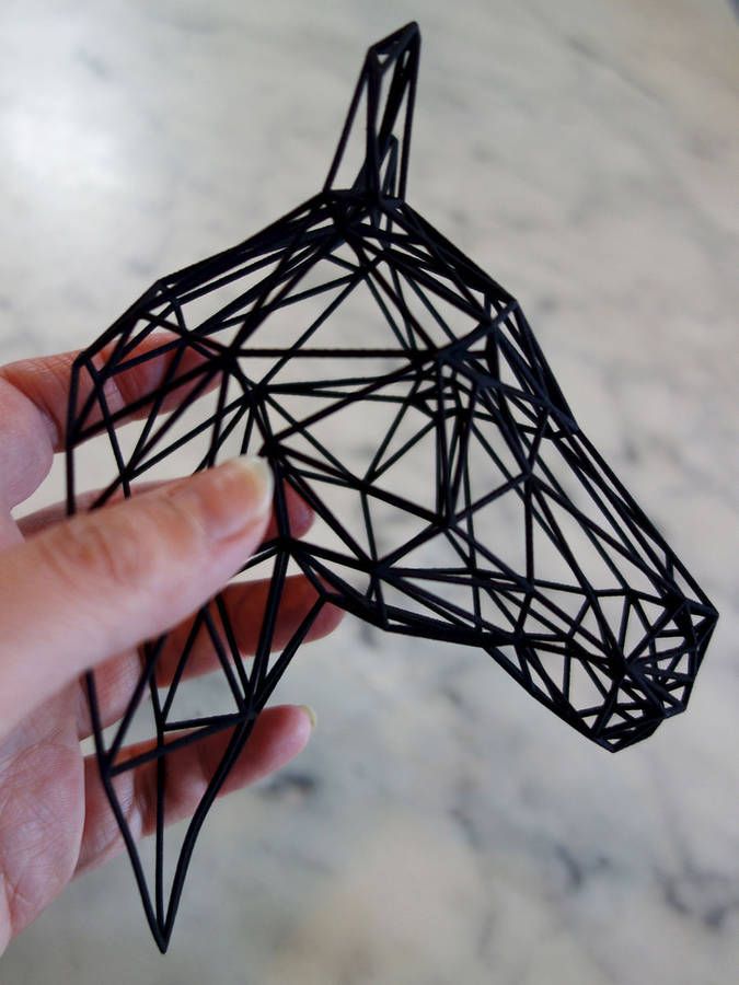 Figure 6: To prevent collisions, (a) the print head can neither print next to already printed material, (b) nor descend more steeply than the threshold angle. These constraints still allow for several different approaches to convert a 3D model into a printable wireframe. Figure 7c shows another approach that leaves out the contour and uses a different pattern. While this approach respects the constraints stated above, it leads to less sturdier results. Figure 7: (a) Solid sphere. (b,c) Different ways of printing the sphere as a wireframe. Extending WirePrint In this section, we present extensions to our basic approach that allow us to handle additional scenarios. Additional detail by mixing in layer-wise printing WirePrint also allows designers to preview detailed parts using layer-wise printing while the rest is printed as a wireframe. For instance, in the case of the bunny head shown in Figure 8, the designer wants to preview the details of the face, such as the eyes and the nose, in the context of the face.
 This hybrid mix of both techniques allows for quick iteration while ensuring enough detail in those regions where it is required. To mark a region for layer-wise printing, the user simply uses the fill-brush in the WirePrint software and brushes the sections of the zigzag pattern that should be printed in additional detail. Figure 8: Mixing in layer-wise printing: (a) after checking the shape of the bunny head, the designer decides to (b) print additional detail in the next iteration. As shown in Figure 9, WirePrint prints hybrid models slice-by-slice. (a) It starts each slice by printing the contour, which is shared between the traditionally printed part and the wireframe printed part. It then prints the wireframe zigzag, while it is still able to place the slanted starting point. It finally prints the layer-wise printing part. (b) Afterwards, WirePrint continues with the procedure on the next slice. Figure 9: Order of printing edges for hybrid printing when wireframe and traditional printing are mixed.
 Objects with filled surfaces Some 3D models, including the bottle mentioned in the previous section, require closed surfaces. To close the surface, we dip the wireframe print into glue (see Figure 10). An added advantage of this approach is that it strengthens the model. Figure 10: Filling surfaces, here the walls of the bottle, by dipping the wireframe into glue (e.g. Mod Podge). Contribution, Benefits, and Limitations In this paper, we make three contributions. (1) We propose 3D printing wireframe representations of 3D models as an approach to faster iteration in the early stages of 3D design. (2) To maximize the speed-up, we print edges directly into 3D space, i.e., we instruct 3D printers to extrude filament not layer-by-layer, but along actual strokes in 3D-space. This approach allows us to achieve speed-ups of up to a factor of 10 compared to traditional layer-wise 3D printing (factors range from 2.5-10 depending on the model geometry).
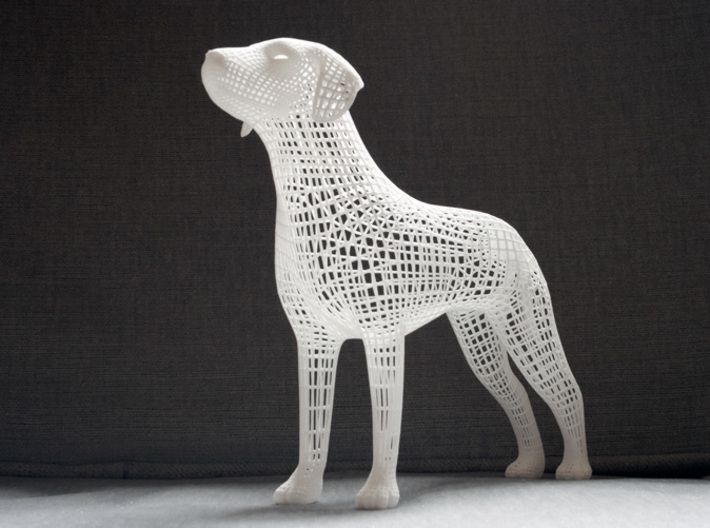
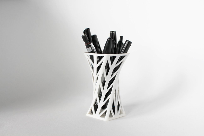
 Figure 11: A selection of objects we have 3D printed using WirePrint. Given that only a fraction of material is extruded, our approach is also substantially cheaper, making it even more affordable for designers to iterate. (3) To make our approach applicable to a wide range of users, we demonstrate how to create wireframe previews with existing FDM 3D printers—users only need to install the WirePrint software. On the flipside, our approach is less suitable for the later stages of design, i.e., stages where users want to test the actual physical strength of their design, when details and textures matter, or if objects have to perform mechanical functions (e.g., a screw). In addition, WirePrint is limited to model geometries that take the print head constraints into account (see section How WirePrint works). WirePrint is especially designed to speed up fused deposition modeling (FDM) 3D printing (e.g. PrintrBot, Kossel mini, MakerBot).
 It does not speed up 3D printers that print layers as raster images (e.g. Polyjet, ZCorp) and only small speed ups might be achieved on selective laser sintering or stereo lithography approaches. The Mechanical Aspects Behind WirePrint The main objective of the mechanical design behind WirePrint is to maximize the stability of the produced objects while minimizing printing time. Delta Printer All of the wireframe models shown in this paper were printed on Kossel mini 3D printer (Figure 12), i.e., a small volume printer that actuates the print head using six vertically actuated arms (a so-called delta design). Figure 12: We use a Kossel mini delta printer. For additional speed we improved the fan cooling system. WirePrint is particularly fast on the delta design, because delta printers allow the print head to move up and down quickly. 3D printers following the more traditional Cartesian design tend to be slower along the vertical axis since layer-wise printing does not require high speeds in this direction.
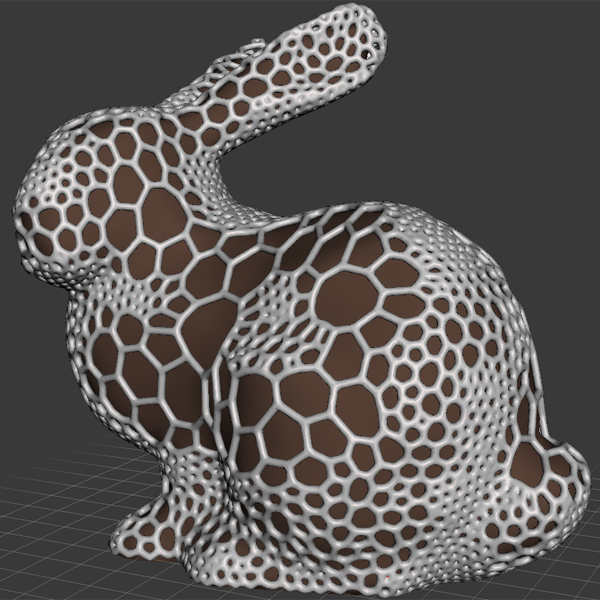 However, since the axis speed in the z-direction is simply a design decision of the manufacturers, WirePrint can be made equally fast on Cartesian printers with the proper hardware design, i.e. by changing both the movement/turn ratio and the stepper motor speed in the z- direction. Optimizing the filament for fast wireframe printing Since WirePrint requires frequent transitions between compliant and solid, we found materials that have a quick transition time to work best. From the two currently most common 3D printing materials PLA and ABS, the latter one works best. The reason is that ABS has a smaller temperature range, in which it changes its viscosity from compliant to solid (230–250° C) than PLA (180–250° C). Extrusion thickness A larger opening in the extrusion nozzle leads to thicker and thus sturdier edges and thus to sturdier objects. On the flipside, thicker edges require more time to cool down, which slows down the printing process.
 For our purposes, we found a 0.7mm extrusion nozzle to lead to the best results, i.e. sturdy and fast to print. Cooling We attached two air jets that are controlled by a solenoid valve to our print head (Figure 12). WirePrint controls the airflow by opening and closing the valve using g-code (command M42). The additional cooling causes the filament to solidify faster after extrusion, which allows WirePrint to move on even faster. In cases where WirePrint needs the filament to stick to another part of the model, it turns the cooling off. In cases where no additional cooling can be added to the 3D printer, WirePrint can either make use of the weaker built-in fan or can add an additional pause to wait for material to solidify. Support structures One interesting aspect of our technique is that WirePrint requires less support material than regular layer-wise 3D printing because it can print overhangs of up to 90°. An example of a small 90° overhang can be seen in Figure 1c at the bottom part of the model (the maximum length we tested was 6.
 5cm length). WirePrint can print these overhangs because the string of extruded material is put under tension until it is completely sturdy. Yet other geometry, such as a human figure extending the arms downwards, can only be printed with support. As in the layer-wise FDM approach, the need of support will reduce the overall print speed. However, one can think of using WirePrint to print support structures—again saving time compared to the currently existing approach. Implementation To help readers replicate our results, we use the following two sections to explain the details of our software imple- mentation, as well as the mechanical aspects behind our approach. The WirePrint system Our system WirePrint loads 3D models in STL format and generates custom g-code (i.e., the instruction language used by 3D printers). The user can then export the g-code and load it into the standard 3D printing software for printing (we use Repetier Host [16]).
 The custom g-code moves the print head along the desired path and controls how much material is extruded at which points. WirePrint is written in CoffeeScript and uses the construc- tive solid geometry library for its geometry operations. #1 Slicing the model After loading the 3D model, WirePrint slices the model into a set of slices. The locations of the slices is determined by (1)important features on the model geometry, and (2) the minimum and maximum height of the zigzag between two subsequent slices (we use a 0.7mm extrusion nozzle, which leads to 1.4mm minimal height, and our print head is 6mm high which leads to 6mm maximum height). To generate a slice, WirePrint cuts the 3D model against a horizontal slice (width and length of the object’s bounding box) at a specific height using a Boolean intersect operation. #2 Extracting the contour of a slice From each slice, WirePrint extracts the top contour by converting it to a high-resolution bitmap and then applying OpenCV’s findContour algorithm.
 If there are multiple contours on one slice, OpenCV’s findContour algorithm also returns their relationship to each other, i.e. whether they are located next to each other or contained in each other. We use this information to determine the printing order. #3 Generating the zigzag pattern When generating the zigzag pattern, WirePrint maximizes the object’s physical stability by aligning all vertical lines across slices. Simply using the points from the slice below does not work, because subsequent slices might: (1) have a different contour length, which can lead to insufficient space between two subsequent points (print head collision), and (2) slices might have different heights, which can lead to invalid printing angles. We therefore use a mixed approach: First we calculate the optimal even spacing of points for each contour. Then we calculate the minimum distance from a point on the bottom slice to the top slice. We then use the average of both, which leads to good stability and a comparably homogeneous spacing.
 In the case that two vertical lines are still too close to each other, we ignore one of them. #4 Compensating for mechanical aspects After generating the wireframe according to the model geometry, WirePrint applies all geometrical modifications that are required due to the mechanical properties of filament and print head e.g. removing the last diagonal edge of the zigzag from the list of edges to avoid print head collision. #5 Exporting g-code In the last step, WirePrint converts the geometry information into g-code. For this, it traverses the list of edges (all contours and zigzag patterns) to export them in the right order for printing. It uses the start and end point coordinates of each edge to generate the movement commands for the print head and the length of the edge to determine how much extrusion is required (e.g. G1 X10 Y 10 Z10 E5 means: move to those coordinates and extrude 5 units of filament on the way). Our g-code exporter also generates the commands for turning the fan on and off to properly cool the wireframe edges.
 The g-code exporter writes these g-code commands into a .gcode file that the user can then execute on the 3D printer. #6 Detecting geometry splits in the geometry In cases where a slice has a single contour and its subsequent slice has two (and vice versa), we print them on top of each other without the intermediate zigzag pattern. We use this particular approach to ensure that the zigzag of each new slice has filament printed underneath it. #7 Combining with layer-wise printing For mixing in layer-wise 3D printing, WirePrint generates additional slices between two subsequent wireframe slices. The number of additional slices depends on the printing resolution (e.g. if two wireframe slices are 3.5mm apart and the extrusion nozzle is 0.7mm, WirePrint will generate 3.5mm/0.7mm = 5 additional layers). After generating the slices and extracting their contours, WirePrint analyzes which part has been selected for layer-wise printing. It then cuts the contours at the start and end point of the selected part.
 The remaining part is filled with the zigzag pattern. Experimentation to Optimize Printing Speed To create accurate and sturdy wireframes, WirePrint needs to take into account the edge deformation that appears when filament is not yet solidified (see Figure 13). Figure 13: Deformation problem when edges are not yet solidified. We identified three potential approaches to improve the quality of a WirePrint: 1. WirePrint reduces the overall speed with which the print head moves, allowing the filament to solidify as it’s being printed; 2. WirePrint moves the print head quickly, but pauses at the end of each vertical edge to let the edge solidify; 3.WirePrint prints full speed, but anticipates the deformation by extending the vertical movement of the print head (see Figure 14). Through experimentation, we discovered that the fastest way to print is to add a delay at the end of each floating edge. Although a pause at the end of each vertical edge initially seemed unattractive, it lead to the most accurate results because the edges solidify under tension.
 Anticipating the deformation during printing was attractive at first, but the extra traveling time of the print head quickly undermined the benefit of a faster printing speed, and in general the results where less appealing. Figure 14: Approach #3: compensating for material transition time. To better understand the interactions between speed and delay, we performed a series of test prints with a sphere (radius=3.9cm), which are shown in Figure 15. During our tests, we found that the best solution is to move with the maximum extrusion speed of the printer (30mm/s) combined with a 1s pause at the end of each vertical line. Figure 15: Print head speed/pause trade-off. Validation The main strength of WirePrint is that it produces a substantial speed-up of up to a factor of 10. To validate that this speed-up results from extruding filament into 3D space, we also implemented wireframe printing based on traditional layer-wise 3D printing as a control condition.
 We implemented layer-wise wireframe printing as follows: (1) print only the edges of a model, and (2) minimize the use of support material, as this adds to the printing volume (support material is required for all overhangs larger than 45 degree). We wrote a piece of software that converts a 3D model into a wireframe mesh and that adds additional 45 degree edges as support structures where needed. For instance, a cube processed with our software has support edges for the horizontal edges at the top (see Figure 16b). We compared the three conditions using the simple example of a 28mm cube. Figure 16 shows the printing times for (a) traditional layer-wise 3D printing (solid with 10% infill), (b) traditional layer-wise 3D printing (wireframe, edges have 10% infill), and (c) WirePrint. Figure 16: Printing times: (a) layer-wise 3D printing with 10% infill, (b) layer-wise 3D printing of a wireframe (reduced volume, 10% infill), (c) WirePrint. Although printing a wireframe layer-wise substantially reduces the volume, there is only modest improvement in printing time (factor 2x, 24:59 minutes for layer-wise solid printing vs.
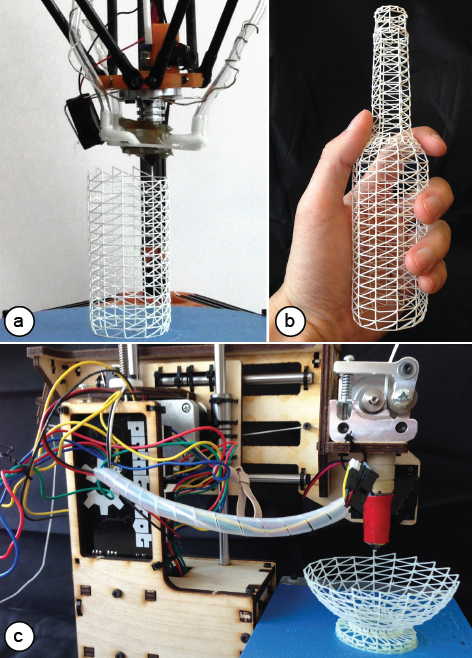 10:23 minutes for layer-wise wireframe printing). The layer-wise printed wireframe was also substantially slower than the model generated by WirePrint (10:23 minutes for layer-wise printing vs. 2:26 minutes for WirePrint). Surprisingly, the layer-wise printed wireframe model only provided a 2x speed up compared to the regular printed model with faces and more infill material. We found that the main reason for this is that the path for the print head remains almost the same. Figure 17 illustrates this: Since the material is printed layer-wise, the print head still has to traverse the entire cube outline as it moves from corner to corner, bottom-up. Figure 17: The print path simulation (gray lines) shows that for layer-wise printing, the print head has to move along the entire cube outline. Our quick validation shows that the performance benefits of WirePrint indeed result from implementing the ability to extrude strokes in 3D space, rather than printing them layer-wise.
 Conclusion In this paper, we proposed a novel approach to 3D prototyping, i.e. to print wireframe representations instead of a filled model and to extrude filament directly into 3D space instead of printing layer-wise. Our validation shows that in combination, these two approaches indeed lead to a substantial speed up of up to a factor of 10 and thus allow designers to iterate more often. For future work, we plan to explore how fast 3D printing allows for novel types of interfaces that close the feedback loop between digital editing and physical fabrication.
Wireframe best STL files for 3D printer・Cults
Wireframe Rhombic Dodecahedron
€1.92
Biomimicry Pen Holder 2.0
€6.25
Biomimicry Pen Holder 1
€6.26
Moebius 3D double interlocked wireframe
Free
Gear set clips for Tiger Moth RC model plane
Free
WIREFRAME DEER WALL THROPHY
€4.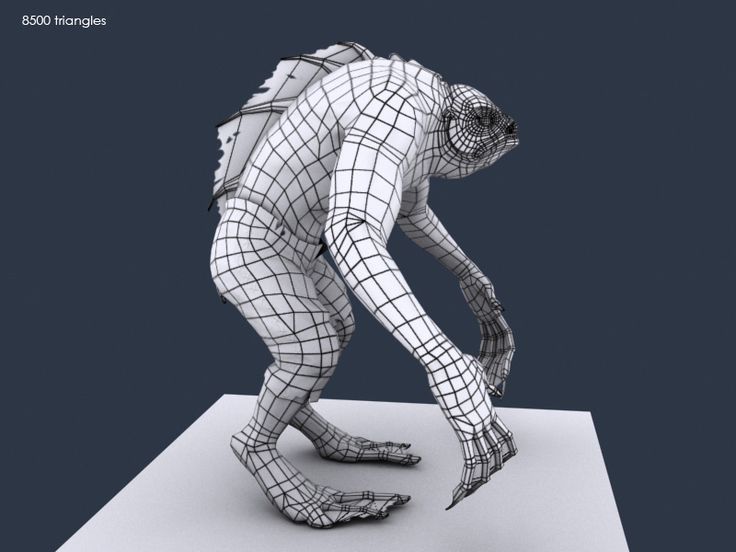 90
90
Wednesday Addams bust WIREFRAME VORONOI WIREMESH MESH
€2
Venom bust WIREFRAME VORONOI WIREMESH MESH
€2
TOTORO WIREFRAME VORONOI WIREMESH MESH
€2
Terminator bust WIREFRAME VORONOI WIREMESH MESH
€2
Theodore Roosevelt bust WIREFRAME VORONOI WIREMESH MESH
€2
SMALL TOTORO WIREFRAME VORONOI WIREMESH MESH
€2
Skull WIREFRAME VORONOI WIREMESH MESH
€2
ScoobyDoo bust WIREFRAME VORONOI WIREMESH MESH
€2
Ra bust WIREFRAME VORONOI WIREMESH MESH
€2
Nemesis Residual Evil bust WIREFRAME VORONOI WIREMESH MESH
€2
Moai bust WIREFRAME VORONOI WIREMESH MESH
€2
Kratos bust WIREFRAME VORONOI WIREMESH MESH
€2
Godzilla bust WIREFRAME VORONOI WIREMESH MESH
€2
Freddie Mercury bust WIREFRAME VORONOI WIREMESH MESH
€2
Dobby bust Harry Potter WIREFRAME VORONOI WIREMESH MESH
€2
Deadpool bust WIREFRAME VORONOI WIREMESH MESH
€2
Pokemon Bulbasaur WIREFRAME VORONOI WIREMESH MESH
€2
BIG TOTORO WIREFRAME VORONOI WIREMESH MESH
€2
Anubis bust WIREFRAME VORONOI WIREMESH MESH
€2
Medusa bust WIREFRAME VORONOI WIREMESH MESH
€1.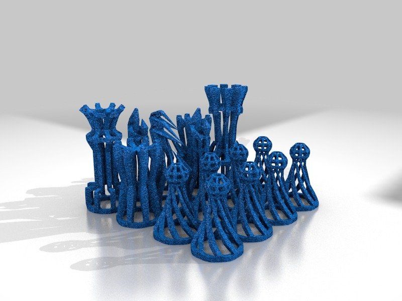 50
50
Heracles bust WIREFRAME VORONOI WIREMESH MESH
€1.50
Alexander the Great bust WIREFRAME VORONOI WIREMESH MESH
€1.50
Ajax the Great bust WIREFRAME VORONOI WIREMESH MESH
€1.50
Nefertiti WIREFRAME VORONOI WIREMESH MESH
€1.50
Alduin Elder Scrolls WIREFRAME VORONOI WIREMESH MESH
€1.50
Marcus Aurelius Bust WIREFRAME VORONOI WIREMESH MESH
€1
Nikola Tesla BUST WIREFRAME VORONOI WIREMESH MESH
€1
NIKOLA TESLA BUST WIREFRAME VORONOI WIREMESH MESH
€1
Wireframe pyramid
€2.88
Wireframe dodecahedron
€5.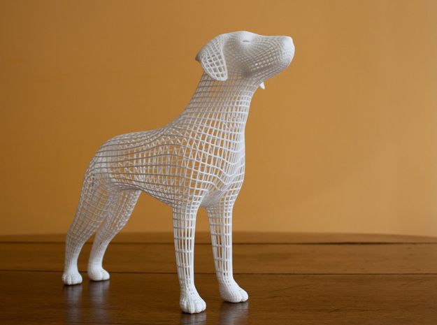 76
76
Wireframe Sphere 003
€2
Wireframe Sphere 002
€2
Wireframe Sphere 001
€2
Pokeball - Pokeball - Pokemon Voxel
Free
Open work cross diamond engraving band US sizes 5to9 3D print model
€5.76
LOWPOLY AND WIREFRAME FLAMINGO
€2.90
Hollow Dodecahedron
Free
WIREFRAME COLLECTION BUNDLE (9 DESIGNS)
€19
mathematical cube
Free
Pokemon Kit LowPoly - Wireframe
€1.24
RHINO WIREFRAME 3D SCULPTURE
€2.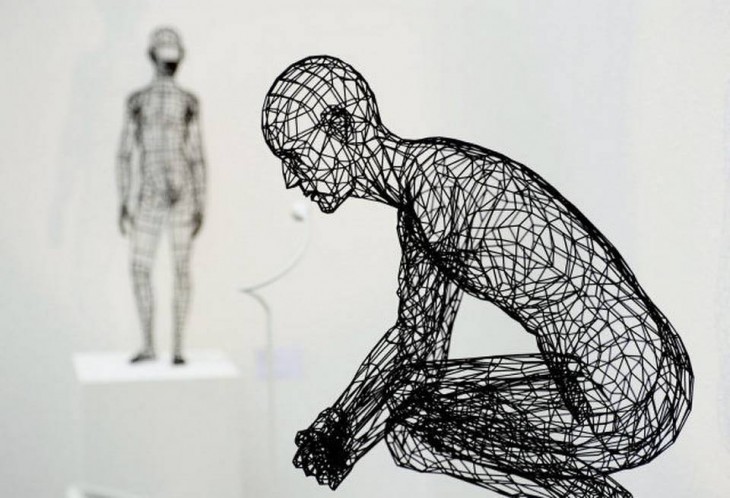 90
90
FUCK YOU WIREFRAME
€1
Free STL file Frame Modular Structure・Design for Download and 3D Printing・Cults
Low polished Ionic, Doric, Corinthian columns
Free
Lock pen holder
Free
Spearhead M1
Free
Tree without support
Free of charge
24-piece nail set
Free
Mosque
Free
Cyberpunk motorcycle
Free
Geological hammer
Free
Best 3D Printer Files in Home Category
Tom Dixon - Beat Pendant Lights
9. 46 €
46 €
7 Vases to sell
1.83 €
Spiral Sphere Ornament - Customizer enabled
Free
Knife Handles cnc
Free
Baby Groot Extra Cute Dancing
€4.99
H.A.V.O.C. Vase Collection
2,50 €
Xmas 2021 Bauble - Spikes
Free
Ornaments
Free
Bestsellers in the Home category
Venus and Aphrodite
3.60 €
Notepad
2.60 €
Christmas reindeer Rudolf - Crex
3,20 €
Key hanger with pokemon balls (Pikachu, Gengar)
2. 04 €
04 €
Harry Potter Christmas ornaments
2.76 €
Egg cracker
1.03 €
Ornamented tea holder
€2.85 -35% 1.85 €
Pencil with dinosaur gluttony
1.86 €
Wall shelf "Oyster mushroom"
2,40 €
Die Hard Advent Calendar
6.19 €
Modular storage box system with quick print
5.82 €
Snowman - Crex
3.20 €
Another quick-change paper towel holder
1 €
Candlestick - Arbre de vie
1. 20 €
20 €
Wall shelf "Tinder Fungus"
2.40 €
Another quick-change toilet roll holder
1 €
Do you want to support Cults?
Do you like Cults and want to help us continue our journey on our own ? Please note that we are a small team of 3 people , so supporting us in keeping and creating future developments is easy. Here are 4 solutions available to everyone:
-
ADVERTISING: Disable the AdBlock banner blocker and click on our banner ads.
-
AFFILIATION: Shop online with our affiliate links here Amazon.
-
DONATIONS: If you want, you can donate via PayPal here.
-
* INVITE FRIENDS: * Invite your friends, discover the platform and great 3D files shared by the community!
Construction 3D printing in anticipation of a breakthrough / Sudo Null IT News
3D printing technology originated in the 80s of the 20th century, but construction 3D printing appeared much later.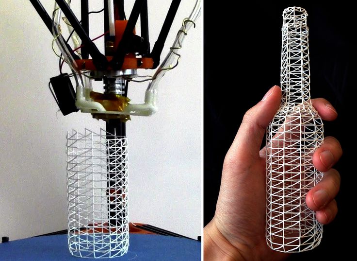 The first construction projects using this technology appeared only in 2014. We are talking, first of all, about the so-called small architectural forms (benches, flower beds, fences). They never even dreamed about building houses. But already in 2015, the Russian startup Apis Cor made a splash - it printed a whole house in the Moscow region. Since then, news about new 3D printed houses has periodically appeared. However, despite the fact that the technology proved to be very promising in terms of the speed of construction of housing and the reduction in the cost of construction, no mass implementation followed.
Construction is the world's number one market. And, if many technological innovations are being introduced in the field of high-rise construction, then little has changed in the field of low-rise construction over the past decades. The last 30 years have seen the availability of the Internet, mobile phones, mobile internet, robotics taken to a new level, etc., but when you get to a house construction site, you are unlikely to find many technological innovations.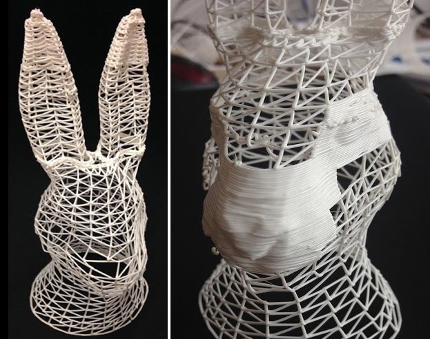 Automation is practically non-existent, and manual labor prevails. 2020 was a test of strength for the whole world, and also led to the highest level of inflation, which, first of all, hit the construction market, there was a dramatic change in prices for metals, cement, wood and much more.
This Internet meme shows what happened to the cost of building materials in just a year. And the process is still going on. At the same time, there is a serious rise in the cost of labor, and there is an acute shortage of it. All this leads to a sharp rise in the cost of building houses. No matter how strange it may sound, statistics show that the growth of automation does not occur when everything is fine, but precisely in crisis situations, during increased competition, reduced demand and the need to urgently look for new technologies to increase production efficiency. So it happened this time, and after some stagnation, construction 3D printing received a new impetus for development.
Preparing to write an article, I turned to the founder of Arkon - Boris Kozlov y. Arkon was established in 2020 and is engaged in the production of construction 3D printers, both a workshop type for creating prefabs (prefabricated houses) and a portal one capable of printing a two-story house. I asked Boris the key, in my opinion, question:
- Construction 3D printing appeared in 2014, but no mass introduction of this technology followed in 7-8 years. Why do you think this happened, and why is there a surge of new projects right now?
- It seems to me that the reason is the snowball effect. The technology had to mature, grow from a hypothesis to a pilot implementation, and finally to commercialization and scaling (what is happening now). In addition, it should be borne in mind that construction is one of the most conservative industries, where, unlike even aviation and the automotive industry, there is still an extremely low introduction of digital solutions and automation in the field of the production process itself - the construction itself.
The issue of regulation and certification also plays an important role - this process is long and creates an additional lag.
2014-2016 the first samples of building 3D printers and prototypes of printed buildings appeared. The concepts of various form factors of construction 3D printers and types of printing materials were tested.
In 2017-2018 in the world, the first notable investments were made in a number of construction 3D printing start-ups. Further, by 2020, these investments "rolled" in the form of reaching a certain level of technology maturity - the first commercial products (3D printers and houses) appeared.
Finally, in 2020-2022 it became clear that the hypotheses of the effectiveness of construction 3D printing were justified (cheaper, faster, more environmentally friendly), and large investments began in the industry. A striking example is the investment of GE (the French division of General Electric) in the Danish COBOD or the achievement of a capitalization of $ 2 billion by the American company ICON.
In 2022-2023 over 1,000 buildings will be printed worldwide already, scaling from single buildings/pilot projects to entire villages and major infrastructure/reinforced concrete implementations. In addition, in a number of countries, by now, a regulatory framework has been created or is being actively created for the introduction of additive technologies in the construction industry.
Thus, I believe that the specified time period is a fairly natural cycle of technology development, which is likely to experience exponential growth in the next decade.
According to ResearchAndMarket report, the global construction 3D printing market is valued at USD 354.3 million in 2022 and is projected to reach USD 11068.1 million by 2027, an increase of 99.04%.
Various market processes affect the prices and behavior of participants in the global 3D construction printing market. They create price signals that are the result of changes in the demand and supply curves for a product or service. They can be associated with both macroeconomic and microeconomic factors. Even human emotions can also drive decisions, influence the market, and create price signals.
Now let's take a quick look at what is the construction 3D printer. Without delving too deeply into the technology, we can say that construction 3D printers are very similar to classic FDM/FFF printers that print with plastic, but instead of plastic, the material here is a cement mixture, which is fed directly into the nozzle and forms an object by layer-by-layer overlay. Printers are also portal, on the basis of a flying boom, with a robotic arm.
Shown on the left is a boom-based construction printer. The figure on the right is a gantry construction 3D printer
In the figure above, a construction 3D printer in the form of a robot arm installed on a mobile platform.
Everything changed completely when, in the summer of 2021, the American company ICON, which was trying to introduce 3D printing into the construction of various auxiliary facilities, signed a contract with one of the largest American developers, Lennar, to build a village of 100 houses in Texas and immediately became a unicorn , having received 200 million dollars of investments from several investment funds.
At the same time, the Danish company COBOD, created by the world's largest construction formwork company PERRI, began selling its gantry 3D construction printers, as well as participating in construction projects around the world. In the photo below, a modern two-story house built in Germany and a school building in Malawi, built in record time with a minimal budget.
There is little that unites developed, developing and poor countries, everywhere their problems and tasks, but The lack of affordable housing is a global agenda . If in poor countries there is an acute problem with the increase in the number of homeless people due to a lack of housing, as such, then in developing countries it is necessary to dramatically accelerate the number of new housing being built to meet the needs of a growing population. In developed countries, the problem is primarily in the cost of housing, which has risen in price to such an extent that it has become practically inaccessible to young people. And with the simultaneous increase in life expectancy in these countries, this problem is only getting worse.
At the same time, the trend towards “green agenda ”, CO2 emission reduction, building with more environmentally friendly materials, etc. is developing. But, unfortunately, so far the construction industry is the absolute leader in CO2 emissions, as well as in the amount of garbage that each construction site leaves behind. This is not to say that construction 3D printing solves all these problems, but at least it is moving in the right direction. Let's look at this with a few illustrative examples.
3D printed walls. Today, when we talk about 3D printing houses, we are talking about printing walls. Everything else (foundation, windows, doors, ceilings and roof) is done in the traditional way. 3D printed walls are built as fixed formwork, which significantly saves the amount of cement used , and this, in turn, reduces the cost of construction and reduces the environmental impact of cement production. In addition, with this method of construction, no additional waste is produced, the strength of the structure does not suffer. It can be reinforced, as shown in the photo on the left, and engineering communications can be immediately laid, as shown in the photo on the right, which also affects the final speed of the construction of the object. At the same time, the total weight of the structure is reduced, the remaining cavities can be filled with lightweight foam concrete, insulation, straw or any other available material. Such a lightweight design can use a lighter foundation. The construction method itself is more economical in terms of material, and therefore environmentally friendly.
eco-concrete with the addition of polymers is being actively developed, the production of which reduces CO2 emissions from 30% to 100%. The Apis Cor company mentioned at the beginning of the article, which built a house in the suburbs in 2015, is now based in hot Florida, plans to start using this material in its projects.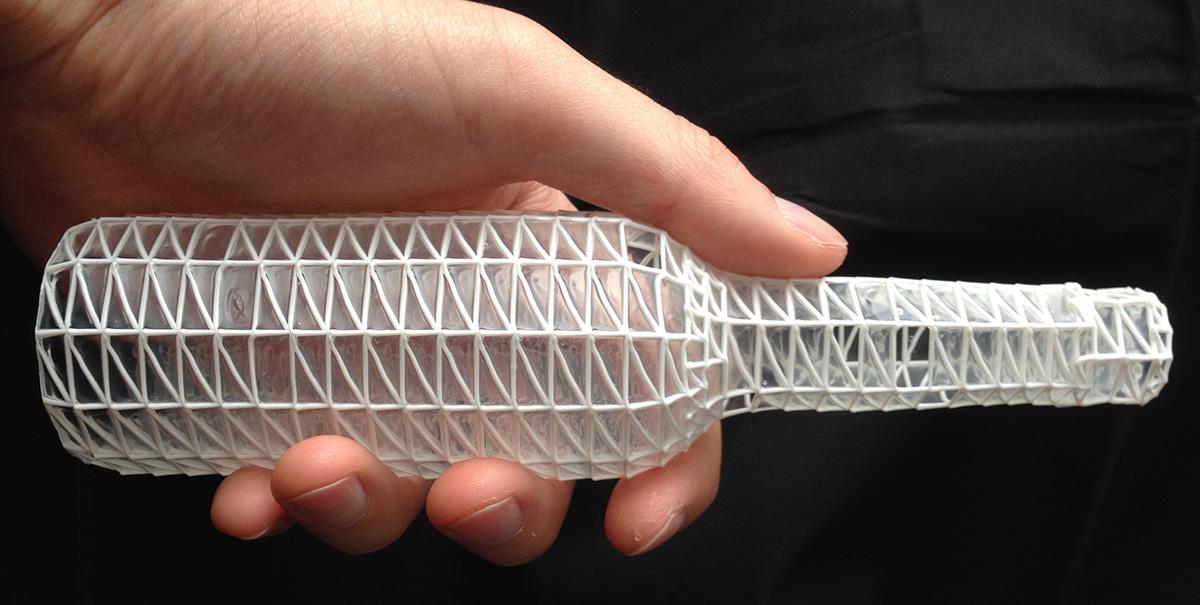
Another start-up from Russia, Mighty Buildings, headquartered in California, initially opted for a polymer with the addition of mineral chips. And while the company doesn't build entire homes, it only makes wall panels, it has won numerous design awards, as well as a $400 million valuation in several investment rounds.
As a result, with a rough calculation, we can say that the total savings on the construction of walls can reach 30%, and the total cost of the house can be reduced by 10%. This is true for houses designed for conventional construction. And if you initially design with 3D printing, you can improve this ratio by optimizing the laying of communications, the ability to immediately print interior walls, bookmark niches for bathrooms, fireplaces, built-in wardrobes and kitchens, as was done in the house built by COBOD in Germany.
"There are spots on the sun." Despite all the advantages of building 3D printing, has several significant disadvantages . The main one is layering, which cannot be avoided at the current level of technology development.
The photo above shows the layering of the 3D printed walls.
This task can be worked in several directions:
-
Ribbed walls can be plastered, painted and played with as a design element. That's how ICON does it in the US, for example their latest project House Zero is done that way and has won a number of design awards.
-
Use special "shutters" on the print head that allow smooth layers, as COBOD and other manufacturers do. The photo below shows that this does not ensure the complete absence of layering.
-
Fully sand the surface to get the usual smooth wall for plastering, painting, wallpapering or other finishing. It is possible, but it will require huge labor costs, which can reduce the overall efficiency of using 3D printing.
Pictured above is a 3D printed wall sanded smooth.
The second problem is the required temperature. Ideally, printing should take place at temperatures between +5C° and +30C°. Humidity is also important. Using additives, you can push these boundaries, but not indefinitely. At strong sub-zero temperatures, printing will be possible in the field only if the construction site is covered with a dome and the required temperature is reached inside with the help of heat guns. In conditions of intense heat, it is preferable to print at night. Another solution could be to print the wall panels in the shop and assemble them on site. Of course, each of these decisions will have a negative impact on the economic efficiency of the project.
Building 3D printing can be useful not only for the construction of houses . With its help, you can solve many other problems, and there its disadvantages will not matter. For example, the American concern GE uses COBOD printers to build towers for wind turbines in the shop. Ribbed surface and temperature restrictions in this case do not play any role.