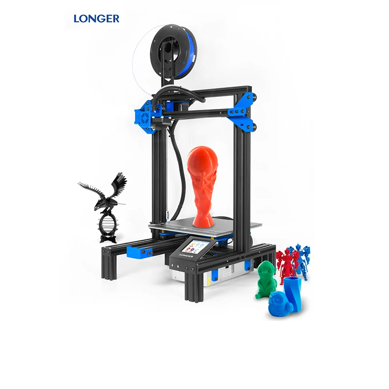
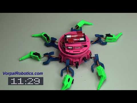
Hexapod 3d printer
3D Print Files for the Hexapod Robot
| TABLE OF CONTENTS Six Introduction and Setup 1. Getting Started with Six 3D Printing for Six Mobile App for Six 1. Using Six with Mobile App General CoursesSoftware 1. ARC for Windows PC Mobile Software 1. Create a Mobile App Linear Programming 1. Logical Programming 1. Programming Concepts (Variables, If/Else, Logic) Camera Input 1. Introduction to the EZ-B Camera Audio Input 1. Speech Recognition RGB Output 1. RGB Animations Positioning 1. Servo Control Navigation and Movement 1. Movement Panels Creative Applications 1. Customize Your EZ-Robot EZ-B v4 Robot Brain 1. EZ-B v4 Robot Brain Overview Robot Troubleshooting | 3D Print Files for SixWhile designing the plastic components for Six, we thought it would be great to open-source the STL files so anyone can 3D print replacement parts. Print files can be downloaded within the Design tool in ARC (formerly EZ-Builder). The Design tool also allows community members to upload their own parts to share with the world! What better use for your 3D printer than to make robot parts? PL-5700 - Lever Servo L-Bracket PL-5705 - Lever Servo U-Bracket Next Lesson >>> |
 Introduction to Servo Motors
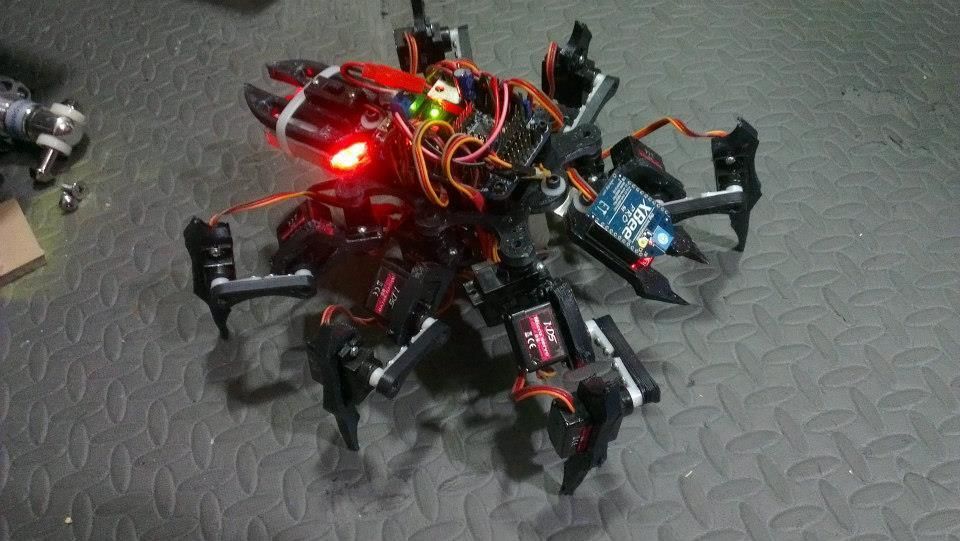
ZeroBug 3D printable hexapod — The MagPi magazine
“Zero is in charge of the input methods,” Maximilian explains. “It runs a custom web interface and an instance of Pygame. This makes it possible to control the robot using a mouse, keyboard, multitouch, or simply an Xbox gamepad... Instead of specialised robotics servos, this robot uses inexpensive micro servos. Inside its 3D-printed frame there is just enough room for Raspberry Pi, together with a custom PCB for the microcontroller and servo driver.”
The microcontroller is an STM32, which is an ARM-based system which controls the leg locomotion through 18 of the affordable servos.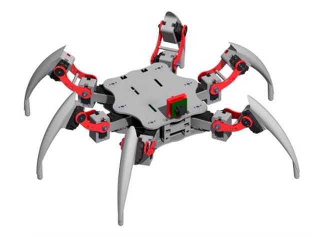
“All of these calculations run at 50Hz, enabling the hexapod to move smoothly and with high precision.”
Six degreesMaximilian was inspired by earlier videos of the Boston Dynamics robot experiments, and loved the idea of making robots with legs – starting with a quadrupedal creation of his own, before moving to six legs.
“It turned out to be really difficult to develop proper walking gaits, and the servos seemed to struggle with the weight of the robot,” he tells us. “The decision to go with four legs instead of six was mainly due to the cost of servo motors. However, six-legged robots have a big advantage: unlike quadrupeds, they can lift three of their legs while the remaining legs form a stable tripod. This eliminates the need for constant weight shifting and balancing.”
The decision to use Raspberry Pi was due to how easily you can connect Bluetooth controllers to it, making it more accessible than RC controllers. With this in mind, Maximilian started simulating his robot.
“With the simulation done, I went on to build the physical hexapod robot,” he says. “Since there are 18 servos needed for this hexapod, they define the total cost of the robot. I settled for some cheap Emax ES08A II micro servos which are quite powerful for their size. I only paid around €80 for the entire set of servos. When using proper smart servos for robotics, a single unit can cost this much.”
To drive the servos, 18 PWM outputs are needed. “I decided to use the STM32F103 as a microcontroller as it is Arduino-compatible, and I had already gathered some experience with my macro keyboard (magpi.cc/macrokeypad). To connect the microcontroller, PWM driver, and Raspberry Pi, I designed a custom PCB that plugs into the back of the GPIO header on Raspberry Pi. To save space, the connector only uses GPIO 1 though 10, which conveniently include 5 V, 3.3 V, ground, UART, and a couple extra I/O. Voltage regulators on the custom PCB enable the microcontroller and Raspberry Pi to be powered from the battery pack.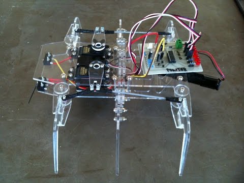 Both Zero W and the custom board are mounted between the servos, so that the USB port can be accessed from the outside.”
Maximilian claims that building a walking robot is not that hard; instead, making it look right while walking can be a challenge.
“Overall, I am really happy with how this project turned out,” Maximilian tells us. “I actually started working on a simulator in 2014 and shelved the whole project out of frustration, only to dig it up a few years later. Just at the start of last year it really clicked, and I got the motivation to go through with it.”
You can read a lot more about his development process on his Hackaday page, and he also has some ideas on how to improve it in the future.
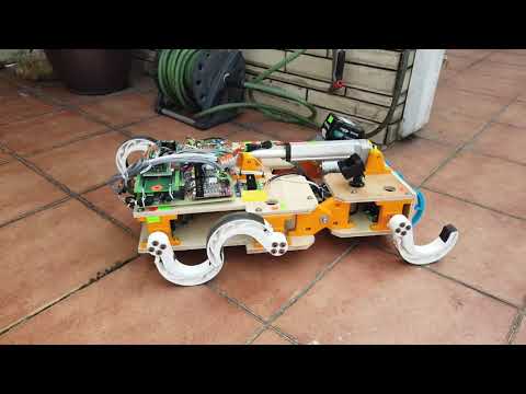
How we printed a hexapod and what came of it / Habr
Background
The hot summer was coming to an end, behind was a wonderful family vacation on the warm, gentle sea, and the outlines of gray working days were already showing through.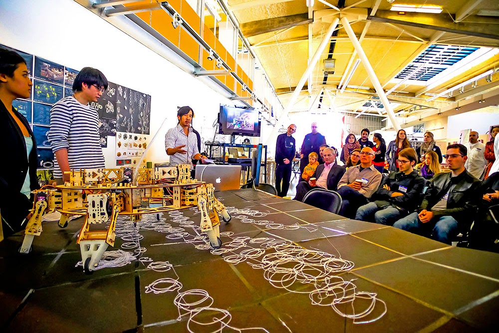 In order not to succumb to the autumn depression, it was necessary to urgently do something pleasant and useful, and this something did not take long: the eldest son had to prepare work for the school conference. The theme of the work has been hanging in the air for a long time. I follow with great interest the publications of the author of Neoprog “Developing a hexapod from scratch”. And it was his articles that inspired us to work in this direction. nine0005
Design
We chose MG-996R servos as the driving elements of the design. Of the declared characteristics, they have sufficiently high and power characteristics at a relatively low cost. The dimensions and design of this servo formed the basis for the further design of the robot, which we originally planned to make from plastic using 3D printing.
The first step was to build and test a working prototype of a single limb. nine0005
Having no experience in 3D modeling programs, we lightly decided to translate our paper sketches into a three-dimensional model using the built-in 3D builder editor in Windows 10. For all its simplicity, this editor has a fairly extensive arsenal and allows you to create fairly complex 3D models.
But the ease of use of this editor is also its weak point. The lack of control over the number of vertices in the model leads to the fact that after repeated shredding and gluing, a seemingly simple model begins to have with a huge inner world of the number of polygons and the editor begins to deal with some kind of internal recalculation of the model, allowing you only to contemplate your creation without the ability to edit something.
After a cursory analysis of the available editors, it was customary to use Blender because was free and was incomprehensible, and because I tried to study it several times and all attempts ended in fiasco. This time, having a specific goal paid off. The minimal but sufficient skill of working in the editor was subdued and we continued development. I would like to note that in the future we did not completely abandon work in the 3D builder. It is still much more convenient to perform some finishing actions with the model in it: make screw holes, cut out internal cavities of complex shape, and much more. nine0005
When designing the limb, we set the task of hiding the servos inside the body as much as possible. In general, this was successful, but the trains still had to be left outside in order to reduce the mechanical impact during flexion of the joints. At the same time, the design allows you to maintain the freedom of movement of the joints almost within the maximum range of 0 - 180 degrees. A bearing is provided in each joint to reduce friction and wear.
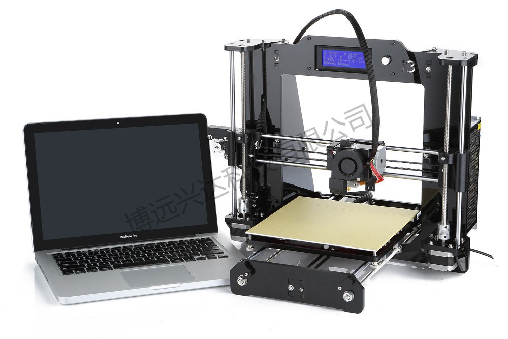
For printing, we used the Infintary 3D Printer, bought in China a couple of years ago. The process is quite slow, so it took more than one day to print the entire set of limbs. nine0005
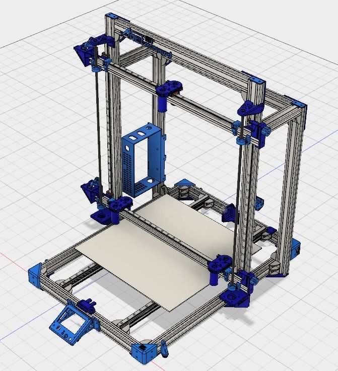
During this time, we sketched and built a 3D model of the frame to which the limbs should be attached. It also houses the servo drives of the shoulder joints.
Printing and assembly
After the printing was completed, we proceeded to the assembly of the limbs and the final assembly. In the disassembled version, a sort of constructor turned out:
When assembling, the main thing is not to forget to insert the bearings and servo rods. nine0005
An important point: at the time of assembly, all servos must be brought to the middle position. To calibrate the position of the shoulder joints, we printed and drew a special stencil.
As a result, we got a pretty nice six-legged platform, the revival of which was busy all our further leisure.
Electronic filling
By this time, the main set of electronic stuffing for the revival of the robot was compiled and completed. It includes ready-made components, namely:
- Main controller Arduino UNO + WiFi R3 ATmega328P + ESP8266
- Adjustable Regulators DC/DC Max 9A 300W - 6 pcs.
- High-current batteries HG2 18650 3000 mAh — 3 pcs.
- Charge controller BMS 3S 11.1 V 12.6 V 40A
- Multiservo Shield for 18 servos, controlled via I2C bus.
The use of off-the-shelf components had a negative impact on the size of the robot. Above the main frame, we had to build a second tier, in which we placed the stabilizers and the servo shield. nine0005
Arduino board and power system settled on the roof located in the third tier of the case. We also plan to add a pair of oled displays imitating eyes, a microphone, a camera and a distance sensor here.
At the moment, we have completed most of the planned work. "Geksa" (as we called our robot with the son) has been created and can be controlled via telnet or android devices through a specially written application.
Afterword
It is already deep winter in the yard, the days are getting longer and brighter. And that means spring and good mood are just around the corner. I would be glad if my first and hopefully not the last publication was interesting and useful to someone. The topic of the article was focused only on the description of the creation process, so the software stuffing and everything else was left behind the scenes. If you are interested, you can devote the following articles to this topic. Ready to answer all questions.
Thank you for your attention! nine0005
3d model for download
3d-model Hexapod
DOWNLOAD
-
Rating:
-
Difficulty:
Complex -
Weight:
96 KB -
Parts:
9 pcs.
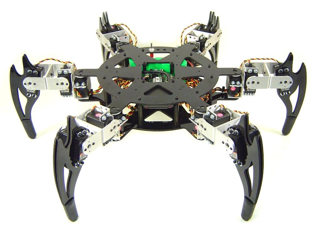
If you've already tried your hand at building and handling a four-legged spider, it's time to take things a step further. Now you can download free 3d model of a similar robot, but with 6 legs. It is also controlled by arduino. Let's say right away that it is better to use a shield to control and connect such a number of motors. The details of this robot are very simple, but there are many of them. If you have any problems during the 3d printing process, you can always contact our articles on 3D printing that will definitely help you cope with this task. nine0005
Having printed 3d models on a printer, it will become clear how to attach them, especially if you look at the picture. Therefore, it makes no sense to describe the assembly of this robot, you can do it yourself. But to discuss the difficulties that may arise during the assembly process, you need to discuss
Features:
First, let's start with the motors. This robot uses 12 sg 90 servo motors. Others can be used, but these are the most cost-effective ones that can be ordered on aliexpress. As in previous robots, we recommend that you first put all the motors at a certain angle (best 90) so that after assembly, some motors do not end up in a rotational dead zone.