Heat set inserts for 3d printing
Using Heat Set Inserts
Learn Blog
Threaded components, holes, and bolted connections are integral to a wide variety of engineering parts that you work with every day, so being able to add effective threads to 3D printed parts is important. Tapped or printed plastic threads are easy to overload and strip out, while metal threads are stronger and wear resistant, providing a better connection over time. Metal threaded inserts provide a surefire fastening method for plastic parts. Threaded inserts are commonly brass with a pre-formed thread within them. They resist pull-out and torque-out loads with knurled external surface features designed to interface with the bulk material of the larger part. There are a few different types of threaded inserts depending on the materials and applications you are working with. For 3D printing, we recommend heat-set inserts.
Heat-set inserts are perfect for thermoplastics in 3D printing because during installation the thermoplastic melts and reflows around the insert. This makes the plastic surrounding the insert locally stronger, and establishes a secure bond between the metal insert and the thermoplastic. This in turn ensures a much stronger pull-out and torque-out rating of the resulting thread as compared to other types of inserts.
U.S. Army Case Study
Read our newest customer success story about a major training base for the U.S. Army.
Designing for and installing heat-set inserts
Designing for and installing heat-set threaded inserts for lower volume applications requires only a few inexpensive tools. Inserts require a tapered cavity of a specific size for installation, so you’ll need to find the recommended cavity dimensions from your insert vendor.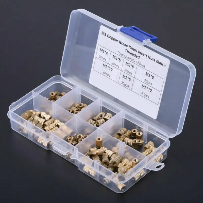 During installation, the insert will melt and displace some plastic from the surrounding part as it descends, so the taper allows the molten plastic to fully envelop the knurled surface of the insert. Follow the steps below to design for and install a heat-set insert.
What you'll need
- 3D printed part with appropriate holes for threaded inserts
- Desired threaded inserts
- Soldering iron
- (Optional) Threaded insert installation tip for soldering iron
1. Select your bolt size and corresponding heat-set insert
Select what hardware you’ll use to fasten the part during the design process. Insert size is partially driven by the thickness of the material surrounding it. If you have less than 2 mm (0.078”) of material around and below your insert, consider dropping to a smaller size. Check the insert vendor’s recommendations for insert cavity size to make sure it can fit in your part. In this example, we’ll be using an M3 insert with the following cavity specifications:
Hole depth (D): 3. 8 mm
8 mm
Major diameter (A): 5.31 mm
Minor diameter (B): 5.1 mm
Read our 3D Printer Buyer's Guide for Manufacturing
2. Sketch the starting point for your holes
Use the sketch tool or similar tool in your CAD program to pinpoint where you want your holes to start.
3. Use the Hole tool to create a counterbored hole
Using the Hole tool (or similar depending upon your CAD program), create a counterbored hole on the specified points with the recommended hole depth and major diameter (A) of the taper for the insert. You can extend the hole itself past the base of the counterbore if you need a relief hole for screw clearance. Here the diameter of the counterbore is 5.31 mm, with a depth of 3.8 mm.
4. Chamfer the inner bore edge
Apply a Distance-Distance chamfer to the lower outside edge of the counterbored hole with the counterbore height as the distance going up the counterbore, and the value that will achieve “B” as your minor taper diameter as the other, which equates to (A-B)/2 for our needs.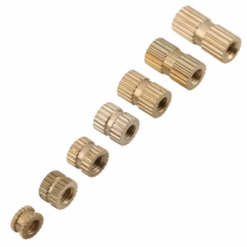 Depending on what format your cavity dimensions are provided, you may need to alter the way you perform this operation.
Check out our Composites Design Guide
5. Print your part
Once your design is complete, print out your part!
6. Heat up your soldering iron
Plug your soldering iron in, turn it on, and wait for it to get up to temperature. A good iron operating temperature is 650-750 F (343-399 C).
7. Press in each insert with the soldering iron
Place each insert above its cavity, making sure it is straight and centered.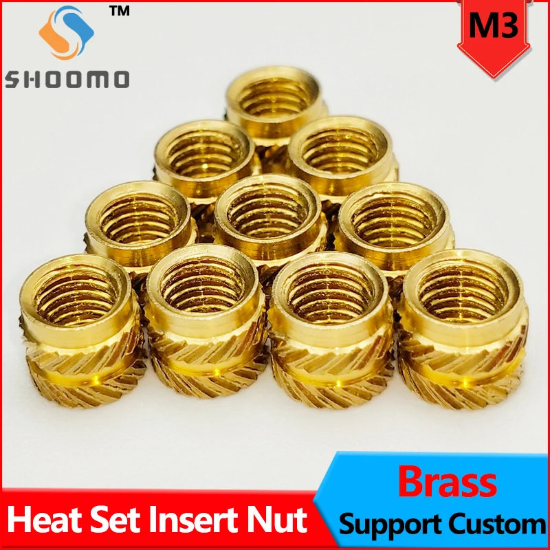 Line the tip of the iron up with the center of the insert, and apply slight pressure while the insert heats up. Once the insert exceeds the plastic melt temperature, the insert will start to descend into the part. Be careful to push the insert down straight into the hole, and not at an angle. Larger inserts may take longer to heat up before they sink into the part. Keep the iron on the insert until it bottoms out in the counterbore, and make sure the insert is flush with the top of your part before you extract the iron.
Note: If you are using a regular soldering iron tip, press the insert in with the side of the tip rather than the point.
8. Let the part cool
After all of your inserts are embedded in your part, let them cool for a few minutes before use so that the plastic has some time to set. You can also use this time to adjust any inserts with the iron if they have not seated correctly.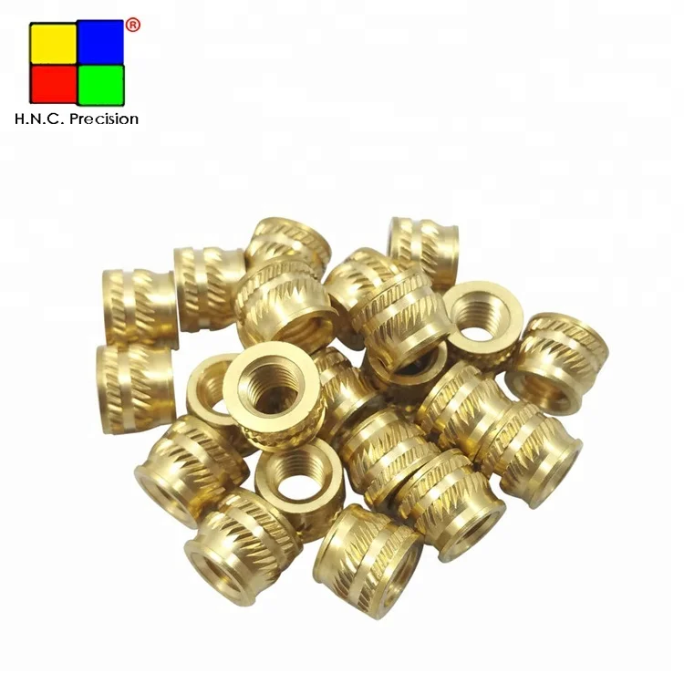
Talk to a product specialist
Making your threaded connections even stronger
Threaded inserts are pretty strong with the insert embedded in the top face of the part due to the knurled external face meshing with the locally melted and reflowed plastic. However, there may be circumstances in which you need even more strength in your connections, and you can use the following trick to resist extreme loads applied to the joint.
Instead of putting the inserts on the face of your part flush with whatever you’re bolting to, put them on the other side of the part instead. This vastly improves the connection strength because when the insert is loaded, the taper of the insert meshes with the taper of the counterbore to distribute forces applied to the bolt. This behavior is highly improved with the addition of continuous fiber reinforcement around the cavity, which further prevents the cavity walls from deforming under load.
Reach out to us for a free sample part to test the strength and durability of our material!
Follow us on Facebook, Twitter, Instagram, and LinkedIn to keep updated with everything Markforged.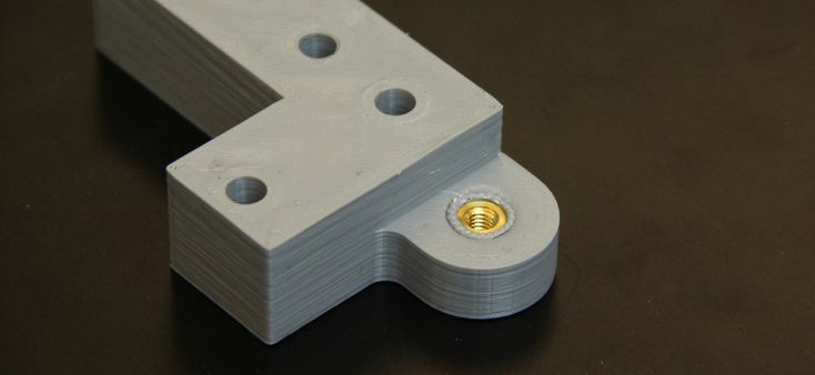
All of the blogs and the information contained within those blogs are copyright by Markforged, Inc. and may not be copied, modified, or adopted in any way without our written permission. Our blogs may contain our service marks or trademarks, as well as of those our affiliates. Your use of our blogs does not constitute any right or license for you to use our service marks or trademarks without our prior permission. Markforged Information provided in our blogs should not be considered professional advice. We are under no obligation to update or revise blogs based on new information, subsequent events, or otherwise.
Never miss an article
Subscribe to get new Markforged content in your inbox
required required requiredSubmit
How to use heat set inserts with 3D printed parts
Arun Chapman29 March 2022
Guide
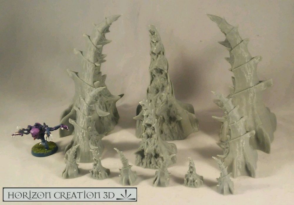
FFF printed parts can be used for more than just ornamental prints.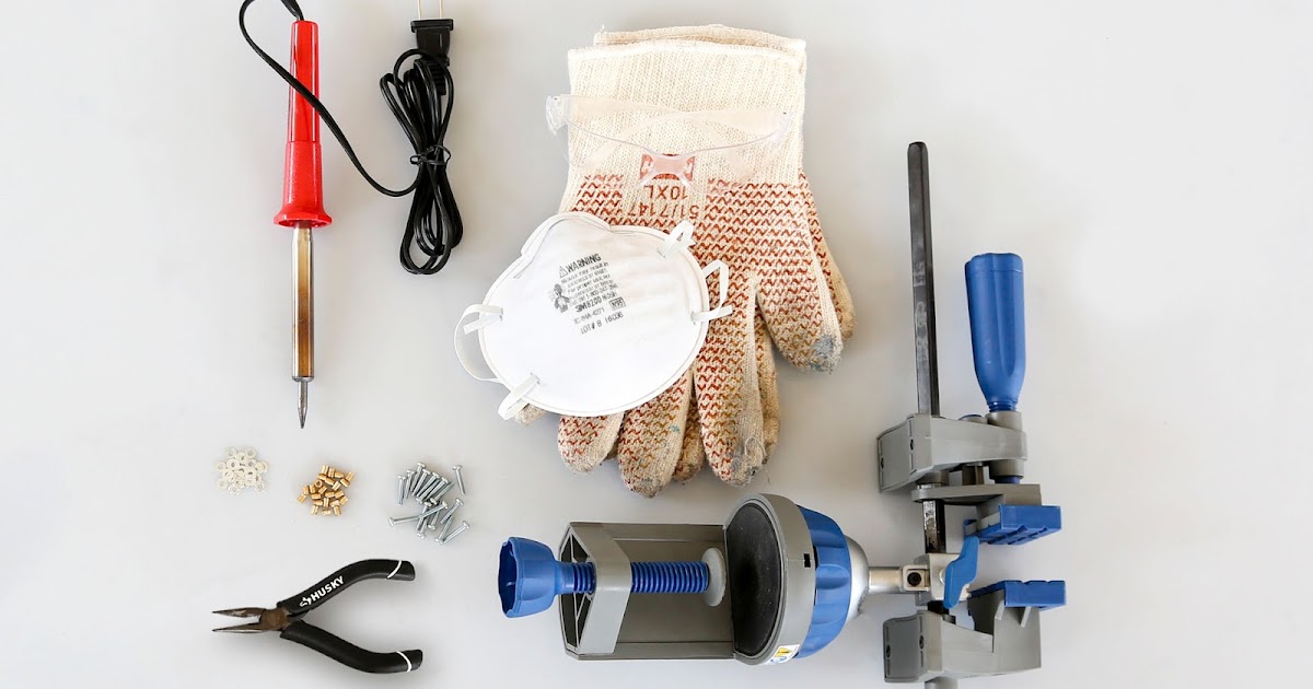 3D printed parts are used in vehicles, factory machinery, and more. Many 3D printers, themselves, use printed parts. However, plastic does not always stand up well to the stresses that these applications put them under. One way to enhance the capabilities of your plastic printed parts are heat set inserts. Read on to find out what they are and how they work.
What are heat set inserts?
Heat set inserts (also known as threaded inserts) are small metal tubes that are threaded on the inside and knurled on the outside. When installed into a printed part, they act as the thread for bolts and screws. They can be placed into a printed part by heating them to a temperature that softens the plastic part to the point where you can push the insert into an appropriately sized hole. Once in place, the insert cools and so does the surrounding plastic, causing it to harden. Leaving the insert secured in place.
Heat set inserts are an easy and effective way to improve your ability to fasten printed parts.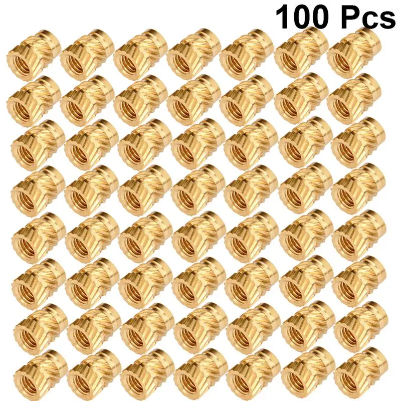 They come in a variety of sizes (M3, M5, etc.), and they are much less prone to stripping and deforming than threads that are printed or tapped into plastic parts.
3D printing is a perfect application for heat set inserts. Although, they can also be used with injection-molded parts.
How effective are heat set inserts?
Heat set inserts can greatly improve both the pull-out and torque resistance of fasteners screwed into your printed parts. The exact effectiveness of the insert is dependent on a number of factors, including the quality of the insert itself, the material used, and the settings used when printing your part. The price of inserts can range from 3-cents per piece to 25-cents or more a piece with the higher-priced ones generally giving better performance.
Higher-strength materials like ABS or PETG are generally a better choice when using threaded inserts as weaker materials like PLA can end up becoming the point of failure, rather than the insert. Flexible materials like TPU are less suitable as the plastics' inherent ability to deform means the insert will not stay in place securely.
When choosing your print settings, the best option is to use a high infill percentage with 100$ infill being preferred. If the part you plan to use an insert with is large and a high infill percentage is impractical, make sure you’re at least using a high wall count (3+) and consider increasing the thickness of your outer walls.
How do you use heat set inserts?
When using heat set inserts, you need the following items:
Heat set inserts are most commonly made out of brass. As the name implies, in order to set an insert into place, it needs to be heated. The most common way to do this is with a soldering iron as you can precisely apply heat to the insert without heating the surrounding plastic more than necessary. Make sure the tip on your soldering iron is appropriate. Many soldering irons have swappable tips and tips are sold which have been specifically sized and shaped for use with heat set inserts.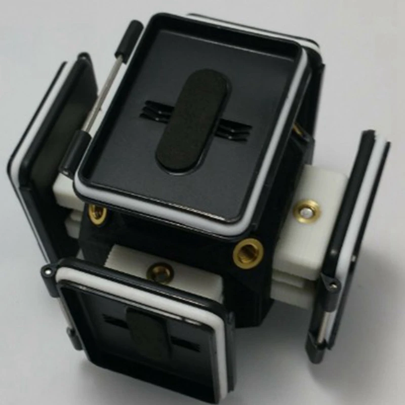
It is possible to use a special press when using heat set inserts but most of the time this is overkill as soldering irons are effective while also being much cheaper and easier to find. The main situation where a press may be better is if you’re planning on using a large volume of inserts or you need to reach an extremely high level of precision and reliability.
You also need a plastic part with an appropriately sized hole for the insert to be placed into. The hole can either be designed into 3D model that is printed or it can be drilled in after printing. When printing a part with the holes included, the dimensional accuracy of your printer comes into play. If the hole is too big, the insert will not stay in securely and if the hole is too small, the insert will be harder to melt into place and you will have to deal with more excess plastic afterwards.
Heat set inserts can be placed into any thermoplastic but plastics with higher melting points are a little easier to work with as there is less risk of overheating and deforming the part. Stronger materials like ABS and PETG are commonly used with inserts as they have stronger strength characteristics which make them more applicable for engineering applications. Avoid flexible materials like TPU.
How to install a heat set insert
Once you are ready, place the insert at the entrance to the hole. Some inserts are tapered on one end to make inserting them easier. Once in place, turn on the soldering iron and let it heat up to the melting point of the material you are using (or just below). Then place the tip of the soldering iron onto the insert itself, making sure not to touch the plastic with the soldering iron directly. After a moment, the plastic around the insert should get soft, allowing to you slowly push the insert into place. Once it’s flush with the part, remove the soldering iron and leave the insert to cool for a few minutes before touching or screwing anything into it.
When pushing in the insert, make sure the exert even pressure from directly above.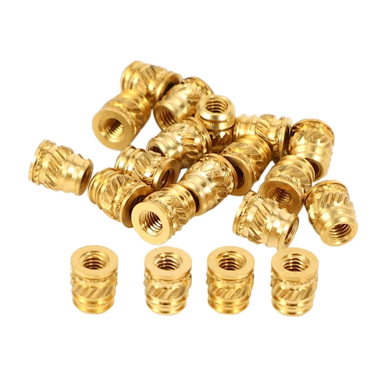 Any twisting or sideways pressure may cause the inserts' final position to be askew, making it difficult or impossible to screw anything into it. Also, if the hole the insert is placed into is too small, it may be that excess material can bunch up and blocked the bottom of the insert. This can normally be cut or melted away.
Once an insert is in place, it is possible to remove it again by essentially reversing the process of installing it. Heat the insert and then pull it out. Beware when doing this that you will take some material with the insert meaning the hole it was originally placed into will be enlarged and may be less reliable when being used to house an insert in the future. It’s also possible to damage the insert by doing this but considering the relatively low price of a single insert, the cost of doing so is negligible.
Heat set insert applications
Heat set inserts can be useful in any application where you need to attach something to a printed part or attach two printed parts together. Some examples include:
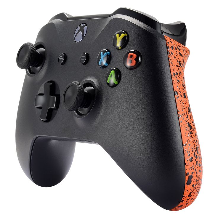
Functional prototypes
Rapid prototyping is an amazing use for printed parts. You can find plenty of examples of where they’ve been used to great effect. Printed parts can also be used for prototypes where all or part of the final product will eventually be made of a different material, such as metal. In these cases, you may want to your printed parts to simulate the fastening characteristics of those materials. Heat set inserts are a good way to do this.
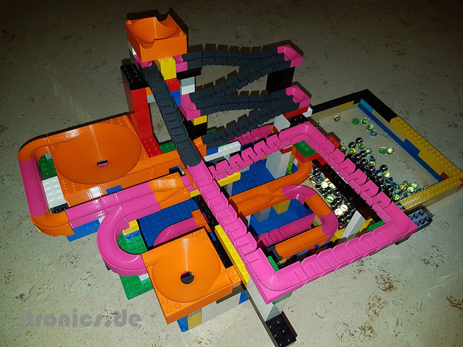
Spares and replacement parts
Sometimes a single part of a larger assembly can be prohibitively expensive to buy in small quantities. In cases like this, a 3D printed replacement is ideal. Heat set inserts allow you to use printed parts even when those parts need to be connected securely or are likely to undergo mechanical stresses.
Azoth is a company that has seen great success in helping companies design parts that not only replace, but in many cases improve, those that were previously in use.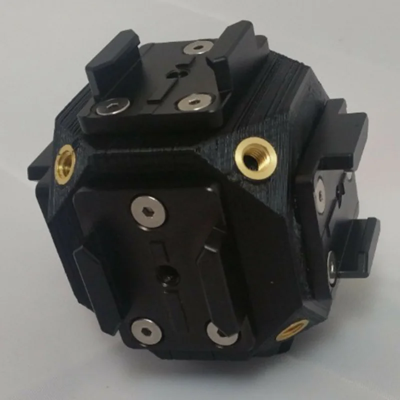 Often for a greatly decreased price.
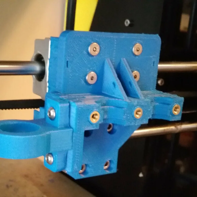
Open source DIY 3D printers
Many modern 3D printers exist because of the advancements made by open-source DIY printers. The founders of Ultimaker originally started building printers as part of the RepRap project. An open-source project founded on the idea of allowing people to use 3D printers to print and build other 3D printers. Ultimaker eventually moved on to designing and building their own high-quality printers but that culture of open source 3D printer building still exists. Many newer DIY printers use printed parts combined with heat set inserts to fulfill that promise of self-replicating printers while also benefitting from the improved mechanical properties that threaded inserts provide.
We hope this article gave you some ideas for new and interesting ways to use your printed parts. If you need more inspiration, you can take a look at some of the exciting ways our customers have used our printers.
Find inspiration
3D Printer Threads and Thread Inserts for Plastic
At Formlabs, we design various functional parts for printing on our stereolithographic (SLA) 3D printers such as the Form 3.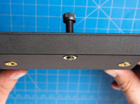 These parts include prototypes used for our own R&D, clamps and fasteners to be used on our production lines, models to check the design before casting the final product in the appropriate material, such as nylon.
Regardless of the application, we often need to connect 3D printed components with screws and threaded fasteners. As the catalog of versatile and reliable engineering polymers grows, the differences between "imitation" prototypes and functional prototypes diminish.
This article is a guide to threading and threading 3D parts with a 3D printer. There are many ways to connect multiple 3D printed parts together, but if you need the ability to repeatedly connect and disconnect components and secure mechanical fastening, there is no real substitute for metal screws.
Do you like to see everything with your own eyes? Watch a video about 3D printing threaded connections and threaded inserts for 3D plastic parts.
White Paper
Download our white paper on stereolithography to find out how SLA printing works, why thousands of professionals use it today, and how this 3D printing technology can be useful in your work.
Download white paper
Let's take a look at some of the threading options for 3D parts we've put together based on years of Formlabs experience and your suggestions. We've ranked these options, starting with the one we think is the best, with the pros and cons of each option for different use cases.
Experience Formlabs print quality first hand. We will send a free 3D printing sample directly to your office.
Request a free sample
Benefits: Strongly connects 3D printed parts without the use of glue. The metal threads are durable and reusable.
Drawbacks: Inserts may loosen as temperature rises.
3D print a sleeve blank with a depth and diameter that matches the insert specifications. Rinse with isopropyl alcohol (IPA) and allow to dry without final polymerization. Insert the insert into the sleeve with a screwdriver and use the screw to secure it completely into the plastic. Then finish curing the part to reduce the creep effect and fix the insert in the plastic even better. Performing this step last reduces the chance that the insert will break the sleeve when screwed in.
Benefits: Connects 3D printed parts very securely. The metal threads are durable and reusable.
Cons: Adhesive required (don't try to use a soldering iron!).
Threaded inserts with heat setting are designed for installation in thermoplastics using a soldering iron with a soldering tip. They can be used in acrylic models and Fused Deposition Models (FDM), but cannot be installed in SLA photopolymer parts, which bend but do not melt when heated.
Check out our detailed guide comparing FDM vs. SLA 3D printers to see how they differ in terms of print quality, materials, application, workflow, speed, cost, and more.
However, the notches and ridges on the heat set inserts make them a very effective thread fastener if you bond them with a two part epoxy or cyanoacrylate adhesive.
Determine the bushing size by the largest diameter of the insert and apply some adhesive before installation. For best results, the part must be completely dry and cured.
Benefits: Nuts are easy to match to any required screw size.
Drawbacks: Side nut slots can eliminate the need for glue, but can make it harder to support the model during printing.
Adding a hexagon socket to the nut press-fit end creates a reusable strong metal-to-metal connection. To increase the twisting force, you can choose a square nut. This nut can also be plastic or have blocking elements. If necessary, a drop of cyanoacrylate glue will help hold the nut in place, but if the design includes a side socket, there is no need for glue. Use a 0.1 mm offset around the press-in nut and clearance around the screw itself.
Benefits: Prototyping uses the same metal products as mass-produced injection molded parts.
Sleeve blanks made from Tough (and Durable) polymer are unlikely to crack if you follow the screw manufacturer's sleeve design guidelines.
Disadvantages: The screws will hold tight, but the threads will not be as resistant to repeated use as metal threads. Standard resins can be used, but the bushing is more likely to crack.
Follow manufacturer's recommendations for core sizes and print with high impact engineering resins (such as our Tough Resin and Durable Resin). Before using the screws, complete the final curing. If you are prototyping an injection molded part that will use tapping or tapping screws in its final assembly, this is a good option for testing.
Benefits: No need to buy special plastic screws.
Disadvantages: The screws will hold tight, but the threads will not be as resistant to repeated use as metal threads.
We have tested screws in our Tough Resin product and found that their use is identical to that of threading screws designed for plastics.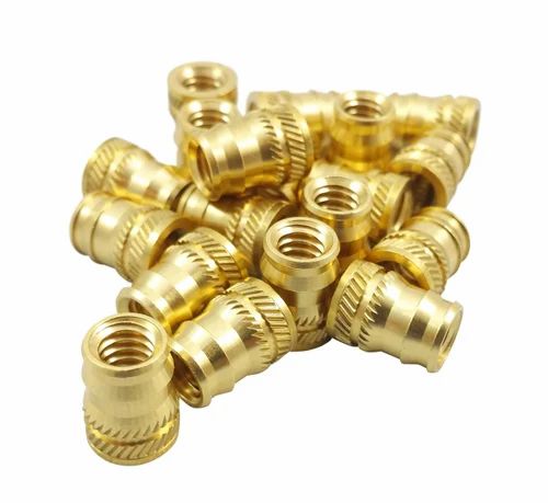 The size of the hole diameter of the threaded bushing must be in the range between the main (threaded) diameter of the screw and the inner diameter. The screw shown is a #8 screw in a 0.16" diameter hole.
Benefits: Can be used for prototyping large and custom threaded designs.
Disadvantages: Not a durable or reusable fastening solution, especially for smaller threads.
3D printed threads from standard resins are better than Tough Resins because they are much harder. 3D printed threads remain relatively brittle, depending on the size of the thread, and are not recommended if the fastening system is to be used continuously and repeatedly.
Thread sizes ¼-20 or larger are generally functional without the need for post-processing. For smaller screws, the threads must be modified to provide better fastening. For example, printing a round thread profile (on a screw and a nut) and using a 0.1mm offset results in a better thread fit and improved wear characteristics.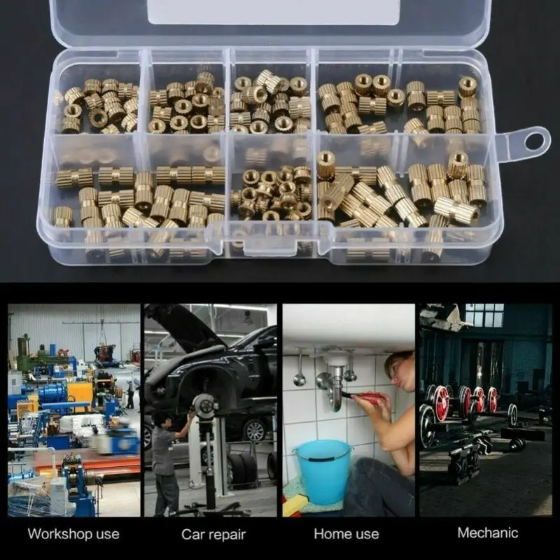 For all screw sizes, it is best to orient the parts so that the supporting structures do not touch the threads.
White Paper
Tolerance and fit design reduces post-processing time and simplifies assembly, as well as reduces material costs per iteration.
Learn more
We hope this guide has provided you with useful information about the mechanical mounting options that can be used for 3D printed components! If you are interested in seeing the model we use for testing, please download the STL file.
Download STL file
Parts mentioned in this manual can be ordered from McMaster using the links below:
- M3 insert with heat setting for plastic
- Brass M3 screw-in insert for plastic
- Galvanized steel hex nut M3
- Galvanized steel hex nut M4
- Threading screw 4-20 for plastic
Want to try Tough Resin, Durable Resin or any other Formlabs 3D printing material in action? Request a free sample!
Request a free print sample SLA
Wide Format Raise3D RMF500 for 3D Printing with Carbon Fiber Reinforced Materials
small-scale production in the industrial sector - RMF500 .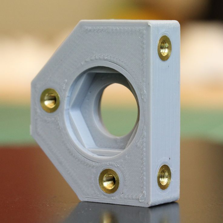 The unique feature of the novelty is combination of the ability to print with carbon fiber-reinforced material (colloquially carbon fiber), wide format and affordability .
We all know that high technology is becoming more accessible every day, and the RMF500 is a prime example of this. There have been systems on the 3D printing market for several years that print carbon fiber composites of similar quality, but, unfortunately, they are not available to all companies due to the very high cost and supply problems. For example, such professional 3D printers are produced by the American company Stratasys - Fortus 450mc, but they are equipped with less technological features and are much more expensive.
Let's take a closer look at what the RMF500 is and how it differs from other 3D printers.
The RMF500 is specifically designed for printing complex parts with high durability. It will enable 3D printing companies to expand their product portfolio with carbon fiber and fiberglass end parts.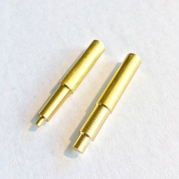 Both materials specially developed by Raise3D, such as PA12 CF, and materials from other manufacturers approved by Raise3D under the Open Filament Program (OFP) will work. Parts made of carbon and fiberglass are more rigid, durable, resistant to heat and shock than parts made of other plastics. For carbon and fiberglass printing, the RMF500 uses silicon carbide nozzles with a hardness of more than 60 HRC.
PA12 CF filament is the result of a long-term development by Raise3D engineers. This is a carbon fiber reinforced filament with increased stiffness and reduced shrinkage and does not require a thermostatic print chamber. The parts obtained from it are light and extremely durable, sometimes they can even be used instead of metal. In addition, the company has developed the PPA GF glass-filled filament specifically for the RMF500 and plans to launch PET-CF, ASA-GF, PPSU-GF and PP plastics for medical use. Raise3D promises that all fiber reinforced plastics will be competitively priced.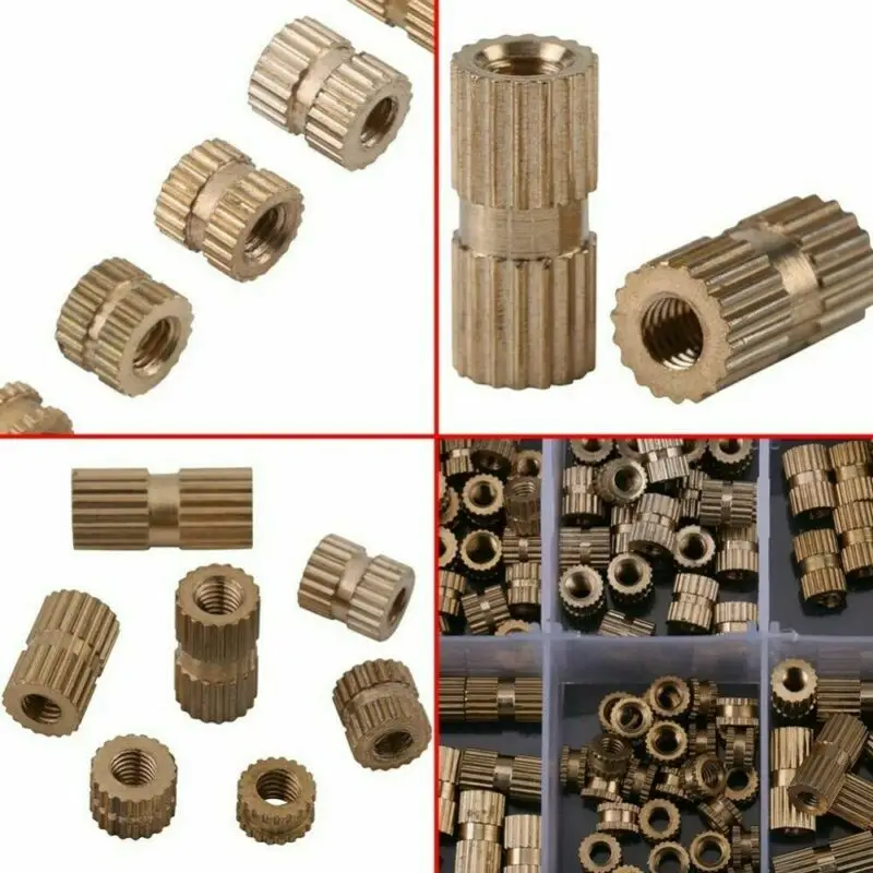
The RMF500 has a huge building area 500x500x500 mm. The size of the build area matters in the production of large parts and small-scale production. For comparison, the print area of the Fortus 450mc is 406x355x406mm.
In the photo: printing a large model with carbon plastic in the RMF500 3D printer from Raise3D.
Repeatability and print speed are very important for low volume production. The maximum print speed of the RMF500, according to the manufacturer, can reach 300 mm/s. Positioning accuracy along the XY axis - 1 micron, along the Z axis - 0.09765 microns.
Synchronous feedback control with 1 µm accuracy reduces speed fluctuations as motor load changes, further improving accuracy. Stability and repeatability of printing has long been a hallmark of Raise3D printers. The FFF technology on which this 3D printer is based allows the production of parts with a high degree of repeatability, high positioning accuracy and uniform extrusion.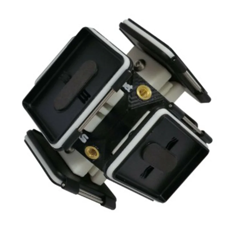 The RMF500 can quickly print large batches of identical parts.
Pictured: production of lots from a large number of parts on the RMF500.
The printer has a printing system with two independent IDEX extruders. It allows you to print with one or two extruders at once. The RMF500 can run two jobs at the same time, further increasing productivity and task speed. The extruders are manufactured using high temperature alloys and industrial ceramic composite materials. These characteristics provide stable and high extrusion speed up to 500 g/h.
The RMF500 has a strong design . The one-piece frame is made of hardened steel. Stainless steel linear guides have a design load of approx. 100 kg. The bearing of the linear guides has minimal backlash and does not require frequent maintenance.
An important detail - Raise3D has developed a special support material for printing with reinforced plastic PA12 CF, which can be easily detached.
Pictured: Parts printed on the RMF500 with PA12 CF filament with special proprietary support.
The RMF500 is equipped with four large compartments for plastic spools. Switching between the main and auxiliary compartments occurs automatically. This feature reduces the amount of time spent threading the filament. The humidity control system keeps the relative humidity in the chamber below 5%, preventing humid air from entering from outside.
What else is there in the RMF500 from nice additional options. The front of the printer has a large 13.3-inch touch screen. Supports connection, management and printing via Wi-Fi and LAN. There is a reliable auto-calibration system from Raise3D.
Carbon fiber printed parts are strong enough to be used in the automotive and aerospace industries. Of course, they will not replace functional parts that have a special load, but their scope can be very wide. Raise3D has already presented the results of the first RMF500 printing and its application.
Pictured: Functional parts, accessory tools and fixtures, car décor printed on the RMF500.
Pictured: Functional parts, accessories and aerospace prototype printed on RMF500.
In the photo: on the left is a prototype of the hinged window mechanism (details are printed with metal filament and carbon), on the right is a carbon fixture. Carbon parts printed on RMF500, metal parts printed on Metalfuse. Printing with fiber-filled plastics does not require a heated chamber, peak power consumption is less than 3 kW. The average power consumption per unit of print area of the RMF500 is 60% lower than the competition.