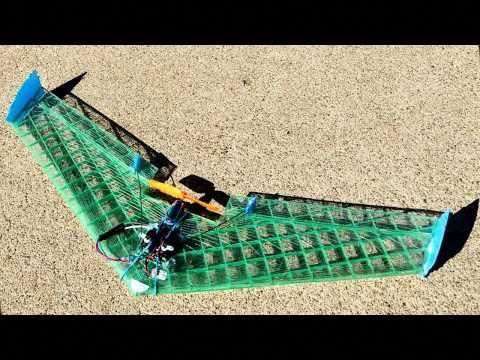
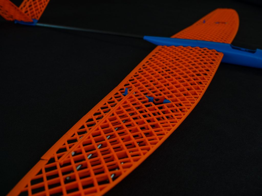
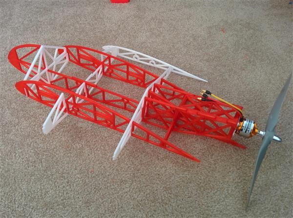
3D printed airplane wing
X-100 Infinity Wing 3D Printed RC Aircraft — 3DAeroventures
$10.00
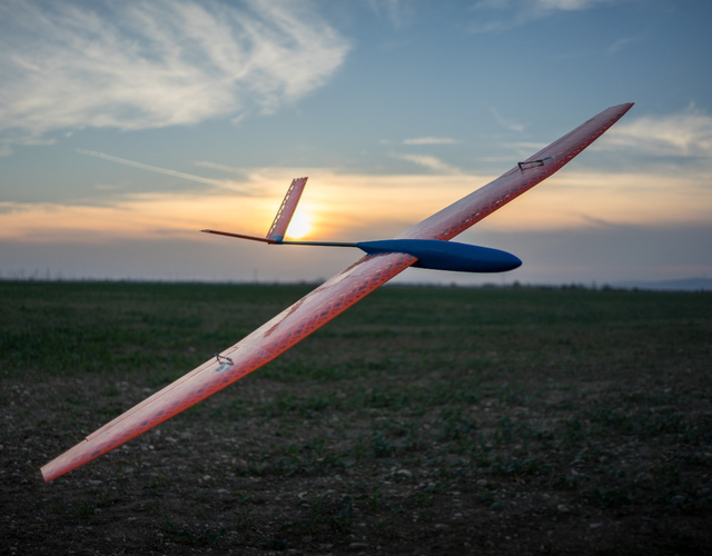
The X-100 Infinity Wing is a 3DAeroventures original design which features a very unique wing configuration that is rarely modeled and seldom seen in full-scale aircraft. Sometimes called a closed wing, joined wing or box wing, this configuration’s unique wing tip design not only has structural benefits, but is expected to come with some aerodynamic advantages, namely the reduction of wingtip vortices. Wingtip vortices form a major component of wake turbulence and are associated with induced drag, which is a significant contributor to total drag in most aircraft. The previous sentence is just science-y aerodynamics talk for: “It flies real nice”.
This “V2” version of the design has been updated for improved stall characteristics, improved print quality, and the ability to print the parts in any material your printer can handle. This version of the Infinity Wing also includes an optional takeoff dolly at no extra cost.
This is a digital product.
Once you make your purchase you will immediately be given access to a link to download the X-100 Infinity Wing files and 3D print it at home. The link will also be sent to you via email. PLEASE NOTE: once you click the download link it will expire in 24hrs. If you have trouble with your download please submit a message through the contact page and we’ll resend the access link.
Add To Cart
Go To My Cart
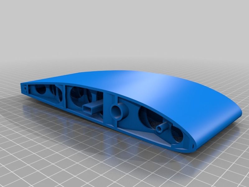
Features:
New “super-structure” design style creates a stronger aircraft and is suitable for printing in various materials including LW-PLA, LW-ASA. PLA, ABS/ASA, and PETG
Simple, 3-Channel setup: Throttle, Aileron, and Elevator (Elevons) requires only 2 servos
Optional Takeoff Dolly Included
Removable wings for easy transportation
3D printable TPE/TPU belly wheel and tailwheel for landing on grass or paved runways
Lightweight, strong design suitable for sport aerobatics
Recommendations for premium and budget electric motors
Upgrade with landing gear and rudder available here.
Included in Your Download:
STL Files
Simplify3D Factory Files (individual parts and grouped builds)
Cura and PrusaSlicer Profiles
Recommended Slicer Settings for Different Materials (Excel and PDF format)
Generic Gcode for i3 style printers
PDF Build Guide
Download the PDF Build Guide
An optional, free upgrade is available to give your X-100 Infinity Wing V2 traditional landing gear and rudder control.Learn more About the Upgrade
These flexible airplane wings are made from thousands of tiny 3D-printed pieces
A team of NASA and MIT engineers has built and tested a “radically” new kind of airplane wing they say could help more efficient planes take flight.
The future of flight is flexible – at least, that might be the case if this new wing design takes hold.
The wings, created by NASA and Massachusetts Institute of Technology (MIT) engineers, comprise thousands of tiny triangles of matchstick-like struts bolted together to form an open, lightweight lattice framework, which is covered with a thin polymer layer.
According to the developers, this forms a mechanical metamaterial with the stiffness of a rubber-like polymer and the lightness and low density of an aerogel. The lattice has a density of 5.6 kg per cubic metre, compared to rubber with a density of 1500 kg per cubic metre.
The material’s mix of stiff and flexible components means instead of requiring separate movable parts such as ailerons to control the roll and pitch of a plane, parts of the wing – or the whole wing – can deform for the same effect.
Mighty morphing wings
According to Benjamin Jenett, a graduate student in MIT’s Center for Bits and Atoms, each phase of flight from take off to landing has optimal wing parameters. Conventional wing designs are a compromise to accommodate these many stages, but that requires sacrificing efficiency.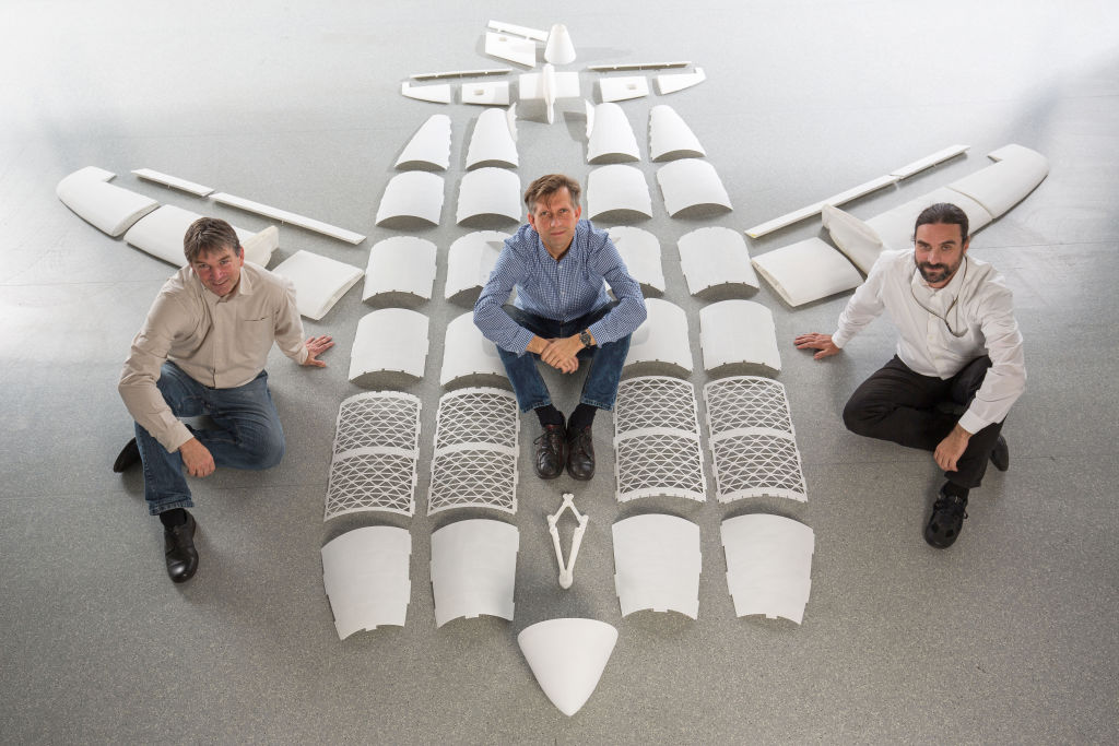
A deformable wing, on the other hand, can change shape as needed for each stage of flight. Rather than use cables or motors to change shape, sections of this prototype wing are designed to respond to stresses – like changes in aerodynamic loading conditions – in specific ways.
The prototype is about the same size as what you would need for a single-seater plane. The new wing design was successfully tested in NASA’s high-speed wind tunnel at Langley Research Center.
For testing purposes, the wing was hand-assembled, but future versions could be assembled by specialised miniature robots. (Image: Kenny Cheung/NASA Ames Research Center)Although it was put together by hand, Jenett said in the future this assembly would be a job for swarms of small, simple autonomous robots (designing and testing this assembly system is the subject of a future paper for the group).
Parts are manufactured using injection moulding with polyethylene resin. Each triangle can be printed in just 17 seconds.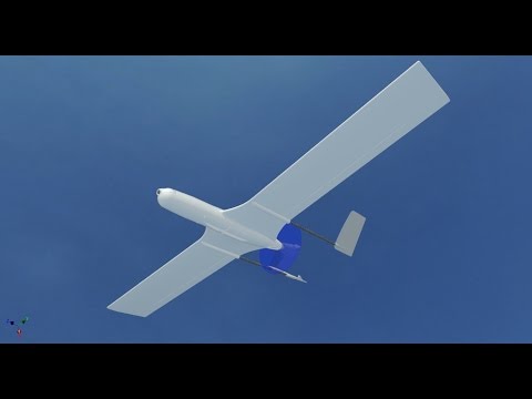 Despite upfront investment in tooling, Jenett said this makes the parts extremely cheap to create.
“We have boxes and boxes of them, all the same,” he said.
Jenett added that the same system could be used to make other structures as well, including blades for wind turbines. As the technology improves, he said structures for spacecraft and bridges could be added to that list.
“You can make any geometry you want,” he said.
Tags: lightweight materialstransportmetametarials3D printingaerodynamicsaeronautical
New Lightweight PLA eSUN for RC Aircraft and Cosplay Released!
News
Publication time: 2021-04-12
2021.04.12
In recent years, remote control aircraft 3D printing and COSPLAY 3D printing props have emerged rapidly with the rapid popularization of 3D printing technology. Compared to traditional production methods, the flexibility and variety of 3D printing gives users more choices and more creative freedom.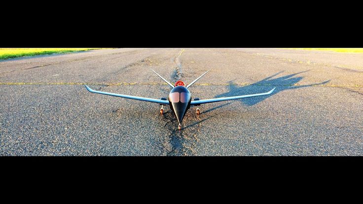
3D Printed RC Airplane Flight Test Video Display:
1.1.4 m test flight video of glider
2.1.8m fpv flying wing flight test video
3. Video of flight tests of a water engine.
All of the above 3D printed aircraft are made from lightweight PLA eSUN ePLA-LW. According to feedback from RC Planes enthusiasts, eSUN ePLA-LW has more noticeable advantages than PLA and other materials that have been used more often.
So, what is the key point when choosing filaments for 3D printing RC aircraft? What are the benefits of ePLA-LW? Let's find out right now!
About 3D printing RC Plane
3D RC aircraft can be divided into 3D printed aircraft and 3D printed parts. 3D printing is all involved in everything from crossover aircraft to aircraft personalization, from functional parts to complete aircraft and helicopters.
As a kind of self-made machine, 3D RC Planes has the advantages of easy production, short hours of manual labor, high image fidelity, much lower production cost than commercial machines, and smooth and natural body curve.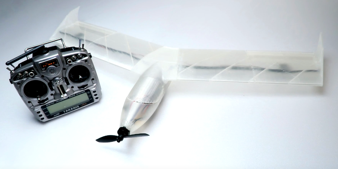 It has a more real appearance than kt and pp self-made carton machines, which are close to or even superior to commercial products. The wing loading can also approach or exceed the kt plate, which is lighter than homemade aircraft like epp. The complexity of the manufacturing process is relatively low. Compared to do-it-yourself machines such as hot cutting foam, fiberglass reinforced plastic, and cork wood, it does not require a large production area, more tools, or complex skills.
The fuselage design is completed by a 3D printer with a high degree of freedom. During the process of creating a 3D RC Plane, a manufacturer can easily change the size of the model, select materials for printing with different properties, and control the density of materials. Finally, compared to commercial aircraft models, 3D RC aircraft tend to be cheaper and have more creative options.
Currently, there are many common materials for 3D RC aircraft. From the relatively widely used PLA, ABS, TPU, PETG, etc. to PLA foam, which has replaced traditional PLA in recent years, it is used according to different user needs and different use cases. The materials are also different.
| Aircraft types | cargo aircraft | Homemade aircraft | |||
| Commonly used materials | EPO foam, sample, FRP | KT board, PP board, EPP, cork, FRP, carbon soldering | PLA+, ABS, TPU, PETG | Wood | ePLA-LW |
| Advantage | Hand fly, tear resistance, scratch and chip resistance, easy to repair, moderate weight | Control wing load, model, size, price, configuration, characteristics, low price, ease of manufacture | Inexpensive and easy to print | Easy to print, low density, light wing loading | Easy to print, low density, light wing loading, freely adjustable strength/foam ratio, good surface finish, light coverage, drop resistance, easy repair |
| Disadvantages | High performance limitations, no cost advantage, high production complexity and no modifications | Long working time and poor surface transition | Overall heat resistance, high density, heavy load like a real wing, general adhesion between layers, no drop | General heat resistance, general adhesion between coats, not drop resistant, not easy to repair | General temperature resistance |
The appearance of PLA foam is small, but it has obvious advantages as an RC Plane material. The most important thing is lightness. The RC aircraft printed with PLA foam has lighter weight than KT board, EPP board, PP and other RC aircraft pursuing light wing loading. At the same time, PLA foam can also adjust the temperature of the printing nozzle to change the density of the material, from high-strength and heavy plastic mold to balsa wood density and foam density, thus realizing more creative possibilities.
About ePLA-LW (lightweight PLA)
eSUN ePLA-LW (also known as foamed PLA) is specially designed for RC aircraft, drones and COSPLAY. Compared with WOOD, ePLA-LW has a more stable interlayer bond, and the foaming speed and strength can be controlled by adjusting the printing temperature. Use active foaming technology to produce lightweight, low density PLA parts.
ePLA-LW Capabilities:
1. Low density, up to 0.54 g/cm³;
2. Volume foaming ratio 220%, to print the model of the same volume, 1 roll of ePLA-LW can be used as 2. 2 rolls of regular PLA;
3. Foaming makes the layer lines almost invisible, and the surface of the printed product is matte and delicate; At about 210-270℃, this material starts foaming during printing, increasing the volume by almost 1.2 times, and the extrusion speed when printing can be reduced to 45% to print light parts.
4. Strength and foaming degree can be adjusted freely;
5. Excellent interlaminar strength, explosion-proof and easy to repair;
6. The printed model is easy to paint and has a strong adhesion to the surface.
For the same model situation and the same speed, using lighter PLA can make the RC Plane lighter to fly and slower to stall. For RC aircraft, in case of balanced strength, maximum weight reduction can significantly improve its performance.
ePLA-LW applications:
ePLA-LW is mainly used for making light parts, and is widely used in DIY RC aircraft, drones and COSPLAY props.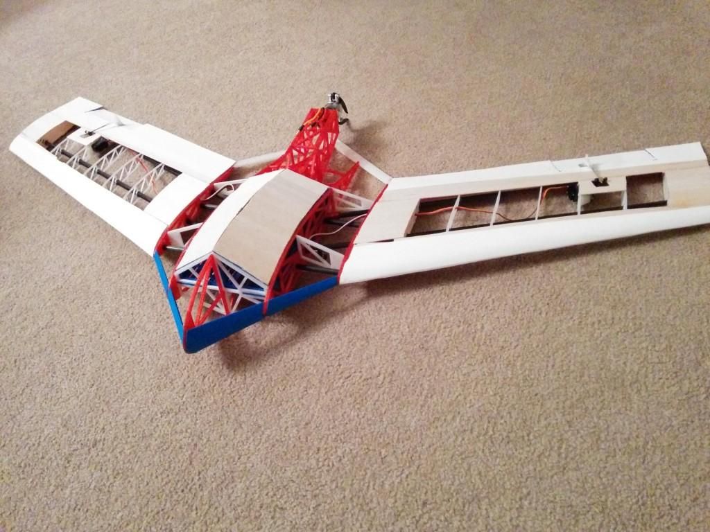
RC Plane 3D printed display:
ePLA-LW parameters:
1. Non-foamed yarn physical characteristics:
| 3D 0028 | 测试 方法 / 标准 | ePLA-LW |
| 熔融指数 | GB/t 3682-2000 | 8.1 (190 ℃ / 2.16kg) |
| 密度 | GB/t 1033-86 | 1. |
| 悬臂梁 缺口 冲击 强度 | GB/t 1843-96 | 8.58 kJ / ㎡ |
| 拉伸强度 | GB/t 1040-92 | 32.2 MPa |
| | GB/t 1040-92 | 68.90% |
| 弯曲强度 | GB/t 9341-2000 | 41. |
| 弯曲模量 | GB/t 9341-2000 | 1701 MPa |
 2 g/cm ³
 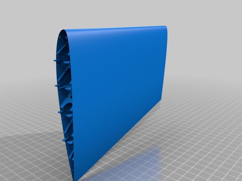 31 MPa
 2. ePLA-LW print options:
| Material name | ePLA-LW |
| Recommended print temperature | 190–270 ℃ |
| Print temperature without foam | 190–210 ℃ |
| Foam printing temperature | 210-270 ℃ |
| Maximum foaming temperature | 270 ℃ |
| Maximum foaming speed (270℃) | 122% |
| Lowest extrusion speed (270℃) | 45% |
| Base plate temperature | 45-60 ° With / without heating (Mask paper, hard glue PVP, GRP, CFRP, PEI) |
| print speed | 40-80 mm / s |
3. Comparison of ePLA-LW vs wood filament:
| Thread | Wood | ePLA-LW |
| Foaming process | Foaming during production Nofoaming when printing | No foam during production Print foam |
| Interlayer bonding | General | Strong |
| Density | 0.7 | Up to 0.54 |
| Foam factor | No | 210-270℃ |
4. Foam ratio at different temperatures
| Temperature / ℃ | 200 | 210 | 220 | 230 | 240 | 250 | 260 | 270 | 280 |
| Foaming rate /% | 0 | 0 | 11 | 33 | 82 | 100 | 122 | 122 | 82 |
| Volume ratio/% | 100 | 100 | 111 | 133 | 182 | 200 | 222 | 222 | 182 |
| Extrusion speed /% | 100 | 100 | 90 | 75 | 55 | 50 | 45 | 45 | 55 |
| Density / g / cm³ | 1. | 1.2 | 1.08 | 0.9 | 0.66 | 0.6 | 0.54 | 0.54 | 0.66 |
| speed | 40 mm / s | ||||||||
 2
2 5. Temperature vs. speed table
The
eSUN ePLA-LW has been acclaimed by DIY enthusiasts since its testing stage. If you have any questions, please contact us!
Recommended reading:
1. ePLA-LW New Features and Industry Application Introduction
2. Application of 3D printing in RC aircraft.
3. 3D printing RC aircraft, what are the characteristics and advantages of different materials?
Contact information:
Phone: 0755 26031978
Email: bright@brightcn. net
net
QQ: 2304729480
WeChat: GWWYeSUN
Or leave a message at the end, we will contact you shortly!
USING 3D PRINTING IN SOLID STATE MODELING AND TESTING OF AIRCRAFT WING
A.
Don State Technical University, Rostov-on-Don, Russian Federation ya_germes@,mail. sh [email protected]
The article focuses on the study of the properties of 3D printing when creating a model of an aircraft wing part in a special program. Further testing is carried out in order to improve the properties and parameters of the created solid object. The optimal values of the input technological coordinates are established to obtain the best result.
The importance of the problem of using 3D printing in modeling objects, the relevance of further research and subsequent use of 3D materials with improved properties and parameters in construction and technology are argued. Keywords: 3D printing, 3D printer, modeling, solid object, aircraft wing, scatter plot, model stencil, wind tunnel.
UDC 744.4
USE OF 3D PRINTING AT SOLID-STATE MODELING AND AIRCRAFT PLANE TESTING
Goncharova T.V., Filippova A.A.
Don State Technical University, Rostov-on-Don, Russian Federation
[email protected] [email protected]
The article considers 3D printing properties in the creation of an aircraft plane model in a special program and further testing to improve the properties and parameters of the created solid-state object. Optimum values of the entered technological coordinates for obtaining the best result are established. The paper justifies the importance of the problem of 3D printing use when modeling objects and the relevance of further research and the subsequent use of 3D materials with the improved properties and parameters in construction and equipment.
Keywords: 3D printing, 3D printer, modeling, solid-state object, aircraft plane, point chart, model cliche, wind tunnel.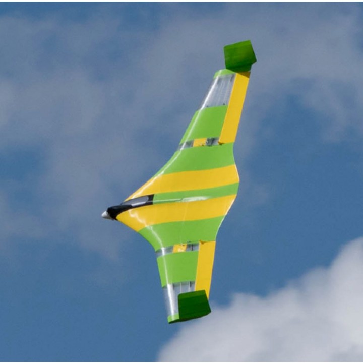
Introduction. One of the widely discussed topics of the 21st century is 3D printing and its application in various fields. One such area is the modeling and testing of parts of an aircraft wing.
Various schools in some countries already have modern enough equipment to allow this type of testing.
First you need to understand what 3D printing is. In short, this is the construction of a real object according to a 3D model created on a computer. To get anything with this type of printing, you need a 3D printer, the necessary materials, such as special cartridges, and, of course, imagination [1-6]. With the help of such tools, people have already learned how to print various objects: spare parts for a 3D printer, artificial houses for fish - corals, food, as well as some parts of the body. And each object, in its own way, is unique, and each can devote a separate time for discussion.
Back in 1984, Charles Hull pioneered a technology called "stereolithography", which we now know as "3D printing". A few years later, he received a patent. Without stopping on his achievements, he founded the company "3D Systems" and created a "stereolithography apparatus". Already in 1988, an improved model "SLA-250" was released, the principle of which is applied to this day.
Statement and analytical solution of the problem. One of the most interesting projects to explore in this area has been a project to model a part of an airplane wing using a 3D printer. A huge advantage of this testing technique is that it is possible to predict whether the aircraft will be able to take off at all or not [7]. Of course, this is not a 100% test, and engineers then conduct a large number of tests for the reliability of forecasts and for strength when developing a functional object.
The modeling project for a part of an aircraft wing, which was carried out during the study, consisted of several stages. The first stage was the creation of the model itself in the special FoilSim program (Fig. 1). Thanks to this program, you can see how the air flow will flow around the wing. The program is quite clear to use, so it was very easy to tweak the coordinates to get a better result [8].
Fig. 1. Entering coordinates in the FoilSim program
The second stage was to use the coordinates that were obtained at the previous stage for a visual representation of the future model. After entering the data into the Excel program, a scatter plot was built, which helped to verify the symmetry of the wing in the section (Fig. 2).
Fig. 2. Dot plot
The third stage consisted of several parts. For even more precise visualization, a foam model is first created. To do this, using all the previously obtained data, a model stencil was created in the Autodest Inventor program. To attach the stencils to the foam, it was necessary to make two holes on each side: one closer to the front of the wing, and the second closer to the back. After printing the stencil, it was glued onto an aluminum sheet for
strength. Then the stencil was cut out along the given lines, and the holes were punched with nails. Next, the finished stencils were attached with the same nails to the foam. With the help of a special machine for cutting foam plastic with a hot metal string, they were able to get a finished model of a part of an airplane wing (Fig. 3).
Fig. 3. Model of the aircraft wing part
The second part of the third stage consisted of testing the obtained model in a wind tunnel. In order to fix the foam wing in the installation, it was necessary to glue a metal mounting ledge. Since the part was about the size of a palm, there was no need for too much installation.
The final stage of the project consisted of printing the product and testing the already 3D model in a wind tunnel. It was very interesting to watch the printing process, as the printer did the most difficult job. The process itself took no more than two and a half hours, and by the next lesson you could see the details.
In general, we can say that the authors are very lucky that there is such a technology that continues to develop every year. Being able to print whatever the imagination can think of is very convenient. Despite the unlimited possibilities for printing, the process itself does not take a lot of time and is quite practical. This technology is under development, so there are problems with printing very small parts. The principle of printing is layer by layer, so if some kind of failure in the program suddenly happens, the part will be damaged.
Conclusion. There are several positive factors of using 3D printing in the curriculum. One of the advantages is that students get a visual idea of how this or that object should actually look like, as well as check its functionality. The process itself involves students in the work, and the stages of the tasks contribute to the development of spatial imagination and problem-solving skills in construction. The only negative factor is the cost.
Convenience, speed, unlimitedness can also be referred to as positive factors. Of the negative factors, errors (inaccuracies) and complex work with small details can be distinguished.
In fact, the use and popularity of 3D printing continues to grow and in a few decades every educational institution will be able to introduce this kind of testing of various parts.
References 1. 3D printing - the pros and cons of various technologies, and implementation on specific examples / 3Dmaker. - Access mode: http://www.interface.ru/home.asp?artId=36742 / (date of access: 02/07/2019).
2. Classification of 3D printers (7 3D printing technologies) / Habr. - Access mode: http://habr.com/ru/post/208906/ (date of access: 02/07/2019).
3. 6 challenges 3D printing has yet to overcome / IT business. - Access mode: http://www.itbusiness.ca/blog/6-challenges-3d-printing-has-yet-to-overcome/ /51152/ (Accessed: 02/07/2019).
4. What is 3D printing and 3D printer / Make 3D.