Gcode simulator 3d printer
The 5 Best G-Code Simulators for Machining and 3D Printing
A good G-Code simulator can make the difference between a successful manufacturing process or an expensive failure. Here are some of the best simulators.
Debugging is a vital part of any programming task. This is certainly true with programs that will interact with the physical world like those used to control CNC machines, 3D printers, and robotics.
Any mistake in the programming of these physical machines could cause real damage to the environment, the machine itself, and even to human workers in the case of some robots.
G-Code simulation is probably the best way to ensure that you have written your program to a high standard. Although very few people these days write G-Code by hand — we tend to use CAM programs — there is still a huge benefit to checking your program in a simulator before loading it into your physical machine.
Here is a list of some of the best types of G-Code simulator that you can use these days.
What is a G-Code Simulator?
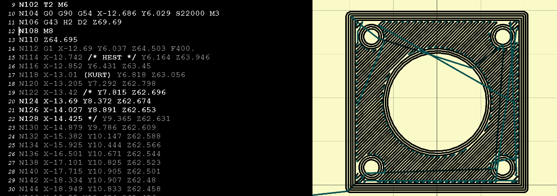
A G-Code simulator is a type of software tool that provides a virtual representation of a CNC machine’s tool path made by following the instructions in a G-Code file. They range from simple simulators that output a single image of the tool path to complex tools that can detect collisions and plot the path in 3D.
The basic purpose of a G-Code simulator is to give you a way to see how the machine tool will move. Without this, the only way to debug your program is to test it out on the machine itself… and by then it’s too late to avoid disaster.
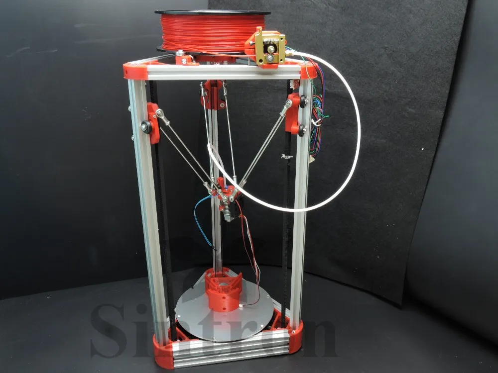
G-Code simulators have experienced a resurgence in popularity over recent years thanks to the rise of 3D printing. Hobbyists and professionals alike need a way to see a 3D printed item before they spend hours printing it. A good simulator provides a quick and easy way to achieve this.
The 5 Best G-Code Simulators for Machining and 3D Printing
There are quite a few options for simulating your G-Code out there. Some of them are okay, others are a waste of time.
Here are 5 types of G-Code simulator that are all good in some situations. Which you pick depends on your unique needs for this machining or 3D printing application:
1. Stand-alone G-Code Simulator
There are some simple software tools available that will quickly simulate your G-Code file and show you the path. In general, they don’t interface with CNC machines or 3D printers, but they at least give you the confidence that your program “draws the shapes” that it’s supposed to.
Some notable examples include:
- NC Viewer a handy online tool for quick visualization.
- CAMotics an open-source simulator for 3-axis machining.
- G-Code Q’n’dirty another open-source web tool.
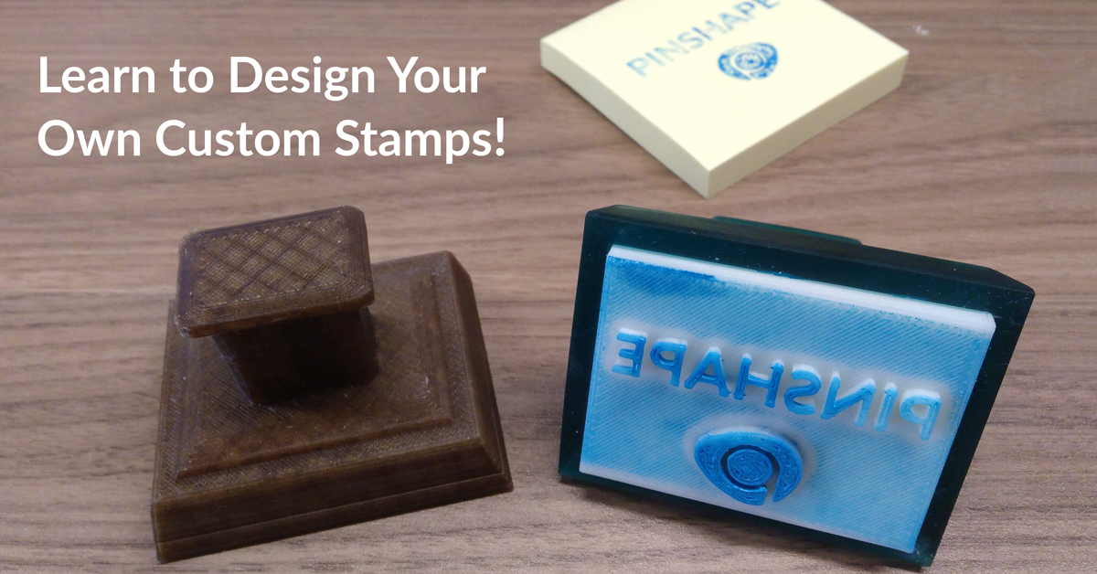
2. Slicer Software (for 3D printing)
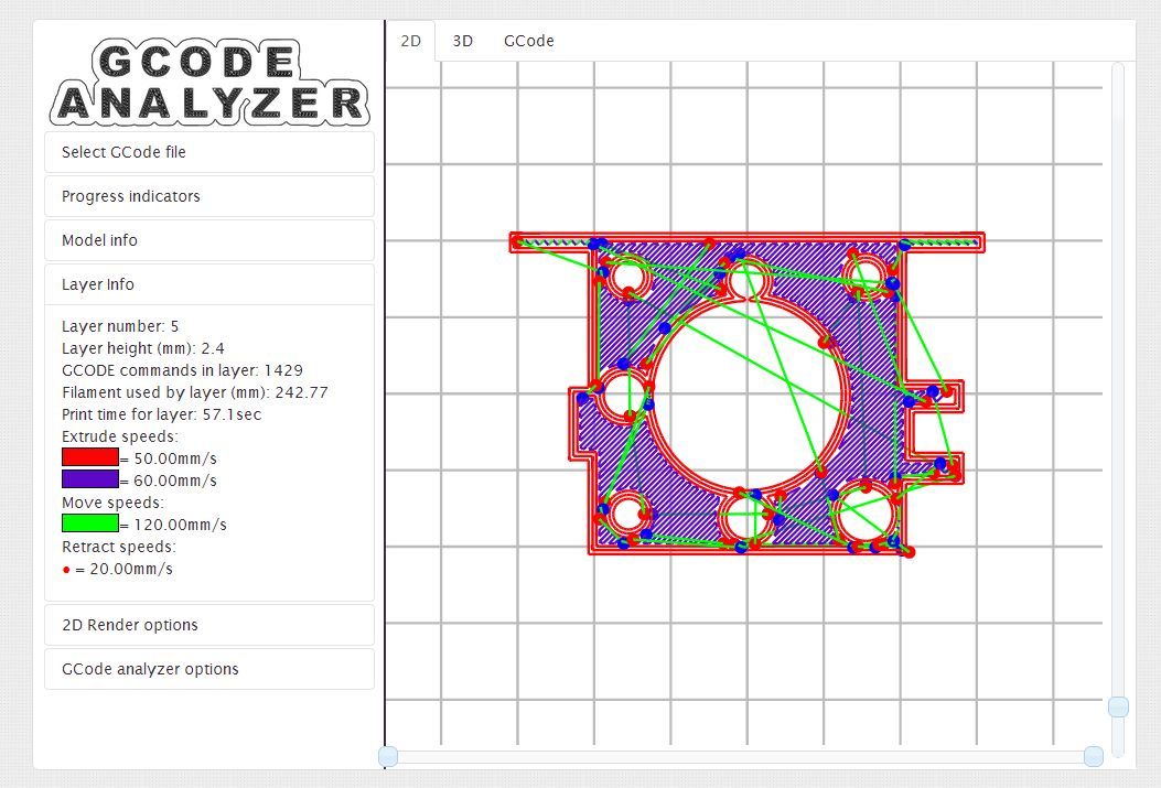
If you are using G-Code to program a 3D printer, your Slicer software may be able to give you a visualization of what the final printed item will look like.
A Slicer is a software tool that turns your CAD model into G-Code.
For example, RoboDK users often use the free tool Slic3er when they are using robotic 3D printing. This tool allows them to visualize the item that they are going to print before they send it to the robot.
Slic3r can also perform some of the functions of a dedicated G-Code simulator, such as estimating the time it will take to print the object and repairing incomplete 3D files.
3. RoboDK for Robotic Machining and 3D Printing
If you are considering using a robot for your machining or 3D printing, probably the best option is RoboDK (of course, we would say that, wouldn’t we?… but it’s also true).
RoboDK’s machining and printing wizard works with G-Code.
You can load a G-Code file into the software then easily simulate the path. Then, with the same software, you can send the program directly to the robot’s controller, without having to do any robot programming at all!
Not familiar with robotic machining? Check out our introductory post.
Didn’t know robots could do 3D printing? Here’s a video:
4.
 Libraries (e.g. MATLAB or Python)
There are some situations where you might want to perform some more advanced analysis on your G-Code or link with your own programming. Perhaps you are using the code as part of a research project or you are developing your own 3D printer.
In such cases, it could be helpful to use a G-Code library for your preferred programming language.
For example:
- G-Code Reader is an extension for MATLAB.
- PyCNC is a library for Python.
- Gsim is an open-source 2D simulator written in Python.
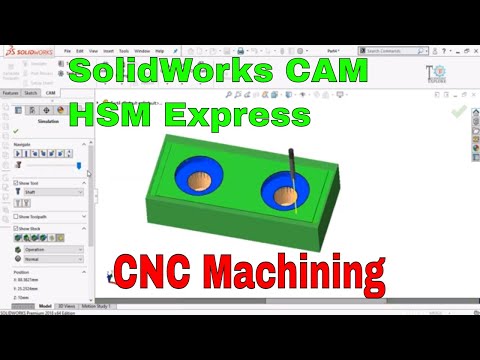
5. Your Favorite CAM Package
Computer-Aided Manufacturing (CAM) programs are how many of us generate our G-Code files in the first place.
Popular CAM packages (which also include plugins for RoboDK) include:
- MasterCAM
- Inventor
- Fusion 360
Many of the leading CAM packages also have the capacity to simulate your G-Code. Often, if you want to link the software directly with your CNC machine or 3D printer, it will require you to purchase an extra add-on license, so weigh up the pros and cons beforehand.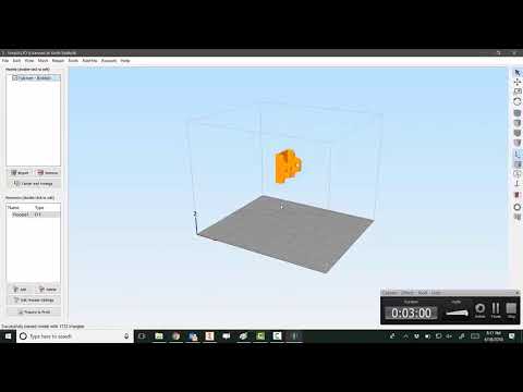 However, simple simulation can usually be achieved within the CAM software itself.
How to Pick the Best Software for You
There are clearly several ways to simulate G-Code!
But, which is going to be the best software for you? The answer depends on your situation.
If you are a hobbyist who is just using G-Code to program your home 3D printer, for example, one of the open-source, stand-alone simulators or Slicer software will probably be the best option.
If you are a researcher or programmer looking to delve deep into the simulation, one of the MATLAB or Python libraries might be worth checking out.
Finally, if you are working in industry, however, you will want a piece of software that is easy to use, robust and won’t give you any unnecessary headaches. For robotic machining or 3D printing, RoboDK is a good option. For all other CNC, look at a decent CAM package.
What questions do you have about G-Code simulation? Tell us in the comments below or join the discussion on LinkedIn, Twitter, Facebook, Instagram or in the RoboDK Forum.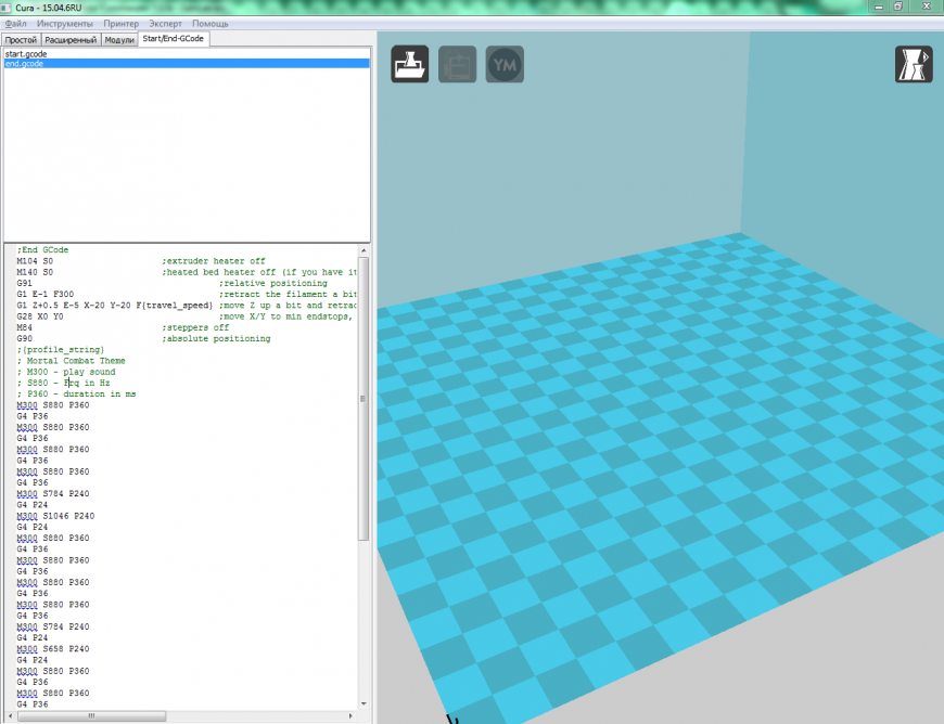
5 Best G-Code Simulators for Machining and 3D Printing
An impressive G-Code simulator can demarcate between a thriving process and an expensive failure. Programs that interact with the physical world to control robotics, 3D Printers, and CNC Machines perform one of the most vital tasks of programming, i.e., Debugging. Any loophole in the programming of these imperative physical machines can cost expensive and hazardous damage to the human workers, machines, or even the environment.
A G-Code simulator is a software tool through which the tool path of a CNC machine, which is made by following the instructions in a G-Code file, can be virtually represented. G-Code simulators can be simple simulators with a single image of the tool path, or they can also be complex tools that can detect collisions and plot the path in 3D.
Some important G-Codes that are used with 3D printers are:
For more about programming 3D printers with G-Code: 3D printer programming with G-Code
This G-code simulation for online visualization is a great tool for testing skills. They give a solution to see how the machine tool will move and provide a quick and easy way to simulate G-Codes for machines and 3D Printers.
There are many ways to simulate G-Code, and it requires the best software to process it. For newbies and hobbyists, open-source or stand-alone G-Code simulators can check programs for CNC machines and 3D printers.
Whereas G-Code simulators from Python libraries or CNC turning centres would be worth checking out for researchers and professional programmers. These also work well for experts working in the industry who want to use convenient software that is user-friendly and robust. https://www.tsinfa.com/CNC-Turning-Center/
This is a simple yet effective software tool that shows the path by professionally simulating G-Code files. Although it does not interface with CNC machines or 3D printers, it helps draw relevant shapes that it is supposed to. For example, an NC Viewer is a handy online tool for quick visualization.
A Slicer is a software tool that converts your CAD model into G-Code. While a G-code simulator may sound enticing, but there are chances that we may already be using it in programs while operating 3D models using the slicer software. This 3D slicer software makes a 3D model 3D printable, slicing it into horizontal layers according to the set layer thickness and generating a road map for the nozzle.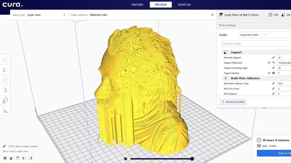 Hence, the printer understands the instructions well
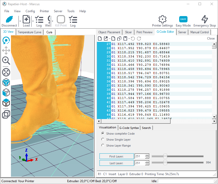
The slicer software also operates the print settings of a 3D printer. The slicers use the layer viewing mode, the G-Code simulator, which generates a 3D simulation and shows how each layer is built, layer by layer. This mode helps to identify when the model may fail when 3D printing starts. Different colours are used to indicate various types of lines and structures to analyze each step of the 3D printing process and see what it looks like.
Almost every slicer program offers a G-code preview. However, experts in the industry may require serious 3D printing software to understand simulations. These tools help identify all relevant parameters like temperature, structural stresses, and the part’s performance under load.
This works as a robot for machining, like CNC Turning or 3D printing, and effectively works with G-Code files that can easily be loaded into the software. This can easily simulate the path, after which the program can be sent to the robot’s controller without having to do much robot programming.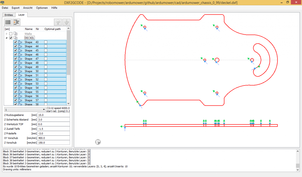 Here are some benefits:
For experts and researchers, libraries are helpful to use a G-Code for the preferred programming language. This is the advanced analysis on G-Code or link with CNC programming and can be used as part of a research project or while developing a 3D printer. Some common examples are G-Code Reader as an extension for MATLAB, PyCNC as a library for Python, and GSIM as an open-source 2D simulator written in Python.
These applications can help you automate the entire path – from research to production and complete tasks more easily than with custom programming. MATLAB and Python can help the professional programmer delve deeper into the simulation and meet the desired objective.
Computer-Aided Manufacturing (CAM) programs are how the G-Code files are generated in the first place. The renowned programs include Fusion 360, Inventor, or MasterCam. These can simulate G-Codes and link the software directly with CNC machines or 3D printers. Some of its more important features are:
The Objective of G-Code Simulators is to show a way how the machine tool will move.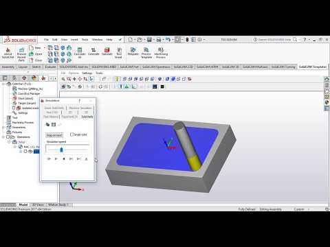 As discussed, there are quite a few options available for simulating G-Codes. Whether working as a hobbyist, a professional programmer, or in the industry, G-Code Simulators are easy-to-use and robust software that will save you from unnecessary headaches.
Also, check out our very own CNC simulator from NCViewer.
Vincent Hua is the Marketing Manager at He is passionate about helping people understand high-end and complex manufacturing processes. Besides writing and contributing his insights, Vincent is very keen on technological innovation that helps build highly precise and stable CNC Machinery.
Free SCAD file G - Code
Brio Toy Wooden level crossing with 5 joints - improved version
1 €
7" touch screen KD070V02
0.50 €
Battery locomotive for wooden rails
€3.99
Retractable building plate compatible with Duplo
2. 49 €
49 €
Another Cube Gear
3.50 €
Level for drilling machine
2.99 €
Anycubic Kobra SD Card adapter (regular size)
2,50 €
Customizable electronic PCB housing
Free
nine0005The best files for 3D printers in the Tools category
Snowballmaker
Free
Pentax K-01 SMC DA-40mm lens cover
Free
Paperclip Bookmark
Free
Ball bearing
Free
Ski binder
3 €
Print In Place PCB-Holder / Gripper
Free
COVID 19 - DENTAL ASPIRATOR - VACUUM
2,82 €
Star Trek TNG Phaser
Free
Bestsellers in the Tools category
Paint stand with scissors
5. 19 €
19 €
Fire hydrant container
1.88 €
ARTEMIS -> Shop for Alligator 2 || 6.5" arrows || Repeating crossbow
6.25 €
INDICATOR FOR BETTER BED LEVELING FOR ENDER 3 V2
2.81 €
ENDER 3 S1/PRO SPRITE, HOTEND 4020 OR 5015 FAN PROBE NO Y OFFSET
€2.28 -twenty% 1.82 €
ENDER 3 S1/PRO SPRITE, V3 AIR DUCT 5015 OR 4020, LED strip
€2.69 -twenty% 2.15€
Phone holder
2.44 €
Cut-Man - PET bottle cutter with handle!
€3.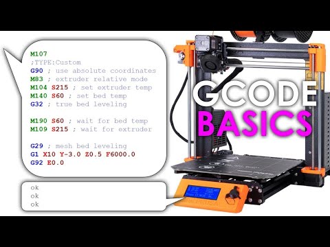 49
49
Cooling system Minimus Hotend
2.33 €
Shrek Pooping Toothpaste Topper
2.82 €
209Flash Bang Machine / Ukrainian Hot Potato
0.94 €
Case for Chill Buddy lighter
0,93 €
SUPERBOX
1,50 €
Ender 3 S1 Air duct for stock fan
€1.20 -10% 1.08€
Display holder FLSUN v400
€9.99 -fifty% 4.99 €
Quick Print Paint Bottle Rack (6 sizes)
2. 86 €
86 €
Do you want to support Cults?
Do you like Cults and want to help us continue our journey on our own ? Please note that we are a small team of 3 people, so it is very easy to support us in maintaining activities and creating future developments of . Here are 4 solutions available to everyone:
-
AD: Disable your AdBlock banner blocker and click on our banner ads.
-
AFFILIATION: Shop online with our affiliate links here Amazon. nine0006
-
DONATIONS: If you want, you can donate via PayPal here.
-
* INVITE FRIENDS: * Invite your friends, discover the platform and great 3D files shared by the community!
G-CODE in Russian for 3D printing (Mini-Reference)
Often, for high-quality printing, and especially when selecting print parameters, it is necessary to be able to read and edit the G-code during calibration.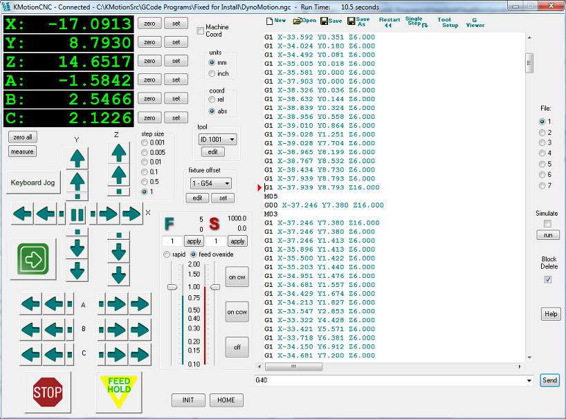 nine0006
A banal example: setting your own values for the "Temperature Tower" or creating start and end blocks of codes in slicers for a specific printer.
On some sites (like reprap.org/wiki/G-code) on the Russian-language pages, the commands are only partially described in Russian, and the rest in English. On some domestic sites, the commands are translated into Russian, but some are given with errors - stupidly copy-paste a clumsy translation.
Tired of searching through different sites, trying to find the CORRECT description of a particular command and its parameters. nine0006
I made myself such a mini-reference book. I'll be glad if anyone else finds it useful.
I tried to describe the maximum number of commands used, except for very specific ones.
(Yes, special commands for deltas, for example, sorry, I consider them specific and not necessary for me)
However, most commands are supported by all printers and firmware.
Attention! Compliance of commands and parameters is checked only for Marlin firmware.
G-commands
G0(G1) Xnnn Ynnn Znnn Ennn Fnnn – movement.
G0 - fast idle
G1 - linear working travel
Xnnn, Ynnn, Znnn – coordinates.
Еnnn - amount of extruded material in mm (with negative values - retract).
Fnnn – travel speed in mm/min (this speed will be used until the next change).
G0 X12 (will move 12mm in X) nine0006
G0 F1500 (Set travel speed to 1500 mm/min.)
G1 X90.6 Y13.8 E22.4 (Move 90.6mm X and 13.8mm Y while extruding 22.4mm of material.)
G4 .
Pnnn - Timeout, in milliseconds
Snnn - Timeout in seconds.
"G4 S2" and "G4 P2000" equivalent
G10 - Plastic rollback (Retract)
Filament rollback according to M207 settings.
G11 - Plastic feed
Feed / reposition the head according to M208 settings.
G20 - Inch unit setting
G21 - Setting the units in millimeters
From now on, the reading will be in inches/millimeters. nine0006
G28 - Move to start ("home") until limit switches actuate
G28 – home on all axes.
G28 X Z - Moving home only in X and Z axes
G29 - Creating a table curvature mesh (MESH_BED_LEVELING)
The command allows you to create a compensation (Z-height) grid and use it later when printing. The grid can be used repeatedly even after the printer is turned off. nine0006
After using the G28 command, the mesh created by the G29 command flies off.
It is necessary to save the rhinestone mesh after it has been created! To recall the grid from memory, use the M420 command.
Be sure to use G28 before using G29, otherwise the mesh will be incorrect.
Creating Mesh Bed Leveling manually (via commands):
1. Type G29 S0 to start meshing.
2. Enter G29 S1 to set the first grid point. nine0006
3. Align the nozzle height with paper (as usual).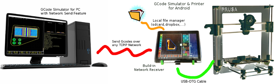
4. Enter G29 S2 to save the value and jump to a new point
5. Repeat steps 3 and 4 until the creation procedure is complete.
6. Enter M500 to write the resulting mesh to EEPROM.
Creating Mesh Bed Leveling using the printer menu (the function must be active in the firmware):
1. Select Prepare and then Auto home (aka G28 command). nine0006
2. Select Prepare and then Level Bed.
3. Wait for on-screen instructions to begin. Press the "twist" on the screen when the inscription "Click to Begin" appears. The head will go to the first grid point.
4. Use the thumbwheel to raise or lower the nozzle to align the nozzle with the paper. Same as when leveling the table. After you have achieved the desired gap between the nozzle and the piece of paper, press the "twist". The head will move to a new grid point.
5. Repeat step 4 until the program has passed all points. nine0006
6. When finished, enter the Control menu and select the Store memory item to save the created mesh to EEPROM.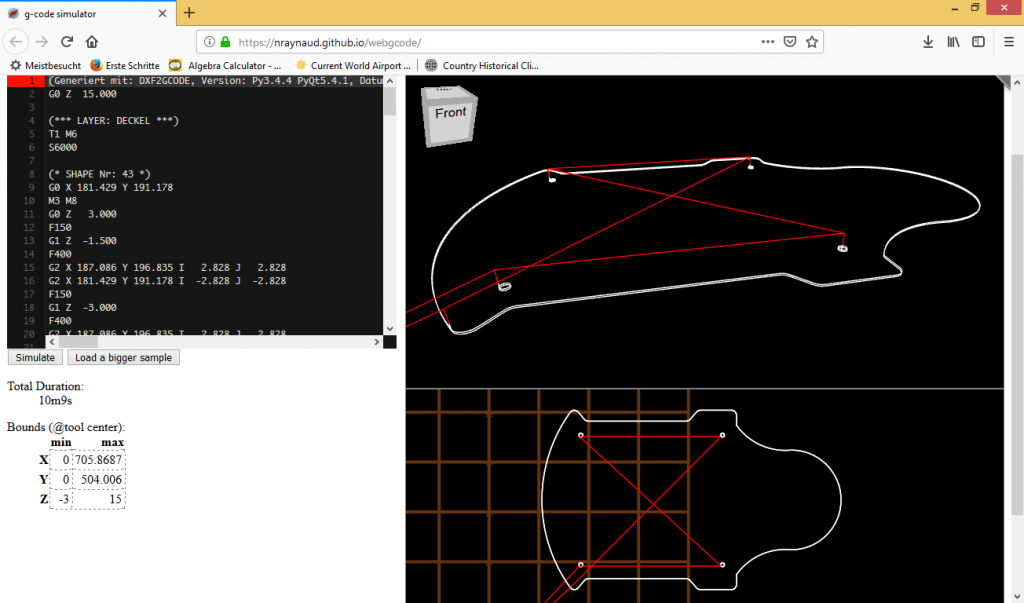
To use the grid stored in EEPROM when printing, use the command
M420 S1 (See M420).
G90 - Setting absolute coordinates
All coordinates are absolute relative to the machine origin.
G91 - Set relative coordinates nine0214
All coordinates from now on become relative to the last position. Marlin translates all axes into relative coordinates, including the extruder.
G92 Xnnn Ynnn Znnn Ennn - Set position
This command can be used without any additional parameters.
G92 - reset all axis coordinates to zero.
Xnnn - new X coordinate nine0006
Ynnn - new Y coordinate
Znnn - new Z coordinate
Ennn - new extruder position
Example: G92 X10 E90
M-commands
M17 - Enable/Enable all stepper motors
M18 - Remove current from motors
Motors can be turned by hand.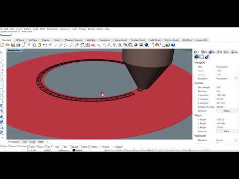 Analog command M84
M20 - List of files on SD card
M21 - SD card initialization
If the SD card is loaded when the printer is turned on, this will happen by default. The SD card must be initialized for other SD card functions to work.
M22 - Release SD card
The specified SD card will be released. On future (random) read attempts, a guaranteed error occurs. Useful before removing the SD card. nine0006
M23 - SD card file selection
Example: M23 filename.gco
M24 - Start/continue printing from SD card
The printer will print from the file selected with the M23 command.
M25 - SD card print pause
M28 - Start writing to SD card
Example: M28 filename.gco.
A file is created on the SD card, designated as filename.gco (if the file exists, it is overwritten) and all subsequent commands to the printer are written to this file.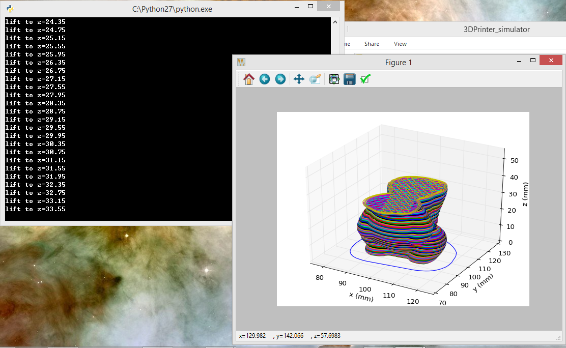 nine0006
M29 - Stop writing to SD card
Example: M29 filename.gco
The file opened by the M28 command is closed and all subsequent commands are executed by the printer in normal mode.
M30 - Delete file from SD card
Example: M30 filename.gco. filename.gco will be deleted.
M32 - Select file and start printing from SD card
Example: M32 filename.gco.
Used for printing from an SD card and works the same as M23 and M24
M80 - Enable ATX Power Supply
Puts the ATX power supply into sleep mode. Does not work on electronics without sleep mode.
M81 - Turn off the ATX power supply
M82 - Set the extruder to absolute mode
M83 - Set extruder to relative mode
allows extruder to be extruder in absolute/relative units
M84 SNNN X, Y, Z, E - transfer motors to the standby mode
SNNN - time per seconds.
If a timeout is specified with Snnn, this command simply sets the stepper motor inactivity timeout.
If motors (X,Y,Z or E) are not specified, this command immediately disables all.
If one or more axes are specified, this command disables the specified ones immediately. For example, "M84 S10" will put stepper motors into standby mode after 10 seconds of inactivity.
M92 Xnnn Ynnn Znnn Ennn - Set the number of steps per axis per unit
Ennn - steps per unit for extruder nine0006
Examples: M92 X87.489 Y87.489 Z87.489 or M92 E420
Allows you to set the number of steps per unit (usually mm) for motors. These values are replaced with the values from the firmware at power up unless written to the EEPROM see M500.
M104 Snnn - Set extruder temperature and DO NOT wait
Snnn - Set temperature
Example: M104 S190
Sets the temperature of the active extruder 190C and immediately returns control (that is, DOES NOT WAIT for the extruder to reach the set temperature).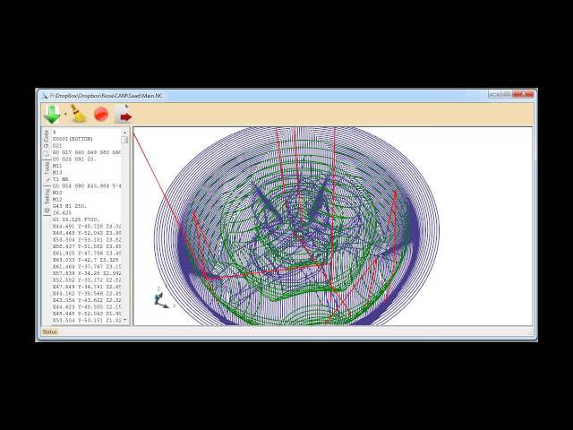 See also M109
M105 - Get Extruder Temperature
Gets the temperature of the active extruder and hot bed in degrees Celsius. The temperature is transmitted to the connected computer. The response sent to the computer might look like this: ok T:201 B:117
M106 Snnn - Turn on the fan blowing part
SNNN - Fan rotation of rotation from 0 to 255 (127 - 50% speed)
m107 - Turn off the fan
m108 - cancel the levy temperature set by M109 and M190, continues printing.
M109 Snnn - Set extruder temperature and wait
Sets the temperature in Celsius and waits for it to be reached. See also M104
M110 Nnnn - Set current line number
Nnnn - Line number
Example: M110 N123
In this example, the number of the current line 123 is set. Thus, it is expected that the next line after this command will be 124.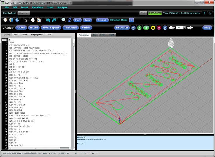
M112 - Emergency Stop
m114 - receipt of current positions 9
m115 - Get a firmware version
m119 - get the status of endings
m140 - establish the temperature of the table - establish the temperature of the table and DO NOT wait
Example: M140 S65
Sets the table temperature to 65C and immediately returns control (ie DOES NOT WAIT for the table to reach the set temperature). See also M190
M190 - Set table temperature and wait
Sets the temperature in Celsius and WAITS to reach it. see M140
M200 Dnnn Tnnn - Set the REAL diameter of the filament rod.
Dnnn – diameter in mm.
Tnnn – extruder number. (can be omitted for single extruder printers)
Example: M200 D1.65
Used to calculate the actual extruded volume. nine0006
See M404 for rating setting.
M201 Xnnn Ynnn Znnn Ennn - Setting of the maximum accelerations (in mm/s in sq.)
for axes.
Ennn - accelerations in mm/s in sq. for the extruder.
Only one/two of the parameters can be used.
Example: M201 X1000 Y1000 Z100 E2000
Use M500 to store parameters in EEPROM
M202 - Setting the maximum acceleration for simple (idle) movement.
!Not used in Marlin! V mm/s in sq. Example: M202 X1000 Y1000
Ennn - max extruder speed. nine0006
Only one/two of the parameters can be used.
Example: M203 X6000 Y6000 Z300 E10000
Use M500 to store parameters in EEPROM.
M204 Pnnn Rnnn Tnnn - Acceleration setting (in mm/sec. in sq.)
Pnnn - Printing acceleration
Rnnn – Retract Acceleration
Tnnn - Accelerations during idle movements
Only one/two of the parameters can be used. nine0006
Example: M204 P800 T3000 R9000
Use M500 to store parameters in EEPROM.
M205 Xnnn, Znnn, Ennn - Setting the maximum jerk (jerk) (mm / s)
Xnnn - jerk along the X and Y axes. (Jerks are the same along these axes)
Znnn - jerk along the Z axis.
Ennn - Jerk for extruder.
Only one/two of the parameters can be used.
Example: M205 X30 Z5 - Set jerk X/Y = 30, Z jerk = 5. nine0006
Use M500 to store parameters in EEPROM.
М206 Xnnn, Ynnn, Znnn - Set offsets relative to limit switches (zero)
Similar to G92 command, but these offsets can be written to EEPROM see M500.
Example: M206 X10.0 Y10.0 Z-0.4
M207 Snnn Fnnn Znnn - Set retract parameters (bar retraction)
Snnn - positive retract value in mm. nine0006
Fnnn – feedrate mm/sec.
Znnn - lift (lift) of the head along the Z axis in mm during retract.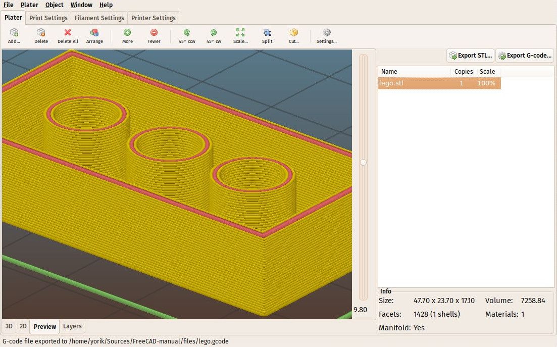 (Helps avoid hitting the model)
Example: M207 S4.0 F2400 Z0.075
Used subsequently for G10 and G11 commands.
Use M500 to store parameters in EEPROM.
M208 Snnn Fnnn – Bar feed recovery parameters after retract
Snnn – positive feed value in mm. nine0006
Fnnn – feedrate mm/sec.
Use M500 to store parameters in EEPROM.
M209 Snnn – On/off automatic retraction
Snnn – value 1 – on, 0 – off
Used if the slicer does not support the G10 and G11 commands.
Each extrusion command will be classified as a retract, depending on the value (positive or negative).
M218 Tnnn Xnnn Ynnn – head offset setting
Tnnn - head number
Xnnn, Ynnn – X,Y coordinates.
Example: M218 T0 X50 Y10.5
M301 Hnnn Pnnn Innn Dnnn — Write hotend PID parameters(!)
Hnnn – extruder number.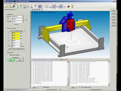 h2 - the first exruder (hotend).
Pnnn - Proportional gain (Kp)
Innn - Integral factor (Ki) nine0006
Dnnn - Derivative coefficient (Kd)
Example: M301 h2 P1 I2 D3
Use M500 to store parameters in EEPROM.
See M304 for writing table PID.
M302 Snnn - Allow extrusion at Snnn and above.
Snnn - Set temperature
Example: M302 S170 - enable extrusion (turn on the extruder motor) at a nozzle temperature of 170C and above. M302 S0 - extrude at any temperature. nine0006
M303 Ennn Snnn Cnnn - Start PID calibration process for table/hotend
Ennn - E0 hotend, E1 table.
Snnn is the calibration temperature.
Cnnn – number of calibration cycles. More cycles - more precise parameters.
Example M303 E1 C8 S110 – table PID calibration at 110C for 8 cycles.
The PID parameters will be displayed as a string on the terminal screen of a program running in connection with the printer, such as Repetier-Host.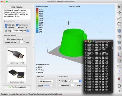 nine0006
M304 Pnnn Innn Dnnn - Write table PID parameters (!)
Pnnn - Coefficient proportional (Kp)
Innn - Integral factor (Ki)
Dnnn - Derivative coefficient (Kd)
Example: M301 h2 P1 I2 D3
M301 - without parameters will display the current parameters.
Use M500 to store parameters in EEPROM.
For writing extruder PID see M301. nine0006
М404 Wnnn - Setting the nominal filament thickness 1.75 or 3.
Wnnn - nominal (theoretical) filament thickness in mm.
Example: M404 W1.75
M404 - without parameters will display the current nominal value as a string.
This value is used to determine the percentage difference in the automatic rate adjustment in response to the measured filament width and must match the value used for the filament width in slicer settings. nine0006
Set actual filament thickness, see M200.
М420 Snnn - Enable/disable the use of the table curvature compensation grid (MESH_BED_LEVELING)
Snnn - S1 on, S0 off.